Apr 28, 2017 - Circulation Control, Vertical Axis Wind Turbine, VAWT, Flow Control, .... the ratio of rotational velocity (Ï) to the free stream velocity (Vâ), shown in Eq- ..... Energy Magazine, 7, 1540-7977. https://doi.org/10.1109/mpe.
Smart Grid and Renewable Energy, 2017, 8, 99-113 http://www.scirp.org/journal/sgre ISSN Online: 2151-4844 ISSN Print: 2151-481X
Dynamic Circulation Control for a Vertical Axis Wind Turbine using Virtual Solidity Matching Jay P. Wilhelm1, Andrew C. Nix2, Chad C. Panther2, Wade W. Huebsch2, James E. Smith2 Mechanical Engineering Department, Russ College of Engineering and Technology, Ohio University, Athens, OH, USA Mechanical and Aerospace Engineering Department, Statler College of Engineering and Mineral Resources, West Virginia University, Morgantown, WV, USA
1 2
How to cite this paper: Wilhelm, J.P., Nix, A.C., Panther, C.C., Huebsch, W.W. and Smith, J.E. (2017) Dynamic Circulation Control for a Vertical Axis Wind Turbine using Virtual Solidity Matching. Smart Grid and Renewable Energy, 8, 99-113. https://doi.org/10.4236/sgre.2017.84007 Received: March 11, 2017 Accepted: April 25, 2017 Published: April 28, 2017 Copyright © 2017 by authors and Scientific Research Publishing Inc. This work is licensed under the Creative Commons Attribution International License (CC BY 4.0). http://creativecommons.org/licenses/by/4.0/ Open Access
Abstract Vertical Axis Wind Turbines (VAWTs) with fixed pitch blades have a limited power capture performance envelope as the Tip Speed Ratio (TSR) changes. Circulation Control (CC) has been proposed and simulated to possibly increase power capture of a VAWT using constant CC jet momentum, but a practical method of minimizing CC usage has yet to be explored. In addition, VAWTs are typically limited in power capture performance either by a maximum peak at a small set of TSR or wide operating TSR at fractions of the peak performance based on the design solidity. Both the reduced jet usage and solidity limitation were addressed by developing a method of dynamically using CC to perform a virtual solidity change. The developed method described within this work used CC to change blade aerodynamics to specifically match a maximum performing static solidity or wake shape at a given TSR. Simulation results using an existing aerodynamics model indicated a significant reduction in the required CC jet momentum compared to a constant CC system along with control over power capture for a CC-VAWT.
Keywords Circulation Control, Vertical Axis Wind Turbine, VAWT, Flow Control, Solidity Matching
1. Introduction Wind turbines can provide an inexpensive localized renewable power source, supplement an existing supply grid, or provide a stand-alone source of power. The installation and usage of wind turbines have grown at a massive rate over the last decade and are primed to become a large producer of power in the US and abroad [1] [2]. As such, it is desired that wind turbines operate efficiently DOI: 10.4236/sgre.2017.84007
April 28, 2017
J. P. Wilhelm et al.
within their deployment environment of varying wind speeds. A major drawback of Vertical Axis Wind Turbines (VAWTs), thus far, is that power capture cannot be reliably controlled to compensate for changing wind speeds [3] [4]. Therefore, much interest has focused on methods of controlling VAWT blade aerodynamics to increase power capture for a range of wind speeds. A thin injection slot of high velocity air that adheres to a rounded trailing edge due to the Coanda effect, known as Circulation Control (CC), is a possible solution to increasing a VAWT’s power capture. Simulations of constant jet momentum CC were investigated and found to increase the turbine’s coefficient of performance [5]. The problem with constant jet momentum usage for a VAWT is that the power required may exceed the power captured. Dynamic usage of CC was explored to increase performance in a similar manner to the effects of constant CC while using dynamic CC jet momentum. This paper applied a previously developed VAWT aerodynamics model [6] to determine CC jet momentum values required to match solidity or the wake shape through a range of rotational angles and tip speed ratios. Dynamic utilization of CC varied with rotation speed, blade control region, CC schedule, to achieve maximum performance at varying TSR. Results are presented to create a map of required CC jet momentum required versus tip speed ratio and angle of rotation.
1.1. Circulation Control Wind turbine blade lift control mechanisms that ultimately control power capture have included pitch variation or feathering, trailing edge flaps, vortex-generators, and even plasma systems [3] [4] [7] [8] [9] [10]. During rotation of a VAWT, each blade experiences different flow conditions requiring individual control for maximum efficiency [11]. Excluding plasma actuation by Greenblatt [12], all of the systems have required some fashion of a moving aerodynamic device or pitching blade to control power generation with varying results and similar conclusions of a complicated and fragile actuation mechanism. Plasma actuation was investigated by Greenblatt [12] and found that its use could increase power capture (~5%) when used on the upwind portion of rotation. Each investigated aerodynamic control method has merit, but ultimately a more reliable and simpler mechanism of controlling blade lift was sought. A possible candidate is the pneumatic trailing edge jet slots that contain the actuation or valving mechanism inside the blade. Jet slots due not require any moving components external to the blade and avoid potential pitching blade failures that currently are limiting VAWT’s such as indicated by Pawsey [3]. The use of pneumatic devices in the form of trailing edge jets have been employed or been under consideration in the field of aerodynamic flow control dating back to the 1930’s. Trailing edge jets are still being experimented with as a method of flow control [13] [14] [15] [16] [17] along with successful application to aircraft such as the C-17. Implementations include sharp trailing edges of otherwise conventional airfoils that are replaced with rounded or bluff surfaces, with circular cross-sections, containing thin tangential jet slots located on the aft 100
J. P. Wilhelm et al.
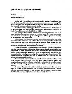
upper surface. Combining the jet with a rounded trailing edge is commonly known as Circulation Control, which has potential to greatly (sometimes a 10x improvement) increase lift generated [13] [16] [18]-[23]. The potential increase in lift and lack of a moving device external to the blade led the authors to focus on development of a method to efficiently use CC to control power capture of a VAWT. CC is characterized by a non-dimensional parameter, known as the jet momentum coefficient, denoted as Cµ [20]. This coefficient is defined as the ratio of the jet’s momentum to the free stream momentum. The jet momentum coefficient can be combined with the airfoil’s lift to show efficiency, which has an upper limit depending upon airfoil geometry according to Abramson [18]. In regards to a VAWT, CC could be considered a fluid based mechanism to control circulation and when examining lift, the virtual camber of a airfoil. CC is capable of both increasing and decreasing lift using upper and lowers lots respectively. Wolfe [24] first investigated the concept of a CC-VAWT in the late 1970’s at West Virginia University (WVU). Their CC-VAWT utilized a mostly hollow blade where jet source air was supplied through structural support arms and controlled at the vertical turbine mast. Initially, the jet momentum was controlled using a hub located value and cam system, which proved troublesome to maintain. Interest was lost as other energy technologies outpaced development of the VAWT, but renewed investigations in the effort picked up at WVU in 2008 due to availability of pneumatic values that could be located within the blade. Recently, the concept of using CC to augment lift for increased energy capture was overviewed by Smith [25] and a blade shape and internal pneumatic design was investigated by Graham and Panther [15] [26]. The combination of CC and a VAWT that contains a valving system with upper and lower trailing edge jets has become known as the CC-VAWT within the current effort. VAWT blade design relies upon symmetric airfoils as the blade will experience both positive and negative angles of attack during the upwind and downwind portions of rotation [27]. The internals of a CC-VAWT blade containing an air supply, pneumatic valve, diffuser, and lower and upper slots housed within a 23% ellipse airfoil was conceptualized, shown in Figure 1, using modern valving
Figure 1. Cross-section of a circulation controlled airfoil. 101
J. P. Wilhelm et al.
components to first prove possibility of construction. The selected airfoil and envisioned internal air delivery system was known to maximize CC effects and satisfy the symmetrical needs of a VAWT [5].
1.2. VAWT Non-Dimensional Parameters Three important non-dimensional parameters must first be discussed regarding VAWTs to gain an understanding of design choices and performance. First, the defining efficiency factor of a wind turbine is the coefficient of performance ( C p ), defined as the non-dimensional wind turbine power coefficient for a full rotation including all blades, shown in Equation (1) [28], where the power of the turbine (Pturbine) is normalized by the air density (ρ), wind velocity (V) and swept area of the airfoils (A). The coefficient of performance is the non-dimensional power of the wind turbine. Second, the solidity (σ) is the non-dimensional size factor of a VAWT, and is shown in Equation (2), where Nb is the number of blades, C is the blade chord and R is the turbine radius. Finally, the TSR or λ is the ratio of rotational velocity (ω) to the free stream velocity (V∞), shown in Equation (3). TSR (λ) is used as a non-dimensional speed parameter that allows designers to evaluate turbine rotational speed to wind speed ratio instead of wind speed alone. The parameters σ and λ are combined with blade aerodynamic characteristics and used within a VAWT aerodynamics model to determine
Cp . Cp =
Pturbine 1 2 ρ AV∞3
(1)
Nb c R
(2)
σ=
λ=
ωR V∞
(3)
1.3. Vortex Method VAWT Modeling An aerodynamic analytical computer simulation model was needed to study power capture for different CC usage configurations of the CC-VAWT. Parameters of interest were the blade angle of attack, and all aerodynamic forces such as lift, drag, normal, and tangential. CFD is a well known and widely used aerodynamic modeling technique, but can be computationally intensive [29] compared to existing and simplified methods of wind turbine modeling. An alternative technique that predates CFD is known as the vortex method and can provide comparable results to experiments in a computationally minimal footprint as demonstrated by previous research [3] [6] [30] [31]. VAWTs are simulated within the vortex method using potential flow models where vortices are shed off the blade during rotation, are moved down wind by the free stream, and influence the blade local velocity that is a combination of the free stream, rotational, and vortex field intensity and direction [6]. The vortex method allows for upwind/downwind blade wake interactions [32] and with proper modifications, aerodynamic blade changes during rotation. Another area that could possibly be 102
J. P. Wilhelm et al.
simulated is dynamic stall [3]. The effects of dynamic stall and CC have been investigated by Yen [14] and indicate that without dynamic stall capture, the model may over predict power capture for low TSR ( λ ≤ 3 ). The specific dynamic stall characteristics were unavailable for the CC blade design chosen (23% ellipse) and therefore dynamic stall was unable to be included in the CC-VAWT aerodynamics model. All simulations run throughout this paper included two blades, rotational step of 7.5˚, convergence criteria, and induced velocity of a vortex core as defined in [5]. The effects of constant jet CC were included into a VAWT vortex model in 2009 by Wilhelm [6]. This work showed the performance of a CC-VAWT could be both increased and decreased when using constant momentum coefficients at all times. Simulation results of the vortex model included comparable trends of past models without CC, providing sufficient validation of a 2D version. The model predicted an improved coefficient of performance for a VAWT (