camera array system as the main acquisition device. We ..... g(pi, Npi ; m(pi), Nm(pi)) = A â Am. (2) .... where cameras i and j observe âvalidâ correspondences.
Dynamic Fluid Surface Acquisition Using a Camera Array Yuanyuan Ding Feng Li Yu Ji Jingyi Yu University of Delaware, Newark, DE 19716 USA {ding,feli,yuji,yu}@cis.udel.edu Abstract Acquiring dynamic 3D fluid surfaces is a challenging problem in computer vision. Single or stereo camera based solutions are sensitive to refraction distortions, fast fluid motions, and calibration errors. In this paper, we present a multi-view based solution for robustly capturing fast evolving fluid wavefronts. We first construct a portable, 3x3 camera array system as the main acquisition device. We elaborately design the system to allow high-resolution and high-speed capture. To recover fluid surfaces, we place a known pattern beneath the surface and position the camera array on top to observe the pattern. By tracking the distorted feature points over time and across cameras, we obtain spatial-temporal correspondence maps and we use them for specular carving to reconstruct the time-varying surface. In case one of the cameras loses track due to distortions or blurs, we use the rest of the cameras to construct the surface and then apply multi-perspective warping to locate the lost-track feature points so that we can continue using the camera in later frames. Our experiments on synthetic and real data demonstrate that our multi-view framework is robust and reliable.
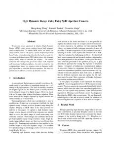
Figure 1. Dynamic Fluid Surface Acquisition. Left shows our camera array for acquiring the surfaces. Right shows the refraction distortion patterns in different cameras.
Recent studies have shown that refraction-based methods methods produce more accurate reconstructions than the reflection-based ones [17]. However, many previous approaches are sensitive to refraction distortions, fast fluid motions, and calibration errors. In this paper, we present a complete multi-view based solution for robustly capturing fast evolving fluid wavefronts. We first construct a portable, 3x3 camera array system as the main acquisition device. Our system is controlled by a single workstation and hence is portable. We also address practical issues such as data streaming and storage and timedivided multiplexing for high speed acquisition. To recover fluid surfaces, we place a known pattern beneath the surface and position the camera array on top to observe the pattern. By tracking the distorted feature points over time and across cameras, we obtain spatial-temporal correspondence maps and we use them for specular carving to reconstruct the time-varying surface. In case one of the cameras loses track due to distortions or blurs, we use the rest cameras to construct the surface and apply multiperspective warping to locate the lost-track feature points so that we can continue using the camera in later frames. We apply our system to capture a variety types of fluid motions. Experiments on synthetic and real data demonstrate that our framework is robust and reliable.
1. Introduction In recent years, modeling dynamic 3D fluid surfaces has attracted much attention from many research fields, ranging from physical-based modeling [11] to oceanography [12]. While tremendous achievements have been made on developing numerical simulators [6] to estimate fluid surface evolutions, the problem of capturing real dynamic 3D fluid surfaces is still challenging: the acquisition system should be non-intrusive, high-speed and high-resolution, and the reconstruction method should be robust in presence or strong distortions and blurs. In computer vision, a commonly adopted solution for fluid surface acquisition is image-based modeling. Single and multi-camera based approaches have sought to take advantage of fluid optical properties and attempted to extract the shape of surfaces from the captured images [18, 1, 17].
2. Related Work Existing image-based solutions for reconstructing real specular surfaces such as mirrors and fluid surfaces can be 1
classified into three categories. Single-Camera Solutions. Solutions in this category use only one camera for recovering the surface. These methods often assume fluid surfaces are piecewise planar and then solve a generalized Structure-from-Motion (SfM) problem [10]. General specular surfaces can also be recovered from distortions [1]. Recent work by Ding et al. [9] first recovers the refraction ray geometry from distorted line patterns (curves) and then approximates surface differential attributes such as curvatures from ray geometry. However, they assume nearly flat surfaces whereas we aim to acquire fast evolving wavefronts. Further, both SfM and shape-from-distortion methods rely on accurately tracking features and are therefore sensitive to image distortions. Our camera array solution resolves this issue via a multiview approach: if one camera loses correspondences, its near cameras can be used to fill in the gap. Stereo-Camera Solutions. One can also use a stereo setup for specular surface reconstruction. Sanderson et al. [19] proposed a stereo camera configuration for resolving ambiguities commonly observed in single-camera based methods. Morris and Kutulakos [17] introduced the notion of refraction disparity and developed new optimization schemes to simultaneously estimate the height field and the normal field. However, similar to the single-camera solutions, these methods still suffer from refraction distortions and motion blurs: once a camera C ∗ loses track of the feature points at a frame, it can no longer track them in its consecutive frames. Our solution resolves this problem by using the rest of the cameras to first approximate the surface and then ray-trace the surface to locate the missing feature points in C ∗ so that we can continue tracking the points. Multi-View Solutions. Finally, one can use multiple cameras for acquiring specular surfaces. Blake [7] measured the variations of specularities from different viewing directions to determine the differential properties of the surface. Bonfort and Sturm [8] used multiple-view geometry to build a volumetric reconstruction of mirror surfaces. Most previous approaches are specifically designed for static specular surfaces. For instance, one can dynamically adjust the calibration pattern to produce reliable correspondences. However, for capturing dynamic fluid surfaces, the pattern needs to be fixed in space and robustly tracking the feature points on the pattern is much more difficult. In addition, the fluid surface is rapidly evolving. Therefore, it is crucial to capture and store the imagery data at high speed to avoid motion blurs.
3. Acquisition Device We first present a portable camera array system for acquiring the fluid surfaces. In recent year, a number of camera systems have been developed for specific imaging tasks. For example, the Stanford light field camera array
Figure 2. (Left) The setup of our fluid surface acquisition system. (Right) We divide the camera array into two groups (gray and black) and interleave the trigger for each group to double the frame rate.
[21, 22, 20, 15] is a two dimensional grid composed of 128 1.3 megapixel firewire cameras which stream live video to a stripped disk array. The MIT light field camera array [23] uses a smaller grid of 64 1.3 megapixel USB webcams for synthesizing dynamic Depth-of-Field effects. These systems require using multiple workstations and their system infrastructure such as the camera grid, interconnects, and workstations are bulky, making them less suitable for onsite tasks. We have constructed a small-scale camera array controlled by a single workstation. Our system uses an array of 9 Pointgrey Flea2 cameras to capture the dynamic fluid surface. We mount the camera array on a metal grid attached to two tripods so that we can easily adjust the height and the orientation of the camera array. The camera array is connected to a single data server via 5 PCI-E Firewire adaptors. The use of Firewire bus allows us to synchronize cameras through the Pointgrey software solution. Data Streaming. Streaming and storing image data from 9 cameras to a single workstation is another challenge. In our system, a camera captures at 8-bit images of resolution 1024x768 at 30fps. This indicates that we need to stream about 2Gbps data. To store the data, previous solutions either use complex computer farm with fast ethernet connections or apply compression on the raw imagery data to reduce the amount of data. For fluid surface acquisition, the use of compression scheme is highly undesirable as it may destroy features in the images. We therefore stream and store uncompressed imagery data. To do so, we use an external SATA disk array as the data storage device. The disk array is equipped with 6 Seagate 1TB SATA disks, and connected to the server through a PCI-E x4 card. We configure RAID 0 for disk array to achieve the maximum performance. It is also worth noting that our system is also more affordable: by eliminating multiple workstations, network devices and external camera synchronization units, our system (including 9 cameras) has a total cost under $10,000. Time-Divided Multiplexing. Since the Flea2 cameras can only achieve a maximum frame rate of 30fps, we have adopted a time divided multiplexing scheme to further improve the frame rate of our system. Our solution is similar to the Stanford light field high speed imaging scheme [22]
Frame #20
Frame #24
Direct LK Tracker
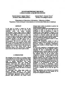
Figure 3. A diagram showing the pipeline of our camera-array based fluid surface reconstruction algorithm.
that interleaves the exposure time at each camera. Specifically, we divide the camera array into two groups, four in one group and five in the other. We set the exposure time of each camera to be 10ms to reduce motion blurs. While all cameras still capture at 30fps, we trigger the second camera group with a 1/60 second delay from the first one. We also develop special algorithms for warping the reconstruction result from the first group to the second (Section 4.2) so that our system is able to perform at 60fps. Experiment Setup. We use a off-the-shelf glass water tank of dimension 30in × 12in × 12in placed firmly on a metal grid to contain dynamic fluids. We print a black-white checkerboard pattern on regular paper, laminate it, and then glue it to a planar plastic plate. We stick this plate onto bottom of the container and use it for both camera calibration and feature tracking. Lens Specs. In our experiments, the choice of camera lenses is also crucial in our acquisition process. For example, a camera’s field-of-view should be large enough to cover the complete fluid surface. In our setup, we choose Rainbow 4.8mm wide angle lens with a focal distance of 12in. Since all cameras are mounted on a reconfigurable rig, we can easily adjust the camera baseline to achieve optimal reconstructions. Calibration. A number of options [15, 23] are available for calibrating the cameras in the array. Since the observable regions of our cameras have large overlaps, we directly use Zhang’s algorithm [25] for calibration by reusing the checkerboard pattern mounted at the bottom of the tank. This approach also has the advantage of automatically calibrating all cameras under the same coordinate system and simplifies our feature warping scheme.
4. Fluid Surface Reconstruction To recover dynamic fluid surfaces using our system, we place a known pattern beneath the surface so that each individual camera in the array will observe a distinct timevarying distortion pattern. We develop a feature tracking algorithm for robustly tracking checkerboard corners under both distortions and motion blurs. In particular, if a camera
Direct LK Tracker
Locally Constrained LK Tracker
Locally Constrained LK Tracker
Frame #28
Direct LK Tracker
Locally Constrained LK Tracker
Figure 4. Classical Lucas-Kanade (L-K) tracker loses track at regions with strong distortions. Our locally constrained L-K tracker is able to robustly track in these regions.
C ∗ in the array loses track, we use the rest cameras to reconstruct the surface and then apply multi-perspective ray tracing to locate the feature points in C ∗ so that we can still use the camera in later frames. We call this process feature warping. The tracking results provide pixel-point correspondences in each camera. We then generate a dense (per-pixel-based) correspondence map and apply specular carving to reconstruct the normal field of the fluid surface. We then integrate the normal field to obtain the actual fluid surface. We further apply feature warping to processing time-divided multiplexing image array data to double the frame rate of our acquisition. Figure 3 illustrates the processing pipeline of our framework.
4.1. Correspondence Maps A crucial step in our fluid surface reconstruction algorithm is to establish feature correspondences. Notice, although each single corner may be strongly distorted and shifted, the local checkerboard structure (e.g., the relative position of neighboring corners) generally remains stable. We therefore introduce the local affine constraints on the square grid. We assume one-to-one correspondence mapping and each feature point (square corner) can be expressed as affine combinations of its neighboring feature points, and the affine coefficients need to be within a certain range. Let I0 and I1 be the two consecutive frames in a camera in the array, (V, E) represents the lattice graph of the square grid where V denotes the checker-board corners and E denotes the edges connecting the corners. Assume that pi = [xi , yi ]T ∈ V denotes the detected or previously tracked corners in I0 and m(pi ) are their correspondences in I1 . Our goal is to establish correspondences between pi and m(pi ). We compute the matching cost as the combination of the geometric error and the appearance error: |V | �
{�I0 (Npi ) − W (I(Npi ))�+
i=1
� λ · g(pi , Npi ; m(pi ), Nm(pi ) )
(1)
L1 L2
Figure 5. Our refraction carving framework. (a) Given the incident and the refracted directions, we can solve for the surface normal. (b) Each voxel will give a different normal estimate. (c) Using an array of cameras, we can find the optimal voxel/normal. (d) Finally, we apply space carving using the normal consistency criteria.
where W is an affine warping function defined by the neighboring corner correspondences. �I0 (Npi ) − W (I(Npi ))� is the appearance matching cost for the local patch around pi . λ is a constant controlling the relative weight between the appearance cost and the geometric costs. g(·) is the geometric cost that measures the geometric dissimilarity between the original checker-board corner set Npi and the candidate corner set Nm(pi ). Assume pi as the affine combination of Npi : pi = A · Npi . A is the affine coefficients, and similarly, Am represent the affine coefficients for m(pi ). We define the geometric cost as: g(pi , Npi ; m(pi ), Nm(pi ) ) = �A − Am �
(2)
We incorporate the matching cost in Eqn. (1) and (2)into the inverse-compositional framework of the Lucas-Kanade (L-K) tracker [4, 3, 5] and use the modified L-K tracker for tracking checker-board corners under refraction distortions. Figure 4 compares the tracking results on one viewing camera using the classical L-K tracker and our approach. Our method is able to robustly track the feature points in presence of strong refraction distortions whereas L-K loses track at these places. Recall that the tracked feature correspondences are rather sparse. Since our goal is to conduct dense multi-view reconstruction, we further construct dense correspondence maps. Given a correspondence map in each camera at every frame, we first compute a distance map using Chamfer Distance Transform, then generate a local Delaunay triangulation using the 8-neighbors for every sample, and finally interpolate per-pixel correspondence (in terms of the horizontal and vertical shifts) using the triangulation. It is important to note that our tracking algorithm may still fail in presence of strong distortions. While this is fatal to most previous single-camera or stereo-camera based approaches [17, 1], our multi-view approach naturally resolves this problem. Specifically, we benefit from the analysis that distortions on specular surfaces are non-generic [13]. Therefore, if one camera C ∗ in the array loses track on a surface patch due to strong distortions, it is unlikely that
the rest cameras will observe the same level of distortions. This indicates that can use the rest cameras to construct the patch. Further, we can apply multi-perspective ray-tracing to locate the lost-track feature points in C ∗ so that we can continue using C ∗ in later frames instead of completely discarding C ∗ .
4.2. Volumetric Reconstruction In the previous subsection, we discussed how to track feature points over time in each viewing camera. At the beginning of the acquisition, we further use the camera array to capture a nearly flat (undisturbed) fluid surface. This process allows us to establish spatial correspondence across the views. Combined with the temporal tracking results, we hence establish spatial-temporal correspondences. Therefore, we can apply specular surface carving [8] for reconstructing the surface. Specifically, given features correspondences between N views, our goal is to produce a volumetric reconstruction of the fluid surface. To do so, we first discretize the bounding volume of the fluid surface into 3D voxels and then measure the consistency of light paths for each voxel. Refraction Light Path Consistency. Assume m is the refractive index of the surface. The incident ray �i, the exit ray �r, and the normal �n should be coplanar, and the incident angle φ1 and exit angle φ2 satisfy Snell’s Law, as shown in Figure 5(a), i.e., sin φ1 =m (3) sin φ2 For every voxel inside the volume, we first project it to each of the observing cameras to get its corresponding pixel coordinate. We then look up the correspondence maps to find its corresponding 3D feature points. As a result, every voxel defines a set of light paths from each of the viewing cameras to the pattern plane. Further, we can solve for the unique normal given by each light path as follows. ˙ x , oy , oz ], the observing camAssume the voxel is at O[o x y z ˙ , q , q ] and the checker board corner poera’s COP is Q[q sition P˙ [px , py , pz ], the normalized incident ray direction �i
and refraction ray direction �r hence are: ˙ ˙ ˙ ˙ �i = O − Q , �r = P − O ˙ ˙ �O˙ − Q� �P˙ − O� Let α denote the angle between �r and �i, we have: φ2 + α = φ1 , cos α = �i · �r Combining it with Eqn. (3), we have: sin(α + φ2 ) sin α m= ⇒ tan φ2 = sin φ2 m − cos α
C*
(4) Image Warped from the Virtual Checkerboard
(5)
(6)
We thus can decompose �i to r�i along �r and its orthogonal direction �h, and compute the orthogonal component as: �h = �i − �r cos α (7) Finally, we can compute the normal direction as: �h ) �n = −(�r + �r⊥ ) = −(�r − tan φ2 ��h� � 1 − (�i · �r)2 = [�i − (�i · �r)�r] − �r m − �i · �r
(8)
Once we obtain the normal estimates for each light path, we can then measure the consistency as: � 1 D= �n�i − n�j � (9) W 1≤i,j≤N,i�=j
where cameras i and j observe ”valid” correspondences at the pixel (we exclude the cameras that lose track due to distortions) and W is the total number of light path pairs. Restricted Search. To reduce the computational cost and improve the robustness, we can use a coarse-to-fine scheme. Conceptually, we can first discretize the volume using large voxels (lower resolution) to obtain an initial estimation of the surface. Based on the rough estimation, we can then refine the voxels to improve the resolution of the reconstruction. Although faster, this simple scheme is also more sensitive to noise and hence less robust. Our solution is to effectively use temporal coherence of the surface. Assume we have finished reconstructing the fluid surface as a height field zk (x, y) for frame k, where x and y correspond to the two discretization dimensions. For every [x, y], we define a search range in z as: [zk (x, y) + L1 mk (x, y) − L2 , z(x, y) + L1 mk (x, y) + L2 ] where mk (x, y) represents the motion vector in z direction of voxel [x, y, zk (x, y)] in frame k, and L1 and L2 are two constants to tolerate the motion estimation errors, as shown in Figure 5(d). This significantly reduces the search range and improve the robustness of the carving scheme. Surface Integration. Our specular carving algorithm outputs both the height map and the normal map of the surface. However, the height map is often much more noisy than the normal map, as shown in Figure 7. We therefore
Checker Board
P Captured Image
Figure 6. In case a camera C ∗ loses track of a feature point P , we use the recovered surface from the rest of the cameras and backtrace P to C ∗ .
choose to use the normal map and integrate it to recover the surface. Surface integration from a gradient field has been well studied and can be formulated as to solve the Poisson equation. In our implementation, we adopt a similar approach to [2] for recovering the surface. To reduce noise, we further smooth the height map to obtain more reliable boundary conditions. Figure 7 compares our reconstruction result with the ground truth on synthetic fluid surfaces. CUDA Implementation. Our volumetric reconstruction algorithm needs to be applied to a large number of high-resolution frames. Since the operation conducted at each voxel is nearly the same (estimating the normal and measuring the consistency), we have implemented a GPU version of the algorithm using NVidia’s CUDA. Compared with the un-optimized CPU solution, our GPU implementation achieves over 100 times speedup on an Nvidia GeForce 9600 Graphics Card. We also use CUDA to implement the surface integration algorithm to form a unified processing pipeline. Feature Warping. Compared with the single or stereo camera based solutions, our multi-view approach can use the rest cameras to recover the surface even if one camera loses track due to distortions or blurs. Further, our implementation interleaves the exposure of two camera groups in order to double the frame rate in our acquisition. In both case, it is essential to ”recover” the lost-track feature points in a single or a group of cameras in order to continue the tracking tasks in later frames. Specifically, given the reconstructed surface as a triangular mesh, our goal is to find where the feature points (corners on the checkerboard) will be located in a viewing camera C ∗ , where C ∗ can be the one that loses track or in a different camera group. Since refraction is non-linear phenomenon, this is a classical inverse ray tracing problem and generally does not have a closed-form solution. Our solution is to apply multi-perspective warping using the recently proposed General Linear Cameras [24]. We first apply forward tracing: for each triangle P˙ 1,2,3 on the mesh, we forward trace the three rays at the vertices from the camera to
(a) Ground Truth Surface
(b) Ground ruth Normal X-Component
(d) Surface by Volumetric Reconstruction (e) Recovered Normal X-Component
(g) Recovered Surface by Integration
(h) Rendered Using Groundtruth Surface
(c) Ground ruth Normal Y-Component
(f) Recovered Normal Y-Component
Tracking Frame #100 @ View #7
Tracking Frame #100 @ View #1
Recovered High Map
Recovered Surface
(i) Rendered Using Recovered Surface
Figure 8. Results on real data. Top row shows the feature tracking results on two views. Bottom row shows the recovered height field. Figure 7. Results on synthetic data. (a-c) show the ground truth height field and normal field. (d-f) show the corresponding raw refraction carving results. Notice that the recovered height field is very noisy but the normal field is highly accurate. (g) We integrate (e-f) using the boundary from (d) to obtain the final reconstruction. (h-i) we compare the ray traced refraction distortions on the ground truth surface (h) and our reconstruction (i).
checkerboard as �r1,2,3 , which also defines a local GLC. We 0 intersect the rays with the checker-board plane at P˙1,2,3 . We 0 ˙0 ˙0 ˙ then find checkerboard corners inside ΔP1 P2 P3 and using the local GLC to compute its refraction ray r� and trace the ray back to C ∗ and find its corresponding pixel coordinate.
5. Results and Discussions We have validated our framework on both synthetic and real fluid surfaces. For synthetic surfaces, we use the PovRay Ray Tracer to render 9 image sequences of fluid surfaces from a virtual 3x3 camera array. For real surfaces, we capture an array of video streams of the surface using our acquisition device. Synthetic Surfaces. We first conduct experiments using our method on simulated fluid motions. In Figure 9 column 2, we show sample frames of a ”drop” wave sequence, where the initial wavefront is a Gaussian function 2 2 z(x, y) = 0.1e−(x−w/2) −(y−h/2) , where w = h = 128. We assume that the fluid dynamics follows the NavierStokes (NS) equation and propagate the wave via a discrete NS solver [16]. We use a checkerboard with 23x35 grids of unit squares and position it at z = 0. We further set the refraction index of the fluid as 1.33 to emulate water. Using the PovRay, we render images from a 3x3 camera array positioned at z = 30. The camera plane is se to be parallel to the xy plane and the FOV of each camera set to match the real ones in our camera array. We start with detecting all feature points (corners) at the first frame and correlate them with the ones on the checker-
board. As the wavefront propagates, we apply our modified L-K algorithm to track these features over time. Since all frames are rendered without motion blurs or noise, we found our algorithm highly robust for establishing spatialtemporal correspondence maps. Next, we combine the tracking results with the ground truth camera parameters for volumetric reconstruction. We apply our specular carving scheme at a resolution of 100x100 in xy dimension. The volumetric reconstruction provides a height map and a normal map at each time instance. We observe that, by using the normal consistency constraint, the recovered normal maps are much more accurate than the height map, as shown in Figure 7. Finally, we integrate the normal map, where the boundary of the surface is extracted from the recovered height field. The bottom row of Figure 7(g) shows the recovered fluid surface at a specific frame. To illustrate the robustness of our approach over time, we show the reconstruction results at different time frames in Fig 9. Compared with the ground truth, our method faithfully captures shape deformations of the fluid surface over time. The complete recovered sequences can be found in the supplementary materials. We have further computed the actual reconstruction errors. Specifically, we sample the surface at a 100x100 resolution and compute the error in the height at each grid. The average error is 1.47 × 10⁻⁴ for the Gaussian wave sequence and less than 2.63 × 10⁻⁴ for the other sequences. Real Surfaces. To capture real fluid surfaces, we set up the camera array system as shown in Figure 2(Left). We align the cameras so that they lie approximately on the same plane parallel to the checkerboard plane. We first calibrate the cameras in the array using Zhang’s algorithm [25] with a duplicated checkerboard. We then take an image of the undisturbed water surface and detect feature correspondences for the 0th frame. Notice that the translation of the pattern due to refractions provide an initial height of the surface which we will use in our specular carving algorithm.
Images of View #1 Frame #20
Frame #99
Ground-truth
Recovered Surface
Frame #20
Frame #20
Frame #99
Frame #99
Reconstruction Error Map Frame #20
Frame #99
Figure 9. Results on a synthetic ”drop” wave. The complete sequences (ground truth and our reconstruction) can be found in the supplementary video.
We separate 9 cameras into two groups, as shown in Figure 2(Right). The capture time is interleaved by 16.67ms. To generate fluid motions without disturbing the camera setup, we use a hair dryer to blow air onto the surface. We start with reconstructing the first frame using cameras in group A. Similar to the synthetic case, we detect feature correspondences and apply specular carving to recover the normal field and then the height field. Figure 8 shows the tracked features from two views and reconstructed surface. Given the recovered surface, we apply multi-perspective ray tracing to locate the feature points in cameras in group B. We then reapply the tracking algorithm on images captured by group B, with the warped feature points as their previous frames. Using the correspondence results, we recover the surface at the second frame. We repeat this process by iteratively warping the reconstructed surface between group A and B to improve the robustness in tracking. When parts of a camera’s frame lose track due to distortions or blurs, we simply discard the corresponding portion and use the rest of the cameras for reconstruction. We then apply multi-perspective ray tracing to locate the actual feature points in the camera so that we can continue to use the camera in its later frames. Figure 10 shows four acquired frames in the central camera in the array and their corresponding reconstruction results. Notice that several patches on the surface exhibit severe distortions or blurs, our algorithm is still able to reconstruct reasonable surfaces and continue tracking the missing feature points using the warped results. We refer the reviewers to the supplementary videos for completely reconstructed sequences.
6. Conclusion and Future Work We have presented a new framework for reconstructing dynamic fluid surfaces by using a camera array. It is the first multi-view (≥ 3) solution for fluid surface acquisition. We have addressed many practical issues, ranging from hardware designs, to data streaming and storage, and
to robust reconstruction. We have validated our approach on both synthetic and real world specular surfaces. Experiments have demonstrated that our framework is robust and accurate. In particular, our solution can handle the challenging problem of losing track of feature points which can be detrimental or even fatal to single-camera or stereo based methods. Further, by using time-divided multiplexing, our method is capable of capturing fast evolving fluid wavefronts. An important future direction is to integrate the fluid dynamics model with the acquired fluid surfaces. Like most previous approaches, our framework focuses on reconstructing individual frames without considering temporal coherence. On one hand, we plan to explore how to find the optimal surface that obeys the fluid dynamics and has the minimal distance to our initial reconstruction. On the other, we will investigate how to use the recovered dynamic fluid surfaces to infer or validate existing fluid dynamics models. Finally, we plan to apply our system for acquiring wavefront of more complex geometry such as folding or breaking waves. The challenge there is that the refraction path consistency measure becomes obsolete. Since our cameraarray simultaneously capture the scene from multiple viewpoints, a potential solution is to use light-path triangulation [14]. However, previous solutions rely on varying the lighting/viewing directions for capturing static objects and hence are not directly applicable to acquiring fast evolving fluid surfaces. In the future, we will investigate combining our camera-array with coded illuminations or with a projector array for conducting light-path triangulation at every frame. Acknowledgement This project was partially supported by the National Science Foundation under grants MSPA-MCS-0625931 and IIS-RI1016395, and by the Air Force Office of Scientific Research under the YIP Award.
Frame #44
Frame #55
Frame #60
Frame #79
Frame #44
Frame #55
Frame #60
Frame #79
Frame #44
Frame #55
Frame #60
Frame #79
Figure 10. Results on real data. From top to bottom: the captured frames from the central camera, the recovered normal field, and the recovered height field. The complete sequence can be found in the supplementary video.
References [1] S. Agarwal, S. P. Mallick, D. Kriegman, and S. Belongie. On refractive optical flow. In ECCV 04. 1, 2, 4 [2] A. Agrawal and R. Raskar. What is the range of surface reconstructions from a gradient field? In ECCV ’06. 5 [3] S. Baker, R. Gross, T. Ishikawa, and I. Matthews. Lucas-kanade 20 years on: A unifying framework: Part 2. IJCV, 2003. 4 [4] S. Baker, R. Gross, and I. Matthews. Lucas-kanade 20 years on: A unifying framework: Part 3. IJCV, 2002. 4 [5] S. Baker and I. Matthews. Lucas-kanade 20 years on: A unifying framework. IJCV, 2004. 4 [6] W. J. D. Bateman, C. Swan, and P. H. Taylor. On the efficient numerical simulation of directionally spread surface water waves. J. Comput. Phys., 174:277–305, November 2001. 1 [7] A. Blake. Specular stereo. In Proc. of the Ninth International Joint Conference on Artificial Intelligence, pages 973–976, 1985. 2 [8] T. Bonfort and P. Sturm. Voxel carving for specular surfaces. In ICCV ’03. 2, 4 [9] Y. Ding, J. Yu, and P. F. Sturm. Recovering specular surfaces using curved line images. In CVPR ’09. 2 [10] P. Flach and H.-G. Maas. Vision-based techniques for refraction analysis in applications of terrestial geodesy. Int. Archives of Photogrammetry and Remote Sensing, pages 195–201, 2000. 2 [11] N. Foster and R. Fedkiw. Practical animation of liquids. In SIGGRAPH ’01: Proceedings of the 28th annual conference on Computer graphics and interactive techniques, pages 23–30, New York, NY, USA, 2001. ACM. 1 [12] B. J¨ahne, J. Klinke, and S. Waas. Imaging of short ocean wind waves: a critical theoretical review. Journal of the Optical Society of America A, 11:2197–2209, Aug. 1994. 1
[13] J. J. Koenderink. Solid shape. MIT Press, 1990. 4 [14] K. N. Kutulakos and E. Steger. A theory of refractive and specular 3d shape by light-path triangulation. In ICCV ’05. 7 [15] M. Levoy, B. Chen, V. Vaish, M. Horowitz, I. McDowall, and M. Bolas. Synthetic aperture confocal imaging. TOG, 2004. 2, 3 [16] F. Li, L. Xu, P. Guyenne, and J. Yu. Recovering fluid-type motions using navier-stokes potential flow. CVPR, 2010. 6 [17] N. J. W. Morris and K. N. Kutulakos. Dynamic refraction stereo. In ICCV ’05, pages 1573–1580. 1, 2, 4 [18] H. Murase. Radiometry. chapter Surface shape reconstruction of an undulating transparent object, pages 213–217. Jones and Bartlett Publishers, Inc., , USA, 1992. 1 [19] A. C. Sanderson, L. E. Weiss, and S. K. Nayar. Structured highlight inspection of specular surfaces. TPAMI, 1988. 2 [20] V. Vaish, M. Levoy, R. Szeliski, C. L. Zitnick, and S. B. Kang. Reconstructing occluded surfaces using synthetic apertures: Stereo, focus and robust measures. In CVPR, 2006. 2 [21] B. Wilburn, N. Joshi, V. Vaish, M. Levoy, and M. Horowitz. Highspeed videography using a dense camera array. In In IEEE Society Conference on Pattern Recognition CVPR, pages 294–301, 2004. 2 [22] B. Wilburn, N. Joshi, V. Vaish, E.-V. Talvala, E. Antunez, A. Barth, A. Adams, M. Horowitz, and M. Levoy. High performance imaging using large camera arrays. TOC, 2005. 2 [23] J. C. Yang, M. Everett, C. Buehler, and L. McMillan. A real-time distributed light field camera. In EGSR, 2002. 2, 3 [24] J. Yu and L. McMillan. General linear cameras. In ECCV, 2004. 5 [25] Z. Zhang. A flexible new technique for camera calibration. TPAMI, 22:1330–1334, 2000. 3, 6