In this paper we propose a codec adaptation algorithm, based on a ... the G.711 voice codec for two types of VoIP calls, the fast and the slow ones, which use a ...
Dynamic measurement-based codec selection for VoIP in multirate IEEE 802.11 WLANs Anna Sfairopoulou, Carlos Maci´an, Boris Bellalta Universitat Pompeu Fabra P. Circumval.laci´o, 8, 08003 Barcelona, Spain Tel: +34 93 542 18 95 Email: {anna.sfairopoulou, carlos.macian, boris.bellalta}@upf.edu
TD(07)018 The 8th COST 290 Management Committee Meeting Universidad de M´alaga, Spain, February 15-17, 2007 Abstract In wireless multirate environment users can suffer rate changes due to various factors while maintaining active voice over IP (VoIP) sessions with other users connected to the wired network. This creates a very hostile environment for VoIP, provoking serious quality of service degradation in all active sessions. Building upon our previous results, we propose a centralized version of our codec adaptation algorithm, which allows a cell-wide optimization of network resources and voice quality, based on the combined feedback from Real-Time Control Protocol (RTCP) packets and the MAC layer. A comparison of both the centralized and distributed versions of the algorithm is provided for a wired-wireless scenario, showing an important capacity and quality increase over the standard case. Keywords: RTP/RTCP, QoS, VoIP, multi-rate 802.11
COST 290: Traffic and QoS Management in Wireless Multimedia Networks http://www.cost290.org
1
1
Introduction
Voice over IP (VoIP) over wireless LANs (WLANs) has been a hot research topic during the past years due to the widespread adoption and ease-of-use of both technologies. The popularity of such combination increases since it appears to be a cheap alternative to traditional fixed telephony or even to cellular telephony. Nevertheless, there are still problems when it comes to implementing such a solution. The capacity of a wireless cell in terms of number of supported calls, as well as the QoS of voice over wireless under different channel conditions, are crucial for deciding whether this technology can be widely deployed and accepted. In spite of all the research efforts on this area, there are still unsolved issues concerning the quality of VoIP calls, most commonly caused by the specific wireless network characteristics listed below: • Unfairness between uplink and downlink streams [8] • High protocol layer overheads • Fast VoIP degradation in presence of TCP flows [1] • Variable capacity due to multi-rate transmissions [3] Although the first three problems have been already analyzed in previous works, there is a need for further research considering the last problem. In multi-rate IEEE 802.11-based wireless LAN (WLAN), sporadic rate changes can occur in a mobile node (MN) caused by various factors, such as distance increase between the two wireless end-points, presence of walls when entering a room, atmospheric meteorites (e.g., rain), etc. In this case, a rate change on one transmitter not only affects its corresponding call, but it also dramatically impacts all the other active calls, as explained in detail in chapter 2. As a consequence, it produces a general degradation of the system performance, with active calls being dropped and reducing the free space for new ones, which results in a higher blocking probability, provoking an overall suboptimal allocation of the network resources. In this paper we propose a codec adaptation algorithm, based on a combination of feedback from RealTime Control Protocol (RTCP) packets and the MAC layer, to help solve this problem. The feedback consists of the information that can be obtained from the periodic RTCP packets, like packet loss rate, end-to-end delay and jitter, as well as the announcements of rate changes arriving from the MAC layer. These parameters are constantly monitored in real-time and can trigger a recovery mechanism to adapt the call characteristics, and most importantly the codec that is being used, to the new channel conditions. Since the use of RTCP is very common in VoIP transmission as a complement to Real-Time Transport Protocol (RTP), the algorithm provides a quite simple solution, easy to implement and to install. The rest of the paper is organized as follows: In chapter 2 we briefly describe the problematic of a multirate environment on VoIP sessions. In chapter 3 we have a look at previous work on similar problems and 2
T(11 Mbps) T(11 Mbps)
(a)
T(11 Mbps)
T(1 Mbps)
(b) Observation time
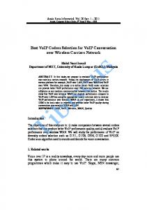
Figure 1: Transmission when (a) both nodes use R rate and (b) when one node changes to rate R’
the proposed solutions until now, while in chapter 4 we analyze our solution and the Codec Adaptation Algorithm in more detail and in chapter 5 we consider two possible implementations of it, centralized and distributed. Finally, in chapter 6 we present the simulation results and chapter 7 concludes the paper.
2
Problem Statement - A Multi-rate-based MAC
Multi-rate transmission is one of the key features of the IEEE 802.11 [4] PHY/MAC specifications which allow each mobile node to select its physical layer parameters (modulation and channel coding) to optimize the bit transmission over the noise/fading-prone channel. However, when a MN reduces its rate, the saturation point for the shared channel is reduced, affecting all active calls independently of whether they observe good or bad channel conditions [3]. To give a simplified example, let us suppose that we have two nodes, both transmitting at a rate R. If we assume that both nodes use the same packet size L then the time each of the nodes will occupy the shared channel will be T = L/R. If now one of the nodes starts transmitting at a lower rate R0 then the time that this will occupy the channel changes to T 0 = L/R0 , where T < T 0 . Occupying the shared medium for a longer period of time means less available transmission time for the fast node resulting to less number of total packets transmitted during the same period of time, even though the fast node does not perceive any change in its channel conditions. Figure 1 presents this example; in the first case (a) both nodes transmit an equal number of 3 packets each, while in case (b) when one node starts trasmitting at a lower rate the number of transmitted packets change to 2 for both the fast and the slow node. This effect lowers the total saturation point of the cell, causing high packet losses due to buffer overflows and thus severe problems on the quality of VoIP transmission, with the effect being more evident on the fast nodes. In Figure 2 the feasible distribution of simultaneous VoIP calls in a cell is plotted: considering the use of the G.711 voice codec for two types of VoIP calls, the fast and the slow ones, which use a data rate of 11 Mbps and 1 Mbps respectively, the maximum number of active calls drops as fast calls change to slow calls. For example, with 9 VoIP calls active (the maximum number of simultaneously active calls at 11 Mbps), if just 1 call changes to the lower rate, the new state becomes not feasible, provoking that all active calls
3
perceive a QoS degradation, as they can not obtain their required bandwidth. Figure 2 has been obtained using the DCF (Distributed Coordination Function) analytical model presented in [1] and adapted for the multi-rate case considering that the same rate is used for the communication between the MN and the AP (Access Point) and also from the AP to the MN. The AP’s effective rate, as all flows have the same offered traffic load, is computed from the average of them. Furthermore, notice that the throughput refers to the MAC layer, so it contains the RTP, UDP and IP headers, which results in a bandwidth for each call equal to 80 Kbps when using G.711 codec.
Figure 2: Bandwidth obtained by the active calls in the presence of fast and slow calls The most common solution so far has been to block the call that suffered the rate change, in order for the others to keep working properly. What we propose is a change of codec for both the slow call and/or some of the fast ones, that will help the system adapt to the new conditions without any call drop and without severe QoS degradation.
3
Related Work
There has been few previous work focusing on RTCP feedback to adjust the quality of the transmitted media. The most similar proposal to our work is the one presented in [10], where the authors propose a voice quality monitoring mechanism based on data gathered from RTCP. Their work puts forward an algorithm and claims to be a simple solution, but without entering in details about the algorithm. It does not use as a working environment a multi-rate wireless, which in our case is the main cause of the problem, and therefore does not take advantage of any lower layer information. In [11] their research area is a distributed admission control mechanisms with an evaluation of the system’s actual load using ICMP echo messages (pings) in order to determine whether or not to admit new calls.
4
There is no concern for calls already in progress, while in our work we support real-time codec adjustment for ongoing calls. Furthermore, RTCP provides more elaborate information on the call quality than does ICMP, simplifying the evaluation process. The work presented in [20] proposes the use of RTT to calculate the delay of the channel and estimate its congestion state. They focus on the problem presented in a wired/wireless scenario where the Access Point acts as a bottleneck creating congestion and thus delay and losses unacceptable for VoIP. The solution proposed is based on a Vegas-like rate control algorithm, which determines the current congestion of the system and on a VoIP border gateway between the wired and wireless network, which performs transcoding according to the current rate obtained from the rate control. Although an interesting solution, the transcoding process is quite heavy requiring a lot of processing capacity while our solution consists of a light algorithm in terms of processing effort. Furthermore, there is no cross-layer transaction and no possibility for a distributed implementation since it depends on a central element, the VoIP gateway. The work in [19] also presents similarities to ours. The authors propose a centralized mechanism to control the access of new users depending on the congestion level of the network and the percentage of channel utilization, as well as a mechanism to adjust the codecs for video and voice sessions so as to solve the congestion. Their method, apart from being completely centralized with the need of a AP-RMS server, is much more drastic than ours, since the solution proposed is to reduce the codec to a lower quality one for all calls when congestion is detected, while in our algorithm only some of the calls will have to suffer a codec change. Additionally, the transmission channel parameters are the same for all users in the scenario they use, while we focus mainly on a multirate environment where some users will have to transmit using lower rates than the others, which in fact is what causes the problem. Finally, they calculate the congestion probability a priori, calculating for each new user trying to access the network the channel utilization that would result, ignoring that the congestion may be caused by other reasons, such as channel conditions. In our algorithm, the problem is detected in real-time using RTCP packet information and can capture problems caused either by the rate change or by the typical wireless access errors. Another group of related works are the ones focusing on multirate codecs, like AMR (Adaptive MultiRate) [9] and [16]. The philosophy behind these codecs is to lower the codec rate as a reaction to channel conditions when the interference increases and thus enabling more error correction to be applied to guarantee a good speech quality (MOS) for voice calls. Even though this solution is very similar to our idea, AMR codecs are designed and implemented mostly on GSM/UMTS networks, where bad channel conditions refer to the ones perceived individually on each mobile node’s channel, which differs from our solution, where the behavior of other nodes (which change from fast to slow rates) is what impacts over our performance, without any channel change occurring on the fast nodes. In the case that the AMR codec was able to adapt to the multi-rate effect analogously to our solution, it would only be valid for the distributed case and the most
5
probable behavior would be that all mobile nodes would change to a lower codec, so reducing the overall MOS more than necessary. So, to maximize the total MOS of the cell a solution similar to ours would be more adequate. Our work offers the benefit of being a simple solution, that can be adapted to be both centralized and distributed, with no new special server needed or modifications to the AP. The adaptive codec algorithm presented here can be combined with admission control techniques in order to increase the performance of the network. In principle, they address different problems: While CAC mechanisms prevent congestion by restricting the incorporation of troublesome new calls before they join the network, our algorithm tries to maximize the quality of calls that have already been accepted into the network. One example of their complementarity would be the case that, in order to increase the number of active calls and so reduce metrics such as the blocking probability, some of the calls which use the higher rate codec (fast) can be forced to use a lower codec. As a matter of fact, any action taken by the algorithm could be communicated to the CAC so that it can immediately adapt to the new network conditions. However, since the two techniques are focusing on different problems, they can also act independently from each other.
4
Dynamic codec selection
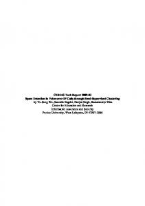
The Codec Adaptation Algorithm (CAA) is an algorithm based on real-time information gathered from the system, whose main function is to detect voice quality drops and react by proposing a new codec that is more efficient for the new cell conditions. The information needed for this process is gathered from the RTCP packets, which provide basic QoS metrics, such as delay, jitter and packet loss, as also from the MAC layer, which informs about rate changes the moment they happen. The algorithm can be implemented both in a centralized mode, installed in the Access Point as well as in a distributed mode, running on each node. Both implementations share the same basic core functions, with small changes between the two that will be explained later. For better understanding of the algorithm see also the block diagram depicted in Figure 3 and the flow chart presented in Figure 4. The basic CAA is composed of three main phases: the monitoring phase, including the MAC monitoring function and the RTCP filtering function, the adaptation phase, where all the calculations and decisions on codec change are made, and the recovery phase, where any codec change decided previously is negotiated and the results of the change are measured.
4.1
Monitoring
Starting with the monitoring phase, the two procedures, MAC and RTCP monitoring, work simultaneously, each one focusing on the problem from a different angle; while MAC monitoring provides a proactive mea-
6
surement, proposing to take action before any quality alarm arrives, RTCP monitoring responds to the alarm signals after they happen, in a reactive way. During the MAC monitoring the algorithm acts trying to prevent any QoS decrease, based on MAC layer information over rate changes. Since, as we have mentioned before, just one rate drop can provoke a big impact on all the calls of the cell, at the moment the node detects such event it perceives it as a potential alarm signal and can immediately drop to a lower codec, without waiting for any further signals from RTCP. This way we obtain faster response to situations that are most probably going to provoke a system degradation. In the following adaptation phase we can then determine if the codec drop was helpful enough or if we need to adjust the codecs further. Apart from achieving a faster response, this method is also very important so as to maintain the fairness of the algorithm. In other words, the node that suffers the rate change is the first to change codec and therefore is the first to suffer the consequences of its rate change, while the rest of the nodes may avoid even noticing any alarm and thus the need to adapt to it. Note that this function works equally well when there is an increase of the transmission rate instead of a decrease. This increase can be provoked analogous to the decrease (user moving closer to the AP, etc). In this case, the rate change is again detected during the MAC monitoring, and the node changes to a higher rate codec, to fully use its new rate and as a result, obtain better quality on voice transmission. After the codec change, we enter once more the adaptation phase to reassure there was no negative effect caused. On the other hand, the RTCP monitoring acts responding to QoS degradation signals obtained from filtering the regular RTCP packets arriving periodically to the node during a VoIP session. If the codec change invoked by the MAC layer was not enough to re-stabilize the situation on the cell or if some other cause (like wireless channel errors) is causing additional problems, then this will be detected in the RTCP filtering. The information obtained by the RTCP packets includes parameters critical for voice traffic, such as number of lost packets and end-to-end delay. These data are used, in order to calculate the R-factor of each flow (a real-time quality of service metrics proposed by International Telecommunications Union (ITU) [6]) using the calculations explained in the section 4.5. The equivalence of this factor to the most known Mean Opinion Score (MOS) can give us a first QoS metric for our system and define a decision threshold; if R-factor value falls below 70 (equivalent to MOS 3.6) the quality of the voice flow is not satisfactory and the algorithm triggers the adaptation phase for a new codec selection. This threshold, as also the thresholds used in the next phases of the algorithm, can be furthered tuned using more exhaustive simulations.
4.2
Adaptation
Passing to the adaptation phase, a random timeout is set, during which the algorithm requests from the node to send more RTCP packets in shorter intervals than the regular ones, in order to collect additional
7
codec selection
Voice Codec (Aplication layer) Codec adaptation algorithm
RTCP info
Data flow
(*)
MAC layer Data rate Data flow
(*) The algorithm does not change MAC parameters
Channel Status (DATA RATE)
Channel
Figure 3: Information flow for the proposed solution
information and make sure that the alarm situation was not due to any spurious error but still continues. The interval between the transmission of these ”fast RTCP packets” can be set accordingly to the needs of the algorithm and can be lower than the standard 5 seconds interval of RTCP transmission, as defined in the RTP extension for immediate feedback proposed in [15]. We have calculated an estimation of the total overload that these packets would introduce at the network. Based on a RTCP packet size of 90 bytes and setting the frequency of fast RTCP transmit at 1 second the overhead provoked by the control traffic is very small compared with the data traffic of a VoIP call using G.711 codec, with the control traffic occupying only 1.2% of the total traffic generated per user, way less than the allowed 5% for control traffic according to the RTP/RTCP standard. The timer set at the beginning of this phase is necessary in order to ensure that the nodes will not all react simultaneously, even if all of them perceive the alarm signals at the same instant. This way, we avoid the change of codec for more calls than necessary and give some time to the system to recover after every codec change. Additionally, the timer also serves as a period during which a minimun of N fast RTCP packets (with N set to 3 in the simulations) can be exchanged so as to have a big enough sample to help the algorithm quantify the problem efficiently. When the timer expires and using the information collected during this time, the algorithm calculates the average of the R-factor and from there the MOS, as also the average of packet loss and delay. CAA compares the average values as also the current values of the parameters after the timeout with a set of thresholds, chosen using the common values of permitted QoS parameters for an acceptable voice transmission (delay < 150ms, packetloss < 3%, R > 70). From the result of this comparison and the codec used untill now in the transmission, the node can choose a new codec, using the following procedure (see also Algorithm 1): a) if the average value of the parameter is out of threshold then check its current value; if the current value is also out of threshold propose a codec of α steps lower in the codec ranking else propose a β steps lower
8
codec. This way, even if the average performance of the call was not satisfactory during the fast monitoring time, if some other call has meanwhile changed codec and the system is beginning to recover (so the current value is above the threshold) then the call will suffer a smaller codec drop. b) if the both the average and the current value of the parameter are above the thresholds then there is no need to change codec. This check is performed for each one of the three parameters (delay, loss, R) used in the evaluation and an average of the proposed codec of the three is chosen. Note that α > β, with α = 2 and β = 1 in the simulations, and that the codecs are ordered based on their bit rates, as shown in Table 2. Algorithm 1 Adaptation phase while timer 6= 0 do fastRTCP monitoring paramN ow ⇐ current values of delay, loss, R for param ⇐ delay, loss, R do paramAvg ⇐ calculate average of parameter end for timer ⇐ timer − 1 end while for param ⇐ delay, loss, R do if paramAvg > paramT hreshold then if paramN ow > paramT hreshold then change(param) ⇐ α else change(param) ⇐ β end if else change(param) ⇐ 0 {No drop} end if end for changeT otal ⇐ Σ(change(param))/3 newCodec ⇐ drop(currentCodec, changeT otal)
4.3
Recovery
After the new codec selection, the node is responsible for issuing and sending a re-Invite SIP message to the other end, so as to renegotiate the new call characteristics. If the other end accepts the new codec the call continues normally, otherwise the call is dropped. Another issue could arise if the codec proposed as the most appropriate is lower than the lowest codec that a node can support. In this case one approach would be for the call to continue as it is during some standby time, without any codec change. If during this time some other node changes codec and the problem is solved then the call can continue successfully, otherwise the call will be dropped. Especially in the centralized version, the Access Point can choose to change another call if a slow codec call cannot change any further. Although this way we would avoid a call drop, this extra waiting time would introduce more delay in the
9
&#
"
"
&#
! !
' β
"
!
β "
$ !
#
!
%
#
β
α
!
Figure 4: Algorithm Flow Chart recovery process. This part of the algorithm has not yet been tested thoroughly and is part of our ongoing work. When the negotiations are over, a recovery flag is set to indicate that we are still evaluating the changes proposed by the adaptation phase. The algorithm continues to monitor the system using the fast RTCP messages and evaluate its performance; if the parameters are higher than the upper thresholds then we can return to the normal monitoring phase, else we need to go back to the adaptation phase and perform all necessary changes until we reach acceptable QoS levels.
4.4
General remarks
One important parameter of the proposed solution is the total delay of the process. Although this delay is not as critical as in other environments, since the call is not interrupted during the process, it is essential to be able to recover from the network changes and their negative effects as fast as possible. Otherwise, the call would be interrupted by the user. The total delay, from the moment that the rate change begins to affect the calls until the moment that the system recovers, depends mainly on the interval of RTCP packet transmission, since the random time is also set depending on the frequency of RTCP packets arrival.That is, 10
the random waiting time cannot be less that the time needed for a minimum number of RTCP packets to arrive, in order to have an appropriate sample size to permit the algorithm to evaluate the system correctly. This is in fact the reason why we chose to use the extended version of RTCP, since in the normal version the packet interval cannot be less than 5 seconds. Other factors that may influence the delay are the re-Invite process and the processing time of the algorithm; but in both cases these delays are negligible in comparison with the RTCP delay. Overall, the delay should not be more than a few seconds (e.g. less than 5), which is acceptable from the point of view of human perception and taking into account that during this time the call is not dropped. From the simulations below and choosing a frequency of 1 second for RTCP interval, we have obtained that the delay is in fact not more than 3 − 4 seconds, which can be actually seen using a higher zoom in one of the Figures 6 and 7. As we can see in Figure 4 the algorithm triggers and controls the adaptation phase based on a comparison of certain communication quality parameters against a set of thresholds. These quality parameters are derived from the real time calculation of the R-factor, which will be explained next.
4.5
E-Model Description
The E-Model is a planning tool for estimating the overall quality of a telephone network. ITU recommendation G.107 [6] introduced it with the objective to determine a quality rating that incorporated the ”mouth to ear” characteristics of a speech path. The output of an E-model calculation is a single scalar, called R factor, derived from delays and equipment impairment factors. Once the R factor is obtained, it can be mapped to an estimated MOS. The R factor can be obtained through the following expression:
R = Ro − Is − Id − Ie + A
(1)
where Ro represents the basic signal-to-noise ratio (SNR), Is represents the combination of all impairments which occur simultaneously with the voice signal, Id represents the impairments caused by delay, Ie represents impairments caused by low bit rate codecs, the so-called ”equipment impairment factor”, and A is the advantage factor, that corresponds to the user allowance due to the convenience in using a given technology. Equation 1 can be reduced to the following expression:
R = 93.4 − Id(T a) − Ie(codec, loss)
(2)
where Id is a function of the absolute one-way delay (Ta) and Ie is, in short, a function of the used codec type and the packet loss rate. Using the procedure described in [2] we can obtain the value of R in real-time from the data gathered from RTCP and the Ie table provided in [7].
11
After calculating the R factor, the equivalence between R and MOS can be determined as follows: 1 M OS = 1 + 0.035R + 7.10−6 R(R − 60)(100 − R) 4.5
R 100
By introducing a real-time calculation of the R-factor as a decision criterion in our algorithm, we obtain a more accurate and real time value of the MOS in which to base our decisions, compared with the traditional MOS value that has a fixed value for each specific codec.
5
Centralized vs Distributed Architecture
The codec selection algorithm can be implemented both in a distributed and in a centralized mode with small changes between the two implementations, but with visible difference in performance and results.
5.1
Distributed
In the distributed scenario, the algorithm is located on each node and each node monitors its own state. When a rate change is noticed on the MAC layer or based on the RTCP information that is arriving to it, the node is the one to determine whether or not to change codec. This is a more local approach and the node can only decide on the calls depending on it, which may not be the globally optimal solution. As we have proved in our previous work [18], there is no need for all calls to change codec at the same time, and changing slow-rate calls gives better results than changing fast-rate calls. This is due to slow-calls being the ones actually causing the problem, as seen in the problem statement. In the distributed implementation the algorithm cannot give priority to the slow calls, other than the one given by the proactive change, as the call that detects first the QoS drop will be the first to react. Additionally, since the control of the waiting timer is not centralized, more nodes can coincide and change simultaneously codec. Nevertheless, the distributed approach is easy to implement and it distributes the processing load of the algorithm.
5.2
Centralized
In the centralized case, the AP is in charge of monitoring all calls, the transmission rate of each flow and the codec used by each client. When a call passes from fast to slow then the AP, apart from changing the codec of it in a proactive way, can also determine which and how many other calls must change codec so as to reach network stability again, based on the RTCP information exchange between the clients. Intercepting the RTCP packets in their way from one end to the other, it calculates the instantaneous MOS value for all calls. When these values fall below the thresholds, the AP chooses the calls with the worst performance
12
and decides which calls to change and to which codec, giving more weight and priority in changing the slow calls first. Between each codec change, the Access Point waits during a random time, which permits that less number of calls will have to change. The drawback of this implementation is the amount of processing work for the AP. The Access Point must intercept all RTCP packets between the two ends of the voice flows and filter them to obtain the information it needs. When there is a codec change decision, it must inform the node that there is the need to change codec and therefore suggest to issue a SIP re-Invite message to renegotiate the codec with the other end. This can be more complicated than in the distributed version, but on the other hand there is a better overall monitoring of the whole network and there are more possibilities of achieving an optimal codec combination among the nodes. Simulation results show that there is an improvement in the performance of the algorithm when used in its centralized version; We have less calls changing codec, the packet loss percentage is almost zero and the overall MOS achieved is higher than in the distributed implementation. These results will be reviewed in the following section.
6
Simulation Results
For the simulations we have used the network simulator ns − 2 [12], having to modify its core modules in order to include the standard SIP agents (Proxy, UserAgent, and DNS ) to perform the basic SIP operations. The SIP patch was obtained from National Institute of Standards and Technology (NIST) [13] and we have adapted it for our ns − 2 scenario with the goal of controlling the codec of each call while the call is in progress. We have used the basic 802.11e MAC module obtained from [14] with the default parameters set and the experiments were performed for different channel rates, from 1 to 11 Mbps.
6.1
Scenario Description
The scenario we are considering is a hot-spot multirate scenario (Figure 5), where the network is composed by one 802.11e [5] basic service set with 9 wireless nodes and one Access Point connected to the wired network. The values of the parameters set used can be found in Table 1. A total number of 9 calls are active during the simulations, with all of them established between one wired and one wireless client, while the Access Point is also acting as a Proxy Server. All nodes start by using 11 Mbps data rate (fast-rate calls) and at predefined instants some flows change to 1 Mbps data rate (slow-rate calls). The calls are considered to start with the G.711 codec, have the same duration and change when needed to one of the lower bitrate codecs seen in Table 2. Monitoring frequency for the MAC monitor is f = 5 seconds, equal to the normal RTCP monitoring frequency. The fast RTCP transmission interval is one of the tunable parameters when using the extended RTCP version [15] and is set at δ = 1 seconds, in order to minimize the reaction time of the
13
R1 AP FAST CALLS
R2
SLOW CALLS MN
Figure 5: Multi-rate WLAN scenario
Table 1: System parameters of the IEEE 802.11b specification [4] Parameter Value Parameter Value Rdata {11, 5.5, 2, 1} M bps Rbasic {11, 5.5, 2, 1} M bps Rphy {1} M bps – CWmin 32 DIFS 50 µs SIFS 10 µs CWmax 1024 SLOT (σ) 20 µs m 5 EIFS 364 µs ACK 112 bits @ Rbasic RTS 160 bits @ Rbasic CTS 112 bits @ Rbasic MAC payload [0, 18496] bits @ Rbasic – MAC header 240 bits @ Rdata MAC FCS 32 bits @ Rdata PLCP preamble 144 bits @ Rphy PLCP header 48 bits @ Rphy Retry Limit (R) RS = 4, RL = 7 K (Queue length) 20 packets algorithm. We consider that all users support all codecs and there is no other traffic or other interferences in the wireless network. Each MN has a queue length of K = 50 packets. The AP coverage area A and radius R is composed of two regions: FAST and SLOW areas. The FAST area, AF is defined by a circle of radius R1 and the rest is defined as the SLOW area, AS (A = AF + AS ). Mobile Nodes are uniformly distributed through the coverage area, so with probability PF = AF /A the MN is in the FAST region and with PS = 1 − PF the SLOW region. Table 2: Codecs used Codec Bit rate MOS G.711 64Kbps 4.1 G.726 32Kbps 3.85 G.729 8Kbps 3.92 G.723.1 6.3Kbps 3.8
14
100
100 No algorithm Centralized algorithm Distributed algorithm
80 70 60 50 40 30 20 10 0
No algorithm Centralized algorithm Distributed algorithm
90 Agregated mean loss ratio (%) | Uplink
Agregated mean loss ratio (%) | Downlink
90
80 70 60 50 40 30 20 10
0
50
100
150 seconds
200
250
0
300
0
50
(a)
100
150 seconds
200
250
300
(b)
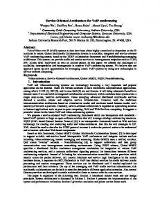
Figure 6: Average packet loss percentage (a) Downlink (b) Uplink
6.2
Analysis
We have tested both implementations of the algorithm: centralized, installed on the Access Point and distributed, running on each node. In order to understand the efficiency of the codec adaptation algorithm it is important to see what exactly happens to the network when no algorithm is present. When just two nodes start transmitting on a lower rate changing from 11 Mbps to 1 MBps (at instant t = 95 on Figure 6), the packet loss percentage gets quickly very high, with values reaching almost 90%, which can be translated to call drop since almost all packets are lost. Moreover, the packet delay increases to very high values reaching 1 sec, as the queue length becomes saturated (Figure 7). The congestion of the system, both in terms of loss and delay, is much more obvious in the AP, since it aggregates the traffic of all calls, this is why we observe the difference on the results between uplink and downlink. The AP, not being able to handle the new situation, acts as a bottleneck dropping queue packets and provoking a significant increase in packet loss ratio and delay. The resulted saturation can be also observed from the very low throughput obtained in Figure 9 and the low quality perceived by the user in the MOS calculation (Figure 8). The observed MOS, as calculated in real-time using the E-model, drops to values as low as 1, meaning communication breakdown according to the MOS standard definition. The situation is corrected only when one of the two nodes that previously dropped to a lower rate change again to a higher rate (11 Mbps) at simulation instant t = 200sec. After this point, we observe a decrease on delay and packet loss, although they remain higher than the desired for a correct VoIP transmission, with delay above 100ms and packet loss percentage of 10% in the downlink. The best solution is to lower the congestion level of the Access Point by reducing the codec of some of
15
1200
1200 No algorithm Centralized algorithm Distributed algorithm
No algorithm Centralized algorithm Distributed algorithm 1000 Agregated mean delay (ms) | Uplink
Agregated mean delay (ms) | Downlink
1000
800
600
400
200
0
800
600
400
200
0
50
100
150 seconds
200
250
0
300
0
50
100
(a)
150 seconds
200
250
300
(b)
4.5
4.5
4
4
Agregated mean opinion score (MOS) | Uplink
Agregated mean opinion score (MOS) | Downlink
Figure 7: Average Delay (a) Downlink (b) Uplink
No algorithm
3.5
Centralized algorithm Distributed algorithm
3
2.5
2
1.5
1
0
50
100
150 200 seconds
250
300
(a)
Centralized algorithm Distributed algorithm
3
2.5
2
1.5
1
350
No algorithm
3.5
0
50
100
150 200 seconds
250
300
350
(b)
Figure 8: Average MOS (Mean Opinion Score) obtained for all flows (a) Downlink (b) Uplink
the calls. In the distributed implementation of the algorithm, almost instantly as the rate changes happen at t = 95sec of the simulation, the nodes perceive the alarm situation and after a random waiting time they adapt to the network measurements by changing the codec. As we can see from the average throughput values obtained (figure 9), only some of the calls need to change codec and the transmission is re-stabilized very quickly, so while the total throughput may be lower than before the rate changes, since some calls now use codecs that require less bandwidth, the system is no longer saturated. This can be verified in the packet loss and delay figures, where there is just one peak of high loss percentage reaching 20% and high delay of around 200 ms at the moment of the transmission rate changes, which are corrected immediately. The effect 16
0.09
0.08
0.08 Agregated mean throughput (kbps) | Uplink
Agregated mean throughput (kbps) | Downlink
0.09
0.07 0.06 0.05 0.04 0.03 0.02
No algorithm Centralized algorithm
0.01 0
50
100
150 200 seconds
250
300
0.06 0.05 0.04 0.03 No algorithm
0.02
Centralized algorithm 0.01
Distributed algorithm
0
0.07
0
350
(a)
Distributed algorithm
0
50
100
150 200 seconds
250
300
350
(b)
Figure 9: Average throughput obtained for all flows (a) Downlink (b) Uplink
of the codec change observed in the packet loss ratio (figure 6) agrees completely with the one expected as explained in the problem statement. When using a lower bitrate codec, the offered load on the queue decreases and therefore we achieve less packet losses due to buffer overflow in the Access Point. The results of MOS come to justify our point that the user perceived quality is maintained at very high levels, with only an instant drop at the moment of the rate change and until the nodes start reacting. Even more impressive are the results of the centralized implementation. At the moment the MAC monitoring receives the rate change signal, it lowers by one the codec of the affected nodes. Along with this proactive codec change and by giving priority to the codec change on the calls that have suffered a rate drop, the total number of calls that need to change codec is lower than on the distributed implementation. This is evident from the total throughput obtained (Figure 9) which is higher than in the distributed mode, that is translated in more calls transmitting with higher bit rate codec. Again, both delay and packet loss results adjust to the expected performance as in the distributed implementation and even slightly better, with a peak at the moment of rate change which is fast corrected. During the rest of the time packet loss is practically 0 and delay remains on the order of a few milliseconds. The average MOS value, indicating the user perceived quality is maintained in very high values around 4.3, as can be seen in Figure 8, with only an instant drop at the moment of the rate change and until the nodes start reacting. This shows a huge gain compared to the MOS with value less than 1.5 achieved when no algorithm is present. Along with this proactive codec change, only one more codec change of a fast node’s call was needed during simulation, provoked from the RTCP monitoring, and the system recovers without noticing any of the negative effects mentioned above. This can be verified in the packet loss and delay figures, where we have just one peak of high loss percentage and high delay at the moment of the transmission rate change which 17
are corrected very fast. During the rest of the time packet loss is practically 0 and delay is no more than a few milliseconds. The average MOS value, indicating the user perceived quality is maintained in very high values around 4.3, as can be seen in Figure 8, with only an instant drop at the moment of the rate change and until the nodes start reacting. This shows a huge gain compared to the MOS with value less than 1.5 achieved when no algorithm is present. By giving priority to the codec change on the calls that have suffered a rate drop, we see that the total number of calls that need to change codec is lower than on the distributed implementation. This is evident from the total throughput obtained (Figure 9) which is higher than in the distributed mode, that is translated in more calls transmitting with higher bit rate codec. In fact, in this example just one call changing codec was sufficient to correct the problem. This is because since the slow calls are the ones blocking the others, it is more efficient to lower the codec of these calls, apart from also being the most fair solution. Again, both delay and packet loss results adjust to the expected performance as in the distributed implementation and even slightly better. As can be seen from the results, both implementations of the CAA give satisfactory performance, since no calls are being dropped, there is a fast reaction and correction of the quality degradation and there are minimal packet losses with high average MOS obtained. Comparing the centralized with the distributed implementation, it becomes clear that the centralized gives better results as expected, since the Access Point has an overall control of the nodes and the codec they use and provides a more efficient combination of codecs. On the other hand, this means more processing effort for the Access Point and the results on the distributed method are quite satisfactory and give an interesting and almost equally effective alternative to the centralized version. The results presented in this paper were compared against an analytical model presented in [1]. The system behavior was shown to match quite precisely the expected results, as foreseen by the analytical model.
7
Conclusions and Future Work
In this work, we analyzed the problem of a multi-rate environment on the voice over IP service and we proposed a codec adaptation algorithm using cross layer information from MAC and RTCP packets to solve it. Our algorithm can be implemented both in a centralized and in a distributed way, and as performance simulation results show, it can solve efficiently and fast the quality degradation provoked to the calls due to the rate changes, with no call drops, minimum packet losses and an average high MOS value. There are still other aspects to be considered. The implementation of a CAC (Call Admission Control) in a 802.11e scenario is the next step, in order to evaluate this solution on an environment guaranteeing QoS
18
for voice streams. The further testing of the different versions of the algorithm (centralized/distributed) and particulary their cooperation with an Admission Control technique is a big challenge. We believe that the combination of the two techniques can help improve the performance of both and provide interesting results. Note that, in that case, the codec change option might be also due to traffic overload in spite of good channel conditions for all calls, allowing a higher number of simultaneously calls and so, reducing the blocking / dropping probability. More experiments with other type of multimedia traffic will be considered, as also high load scenarios with TCP traffic co-existence. The actual implementation and testing of the algorithm on a real testbed is also of great interest. Finally, another future research line is the integration of this work in an IMS (IP Multimedia Subsystem) architecture where new elements, such a voice transcoder server, are also considered.
19
References [1] Bellalta, B., Meo, M., Oliver, M.; A BEB-based Admission Control for VoIP calls in WLAN with coexisting elastic TCP flows, NEW2AN06. St. Petersburg, Russia, June 2006. [2] Gardner M., Frost V., Petr D.: Using Optimization to Achieve Efficient Quality of Service in Voice over IP Networks, IEEE IPCCC (2003) [3] Heusse M., Rousseau F., Berger-Sabbatel G., Duda A.; RTP: Performance Anomaly of 802.11b, Proc. of IEEE INFOCOM 2003, San Francisco, USA, 2003. [4] IEEE Std 802.11; Wireless LAN Medium Access Control (MAC) and Physical Layer (PHY) specifications, ANSI/IEEE Std 802.11, 1999 Edition (Revised 2003) [5] IEEE Std 802.11e; Wireless LAN Medium Access Control (MAC) and Physical Layer (PHY) specifications; Amendment: Medium Access Control QoS enhancements, IEEE Std 802.11e, 2005 [6] ITU-T Recommendation G.107, ”The E-model, a computational model for use in transmission planning”, (2000) [7] ITU-T Recommendation G.113, ”Transmission impairments due to speech processing”, Pre-Published Recommendation, (2001). [8] Jiwoong J., Sunghyun C., Chong-kwon K.; Achieving Weighted Fairness between Uplink and Downlink in IEEE 802.11 DCF-Based WLANs, IEEE QShine’05, Orlando, USA, August 2005 [9] Lundberg, T.; de Bruin, P.; Bruhn, S.; Hakansson, S.; Craig, S; Adaptive thresholds for AMR codec mode selection, IEEE, VTC Spring 2005, Stockholm, Sweden. [10] Manousos, M. et al.; Voice-Quality Monitoring and Control for VoIP, IEEE Internet Computing, July-August 2005 [11] McGovern P., Chung S., Murphy S., Murphy L.; Endpoint Admission Control for VoIPoWLAN, Proc. of ICT 2006, Funchal, Madiera Island, Portugal, May 2006. [12] Network Simulator-2; http://www.isi.edu/nsnam/ns/, Version 2.28 [13] ns-2 SIP patch, National Institute of Standards and Technology (NIST) [14] ns-2 802.11e patch, Telecommunication Networks Group, Technical University of Berlin, Germany [15] Ott et al.; Extended RTP Profile for RTCP-based Feedback (RTP/AVPF), Internet Draft, August 2004
20
[16] Qiao Z., Sun L., Heilemman N., Ifeachor E.; A new method for VoIP Quality of Service control use combined adaptive sender rate and priority marking, IEEE ICC’04, June 2004, Paris [17] Schulzrinne, H., Casner, S., Frederick, R., Jacobson, V.; RTP: A Transport Protocol for Real-Time Applications, RFC 3550, IETF standard, July 2003 [18] Sfairopoulou A., Maci´an C., Bellalta B.; QoS adaptation in SIP-based VoIP calls in multi-rate IEEE 802.11 environments, IEEE ISWCS ’06, Valencia, Spain, September 2006 [19] Toshihiko T., Tadashi I.; Wireless LAN Resource Management Mechanism Guaranteeing Minimum Available Bandwidth for Real-time Communication, IEEE WCNC 2005, New Orleans, USA, March 2005 [20] Trad A., Ni Q., Afifi H.; Adaptive VoIP Transmission over Heterogeneous Wired/Wireless Networks, 2nd International Workshop on Multimedia Interactive Protocols and Systems (MIPS 2004), Grenoble, France, November 2004.
21