evaluating G and D of soil, especially at large shear strains. Results of truly undrained and conventional constant-volume tests by using a developed NGI direct ...
DYNAMIC PROPERTIES OF SAND IN CONSTANT-VOLUME AND CONSTANT-LOAD TESTS Jafarzadeh, F. Sharif University of Technology Tehran, Iran 11365-9313
Sadeghi, H. Sharif University of Technology Tehran, Iran 11365-9313
ABSTRACT Constant-volume and constant-load tests were performed on Babolsar and Toyoura sands by using a modified SGI cyclic simple shear device which provides the capability of back pressure saturation. All tests were shear strain controlled and conducted under different values of relative density, vertical effective stress and shear strain amplitude. Results revealed that Dr, σ′v and γ affect shear modulus and damping ratio under both constant-volume and constant-load conditions in similar ways except the shear strain amplitude which has no important influence on damping of constant-volume tests. The effects of Dr, σ′v, γ and the number of cycles on variations of shear modulus and damping ratio of sand were found to be more pronounced under constant-load condition. It seems that the differences between the results may be due to the different fabric produced in two kinds of test samples rather than to the test method. However, further study is needed to clarify this issue. INTRODUCTION
Results of truly undrained and conventional constant-volume tests by using a developed NGI direct simple shear device were compared by Dyvik et al. 1987. On the basis of static tests on clay, they concluded that the results obtained by two methods are equivalent for saturated soils. Theoretically, since there is no real pore pressure generation in the specimen under constant-volume condition, it is not necessary to saturate the specimen. However, poor saturation can modify soil resistance (Vanden Berghe et al. 2001). The main objective of the present study is to investigate shear modulus and damping ratio of cyclically loaded sand under constant-volume and constant-load conditions. Additionally, the effects of some parameters on dynamic properties of sand under mentioned conditions will be presented and discussed.
Paper No. 1.11a
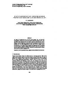
LABORATORY PROCEDURE Test Materials Two poorly graded sands, Babolsar and the Japanese standard Toyoura sand were selected as test materials. The former is natural sand obtained from the South coast of Caspian Sea. Particle size distribution curves of sands are shown in Fig. 1.
Silt 100 90 80 70 60 50 40 30 20 10 0
Sand Fine
Medium
Coarse
Gravel
Babolsar sand
Finer by weight (%)
Wide application of dynamic properties of soil in geotechnical earthquake engineering problems (such as the analysis of soilstructure interactions, dynamic bearing capacity of machines foundations, soil structures subjected to cyclic loadings) has made researchers to investigate a variety of factors which affect shear modulus and damping ratio of soil (e.g. Hardin and Drnevich 1972a) and to develop various field and laboratory tests methods so far (Kramer 1996). A cyclic simple shear test is a convenient laboratory test method in evaluating G and D of soil, especially at large shear strains.
Toyoura sand ASTM Babolsar Toyoura D422-63
0.01
D 10
0.14
0.14
D 30 D 50
0.22 0.25
0.16 0.19
Uc
1.79
1.56
Cc
1.32
0.95
0.1 1 Particle size (mm)
10
Fig. 1. Gradation curves of test materials.
1
Principal index tests were performed following the procedure of the ASTM standards. The physical properties of soils utilized in the all conducted tests are summarized in Table 1. Table 1. Physical properties of test materials Soil type Babolsar sand Toyoura sand Standard designation
Specific gravity 2.753 2.645 ASTM D854–02
emax emin 0.777 0.549 0.973 0.609 ASTM ASTM D4254–00 D4253–00
Apparatus
De -ai red
wa ter
A servo-controlled pneumatic SGI cyclic simple shear, CSS; apparatus manufactured by Wykeham Farrance Co. was used in order to perform the cyclic loading of soil samples. This apparatus is capable of conducting stress and strain controlled tests in the both horizontal and vertical directions. Loading forces are applied through the pneumatic actuators mounted horizontally and vertically. A circular specimen is mounted between the base pedestal and piston top cap and surrounded by a number of circular rings to prevent lateral displacement during consolidation or shearing stages. Indeed, the specimen can be laterally restrained by rigid boundary plates (Cambridge-type device), a wire-reinforced membrane (NGItype device), or a series of stacked rings (SGI-type device) according to the description of Kramer 1996.
The apparatus was equipped with a pressure test device made by ELE. The pressure test device which can introduce water pressure into the specimen was utilized in order to improve the apparatus so that it can be used in conducting undrained tests on fully saturated samples. On the other hand, the capability of saturating the specimen with back pressure has been possible using this ancillary device. A schematic illustration of the modified CSS apparatus is given in Fig. 2. Sample Preparation Constant-Volume Tests. Solid cylindrical samples with the nominal diameter of 70 mm and height of 22 mm were used in cyclic simple shear tests. Samples were prepared by using the moist placement method suggested by Ishihara 1996. The mixture of soil with 5% water content was poured in the mold with a spoon and the specimen was compacted until approaching the desired density. The relative density of the specimen was controlled by adjusting its height using a 0.01 mm digital caliper. This method of sample preparation was utilized in constant-volume and constant-load tests. Estimation of Pore Pressure Parameter. Use of Skempton’s pore pressure parameter, B value; in triaxial loading condition as a guide to achieve full saturation is conventional but, for the stress conditions other than triaxial condition e.g. where the specimen is consolidated under K0 condition (Fig. 3a), there is no criteria for assuring full saturation of the sample. It seems that a proper evaluation of pore pressure parameter under this special loading condition is inevitable. The pore water pressure increment under undrained conditions due to applying major, intermediate and minor principal stresses to a saturated soil element (Fig. 3b), was suggested by Henkel 1960 as: ∆u
∆σ a
3a∆τ ∆σ
∆σ
∆σ
∆σ ⁄3
∆σ
∆σ
∆σ
∆σ
∆σ
(1)
where ∆σoct and ∆τoct are the increases in the octahedral normal and shear stresses and a is Henkel’s pore pressure diameter. Accordingly, the increase of pore water pressure under stress conditions represented in Fig. 3a, will be: ∆u
∆σ 1
2K ∆σ ⁄3 2K ⁄3
a√2 ∆σ
a√2 1
K
∆σ
K ∆σ (2)
where K0 is the at-rest earth pressure coefficient. For uniaxial stress condition as shown in Fig. 3(c), we can substitute ∆σ1∆σ3 for ∆σ1 and zero for ∆σ2 and ∆σ3 in equation 1 which will yield: Fig. 2. Schematic view of cyclic simple shear (SGI type) apparatus and pressure test device.
Paper No. 1.11a
∆u
∆σ 1⁄3
∆σ ⁄3 a√2
∆σ1
a√2 ∆σ ∆σ3
∆σ (3)
2
∆u⁄∆σ
Δσ 1
(a)
Δσ 3 = K 0 Δσ 1
Δσ 2 = K 0 Δσ 1
Δσ 2 = K 0 Δσ 1
Δσ 1
Δσ3
K
Δσ 3
Δσ 1 Δσ 1 − Δσ 3
(c)
1⁄3 1
K
(6)
1
sinφ
(7)
1
sinφ
5.5
γ ⁄γ
1
(8)
The coefficient of at-rest earth pressure was calculated by using Equations 7 and 8 where A and φ are supposed to be 1/3 and 30˚; respectively. The pore pressure parameter, ∆u/∆σ1, values were then estimated according to Equation 6 for two kinds of sand with 30 and 70% relative density and reported in Table 2. Based on the results of Table 2 it seems that, Equation 8 overestimates the values of K0 which consequently results in miscalculation of ∆u/∆σ1. It may be concluded that the pore pressure parameter, ∆u/∆σ1, for this special stress conditions presented in Fig. 3a ranged between 0.67 and 1.0 but, more laboratory studies are also needed. Traditionally, the value of pore pressure parameter under triaxial stress conditions, B value, equals to 0.95 is accepted as representing virtually full saturation in laboratory reports. As an alternative, if several successive equal increments of confining pressure give identical values of B, full saturation of the specimen could be assured (Head 1998).
Δσ 2
Δσ 2
A
where φ is the internal friction angle of soil. Sherif et al. 1984 pointed out that Equation 7 is only applicable if the soil is deposited at its loosest state. Considering the overcompaction effects, they proposed Equation 8 for evaluating the at-rest earth pressure coefficient:
Δσ 1
(b)
2K ⁄3
which is the pore pressure parameter under stress conditions shown in Fig. 3a. According to Equation 6, if a representative value of A and K0 can be determined, the pore pressure parameter, ∆u/∆σ1, can be estimated. The coefficient of at-rest earth pressure, K0, can be measured by the well known Jaky equation (Jaky 1944) as follows: K
Δσ 3 = K 0 Δσ 1
1
Table 2. Estimated ∆u/∆σ1 based on Henkel’s modification Δσ 1 − Δσ 3
Fig. 3. Saturated soil element consolidated under (a) K0 condition, (b) three principal stresses, (c) uniaxial condition. On the other hand, the increase of pore water pressure due to undrained uniaxial loading ∆σ1-∆σ3 as applied in Fig. 3c, can be proved (Das 1983) is ∆u
A ∆σ
∆σ
(4)
where A is the Skempton’s pore pressure parameter. A comparison of equations 3 and 4 gives: A
1⁄3
a√2
Finally, substituting
Paper No. 1.11a
a
A
1⁄3 ⁄√2
Dr (%) Babolsar 30 Babolsar 70 Toyoura 30 Toyoura 70
Sand type
(5)
from equation 5 to equation 2, we have:
γd (kN/m3) 15.80 16.69 13.92 15.10
∆u/∆σ1 ∆u/∆σ1 K0 Eq. (8) Eqs. (6) & (7) Eqs. (6) & (8) 0.72 0.67 0.81 1.04 0.67 1.03 0.82 0.67 0.88 1.32 0.67 1.21
Constant-Load Tests. After preparation of samples on the basis of wet tamping method, CO2 was percolated through the specimens and de-aired water was then introduced into the soil sample, while the vertical stress was kept at 15 kPa to prevent the sample disturbance. After one stage of saturation using 25 kPa of vertical stress and 15 kPa of back pressure was taken, back pressure was raised following the vertical stress increase to the next step by 10 kPa and the procedure of raising the vertical stress and back pressure was then repeated. Considering the mentioned criteria for assuring full saturation, the saturation of the specimens by the application of back pressure was continued until two or three equal increments of
3
vertical stress give identical values of pore pressure parameter, ∆u/∆σ1. The samples were then consolidated to a given vertical consolidation stress. The values of total vertical stress, effective consolidation stress and back pressure as well as the corresponding ratio of pore water pressure parameter, ∆u/∆σ1, at the last step of saturation for 16 undrained tests are summarized in Table 3. Table 3. Measured ∆u/∆σ1 in constant-load tests at the end of saturation stage σv Back pressure Dr (%) (kPa) (kPa) 9 (B*) 31 175 125 10 (B) 35 175 125 11 (B) 71 205 155 12 (B) 67 205 155 13 (B) 32 275 125 14 (B) 30 275 125 15 (B) 74 305 155 16 (B) 71 305 155 25 (T**) 32 175 125 26 (T) 33 175 125 27 (T) 71 205 155 28 (T) 70 205 155 29 (T) 28 275 125 30 (T) 39 275 125 31 (T) 68 305 155 32 (T) 70 305 155 B*: Babolsar sand, T**: Toyoura sand Test no.
σ′v ∆u/∆σ1 (kPa) 50 0.90 50 0.88 50 0.88 50 0.88 150 0.89 150 0.87 150 0.90 150 0.89 50 0.91 50 0.90 50 0.88 50 0.85 150 0.86 150 0.91 150 0.82 150 0.83
Test Program Whereas the after consolidation relative density should be taken into account, a series of calibration consolidation tests were conducted to specify the initial relative density of the partially and fully saturated specimens. The values of initial Dr for different vertical σ′v and post consolidation relative densities as results of preliminary tests are reported in Table 4. The main experimental program included tests with different values of σ′v, Dr and γ which were performed under constantvolume and constant-load conditions. Unsaturated samples were sheared under equivalently undrained or constantvolume condition. On the other hand, truly undrained tests were carried out on fully saturated specimens under constantload condition. Half of the specimens were consolidated to 50 kPa and the others to 150 kPa. Test samples had two different post-consolidation relative densities 30, 70% representing loose and medium dense conditions; respectively. All tests were shear strain-controlled with an approximately sinusoidal shape of cyclic straining at large shear strain amplitudes of 1.0 and 1.5%. The frequency of cyclic loading was 0.5 Hz and the number of loading cycles varied from 1 to 200 or to the cycle of initial liquefaction, which ever occurred first. General testing conditions at the beginning of cyclic shear stage are listed in Table 5 for 32 cyclic simple shear tests.
Paper No. 1.11a
Table 4. Preliminary tests results Post σ′v Initial Dr consolidation (kPa) (%) Dr (%) P1–B* Constant-volume 30 50 23.2 P2–B Constant-volume 70 50 64.9 P3–B Constant-volume 30 150 16.6 P4–B Constant-volume 70 150 59.5 P5–B Constant-load 30 50 3.5 P6–B Constant-load 70 50 57.9 P7–B Constant-load 30 150 – 3.7 P8–B Constant-load 70 150 52.0 P9– T** Constant-volume 30 50 25.0 P10–T Constant-volume 70 50 65.7 P11–T Constant-volume 30 150 20.5 P12–T Constant-volume 70 150 62.1 P13–T Constant-load 30 50 4.5 P14–T Constant-load 70 50 62.7 P15–T Constant-load 30 150 – 1.7 P16–T Constant-load 70 150 58.3 B*: Babolsar sand, T**: Toyoura sand Test no.
Test condition
Table 5. Tests conditions at the beginning of cyclic stage Sand Vertical load type condition 1, 2 B* Constant-volume 3, 4 B Constant-volume 5, 6 B Constant-volume 7, 8 B Constant-volume 9, 10 B Constant-load 11, 12 B Constant-load 13, 14 B Constant-load 15, 16 B Constant-load 17, 18 T** Constant-volume 19, 20 T Constant-volume 21, 22 T Constant-volume 23, 24 T Constant-volume 25, 26 T Constant-load 27, 28 T Constant-load 29, 30 T Constant-load 31, 32 T Constant-load B*: Babolsar sand, T**: Toyoura sand Test no.
Dr (%) 32, 29 69, 69 29, 30 70, 69 31, 35 71, 67 32, 30 74, 71 31, 29 70, 69 29, 30 69, 69 32, 33 71, 70 28, 39 68, 70
γ (%) 1.0, 1.5 1.0, 1.5 1.0, 1.5 1.0, 1.5 1.0, 1.5 1.0, 1.5 1.0, 1.5 1.0, 1.5 1.0, 1.5 1.0, 1.5 1.0, 1.5 1.0, 1.5 1.0, 1.5 1.0, 1.5 1.0, 1.5 1.0, 1.5
σ′v (kPa) 50 50 150 150 50 50 150 150 50 50 150 150 50 50 150 150
Calculation of G and D Dynamic stiffness and damping ratio of each cycle can be determined from a graph of stress against strain, knowing as hysteresis loop. Figure 4 illustrates a schematic hysteresis loop and how secant modulus and damping can be determined based on data achieved from stress-strain curve. By using 50 data point per cycle which transferred through CDAS to PC, the area of hysteresis loop can be estimated precisely according to Equation 9.
4
20
-10
-2
-1
0
1
2
Shear Strain (%) (
γ max
γ τ
γ τ
γ τ
γ τ
(9))
in whhich Aloop is thhe area of hyssteresis loop with w vertices off (γ1, τ1), (γ2, τ2)…(γγ50, τ50) and γi, τi are shear sttrain and shearr stresss at ith point; respectively. r Jaafarzadeh and Sadeghi 20099 indicaated that the algorithm a can also a be used inn estimation off dampping ratio underr drained cond dition. Typiccal Test Resultts Typiccal results of constant-load c and a constant-voolume tests aree illustrrated in Fig. 5.. Figure 5a sho ows the resultss of a constant-load test t (Test #11)) conducted on n a sample withh 70% relativee density and 50 kPaa vertical effecctive stress. Thhe shear strainn ampliitude was 1.0% %. Typical resu ults of Test #244 on a medium m densee sample withh 150 kPa con nsolidation strress and 1.5% % shearr strain amplittude under con nstant-volume condition aree also presented p in diagrams d of Fig. 5b. Figure 5 contains thee variattions of shear stress, shear modulus and damping ratioo with the number of cycles along g with the shear stress-strainn curvees.
-10 10 20 30 Number of Cyycles
2000
40
50 40
Sheaar Modulus
1500
30
Dam mping Ratio
1000
20
500
10
0
0 0
10
(a)
20
30
40
50
Number of Cycles 30 First Cycle Test # 24, Toyoura sand, σ'v =150 kPa, γ=1.5 %, Dr=70 %, Uunder Constant-Volume condition
γ τ
0
0 Shear Modulus, G (kPa)
Fig. 4. Estimation of G and D fro om data of a hyysteresis loop.
10
-20
Shear Stress (kPa)
τ γ min
Aloop ΔW = 2πW 2πGsec[(γ max − γ min ) 2]2
10 -10 -2
-1
0
1
2
-30 Shear Strain (%) (
Shear Stress, τ (kPa)
D=
Shear Stress, τ (kPa)
20
τ c τ γ max − τ γ min Gsec = s = γ c γ max − γ min
γ 0.5 τ
0
-20
γ min
A
Test # 11, Babolsar sand, σ'v =50 kPa, γ=1.0 %, Dr=70 %, Uunder Constant-Load condition
1
W
First Cycle
10
Damping Ratio, D (%)
ΔW
Shear Stress (kPa)
Gsec
τ γ max
30 20 10 0 -10 -20 -30 0
10
20
30
40
50
Figurres 6 and 7 shoow the variation ns of shear moodulus with thee numbber of cycles foor two tested materials. m Resuults of the testss performed under 500 kPa vertical effective e consoolidation stresss repressented in Fig. 6 while Fig. 7 includes thee data obtainedd from the other tests with 150 kPa k vertical efffective stress. Sampple specificatioon and testing g conditions arre also plottedd abovee each chart. These T figures compare c dynam mic stiffness off soil specimens unnder constant--volume and constant-loadd condiitions. Accordiing to the resu ults, shear moddulus decreasess
Paperr No. 1.11a
1500 1000
20
500
15
0
10 0
(b)
25
Sheaar Modulus Dam mping Ratio
10
20
30
40
Damping Ratio, D (%)
Effecct of Number of Cycles
Shear Modulus, G (kPa)
Number of Cyycles
RESU ULTS AND DIISCUSSION
50
Number off Cycles
Fig. 5. Typical resuults of a (a) connstant-load tesst, (b) constanttvolume test.
5
3500 σ′v=50 kPa, γ=11.0 %, Dr=30 %
B-C-V B-C-L
B: Bab bolsar T: Toy youra C-V: Constant-volume C e C-L: Constant-load C
1 1200 800
Shear Modulus, G (kPa)
Shear Modulus, G (kPa)
1 1600
T-C-V T-C-L
400 0
σ′v=150 kPa, γ= =1.0 %, Dr=30 %
B-C-V
B: Baabolsar T: Toyoura C-V: Constant-volum me C C-L: Constant-load
B-C-L
2 2800 2 2100 1400 700
3
6
9
12
15
0
5
10
Numberr of Cycles
20
25
30
2 2500 σ′v=50 kPa, γ=1 1.5 %, Dr=30 %
B-C-V
Shear Modulus, G (kPa)
Shear Modulus, G (kPa)
15
Number of Cycles
1 1200 B-C-L
900
T-C-V 600
T-C-L
300 0
σ′v=150 kPa, γ= =1.5 %, Dr=30 %
B-C-V
2 2000
B-C-L
1500
T-C-V T-C-L
1000 500 0
0
2
4
6
8
10
0
3
Numbeer of Cycles
6
9
12
15
Number of Cycles
2 2000
4 4000 σ′v=50 kPa, γ=1 1.0 %, Dr=70 %
B-C-V
Shear Modulus, G (kPa)
Shear Modulus, G (kPa)
T-C-L
0 0
B-C-L
1 1500
T-C-V 1 1000
T-C-L
500 0
σ′v=150 kPa, γ= =1.0 %, Dr=70 %
B-C-V
3 3200
B-C-L
2 2400
T-C-V T-C-L
1 1600 800 0
0
10
20
30
40
0
50
30
Numbeer of Cycles
60
90
120
150
Number of Cycles
1 1800
3500 σ′v=50 kPa, γ=1 1.5 %, Dr=70 %
1 1500
B-C-V
Shear Modulus, G (kPa)
Shear Modulus, G (kPa)
T-C-V
B-C-L
1 1200
T-C-V
900
T-C-L
600 300 0
σ′v=150 kPa, γ= =1.5 %, Dr=70 %
3000
B-C-V B-C-L
2 2500
T-C-V
2 2000
T-C-L
1500 1000 500 0
0
7
14
21
28
35
Numbeer of Cycles
Fig. 6. Variations of o shear modullus with the num mber of cycles for sppecimens conssolidated to 50 kPa vertical efffective stress.
Paperr No. 1.11a
0
10
20
30
40
50
Number of Cycles
Fig. 7. Variations of shear modulus with the nuumber of cycless for sppecimens consolidated to 1500 kPa vertical effective stresss.
6
The trends t of sheaar modulus variations with the t number off cycles are similar under the both b truly andd equivalentlyy undraained conditionns but, the valu ues differ from m each other too some extent. The values v of shearr modulus at cycle c 1 for alll samples sheared unnder constant-load condition are more thann the coorresponding values v of constaant-volume tessts. In addition, in conntrast to a specific constant-volume test, loower values off dynam mic stiffness are obtained for the corressponding fullyy saturaated sample unnder constant-lo oad condition after it reachess to thhe cycle of initial i liquefaction and losses its laterall resisttance to shear stresses. It means that the range r of shearr moduulus variationss with the num mber of cyclees under trulyy undraained conditioons is higher compared to the constant-volum me tests while the number off cycles varies between 1 andd N l. Althoough both speccimens for con nstant-volume and constant-load tests t were preppared by wet taamping and hadd same relativee densities at the beeginning of cyclic c stage, the t specimenss shearred under connstant-load co ondition seem m to be moree homoogenous because of the wateer flushed into the specimenss during saturation stage. s The watter lubricates the surface off grainss and makes the t movementt of grains on each other inn desiraable directionss easier. So it would w appear that, t the higherr valuee of shear modulus m at cy ycle 1 under constant-loadd condiition comparedd to the constan nt-volume tests is because off the more m homogennous fabric produced for fully f saturatedd samples than unsaaturated samp ples prepared for constant-volum me tests. As shhown previously in Figs. 6 and a 7, the valuues of dynamicc stiffness obtained through the constant-load tests are lesss r of constant-volume tests after thee comppared to the results specim mens reach to the initial liquefactionn. A possiblee explaanation for thee higher values of shear modulus m underr consttant-volume condition may y be the resiidual strengthh remaiined in the speecimens after liquefaction l duue to the inter-granuular suction forrces. Indeed th he water contennt of about 5% % whichh is mixed withh dried sand makes m the placeement of moistt sand in a very loosse structure po ossible, becausse of capillaryy effectts between paarticles (Ishihaara 1996). Thhis amount off waterr remains in thhe sample as well as the capillary forcess betweeen grains evven after thee occurrence of imaginaryy liqueffaction. Thereffore, constant--volume tests represent r moree valuees of shear modulus in contrast to the consstant-load testss run on o the fully saaturated specim mens which coompletely losee their shear strength.. d off damping ratiio on the num mber of cycless The dependence underr constant-loadd condition is shown in Fig. 8. 8 Based on thee diagraams of Fig. 8 the t variations of damping with the numberr of cyycles can be neeglected up to 10th cycle before the initiall
Paperr No. 1.11a
45 40 35 30 25 20 15 10 5 0
Test No. 9 10 11 12 13 14 15 16
Babolssar 1
10 100 Numbeer of Cycles
(a)
1000
40 Damping Ratio, D (%)
with the number of cycles un nder all testiing conditionss indeppendent of verrtical load con ntrolling modee. In the otherr wordss, the excess pore water pressure deveeloped due too increaase in the num mber of cycles under u constant--load conditionn as well w as consttant-volume condition, c caauses stiffnesss degraadation.
Damping Ratio, D (%)
30 25 20 15 10 5
Toyourra
0 1 (b)
Test No. 25 26 27 28 29 30 31 32
35
10 Numberr of Cycles
100
Fig. 8. Variations of damping ratio with the nuumber of cycless for the tessts under consttant-load conddition. ward, dampingg increases subbstantially withh liqueefaction. Afterw the number n of cyclles. It means that t for the sam mples liquefiedd beforre 10th cycle, damping d valuess are in ascendding order from m cyclee 1. On the other o hand, forr samples liquuefied after 100 cyclees, the numbeer of cycles has a negliggible effect onn dampping variationss until 10 cyccles to Nl andd a significannt grow wth in dampinng ratio takes place in the last 10 cyclees beforre Nl. Results indicated thaat, the developped pore wateer presssure has an impportant influence on dampingg variations. In thhis study dampping values aree represented from f cycle 1 too Nl. By B getting closse to the cyclee of initial liquuefaction, sheaar strenngth of a speccific sample decreases d signiificantly whichh resullts in a signifiicant decrease in shear moddulus. Dampingg increeases with a decrease in shear moduulus until the occurrrence of initiial liquefactionn, according too Fig. 4. Afteer liqueefaction, the hoorizontal load cell c which direectly connectedd to thhe pneumatic actuator cannnot sense the lateral forcees preciisely. Therefoore, the shaape of hysteresis loop iis miscalculated alongg with the loopp area and sheaar modulus thaat subseequently makees damping raatio unreliable. So, it is jusst assum med that dampping values aft fter a sample is liquefied, are the saame as dampinng at Nl. Figurre 9 indicates the variations of damping ratio with the numbber of cycles for f all constannt-volume testss. As shown inn the diagrams d of Fig. F 9, dampinng ratio decreeases with the numbber of cycles. By B comparing the results of Figs. F 8 and 9, iit
7
Damping Ratio, D (%)
25 Babbolsar 22
Tesst No.
1 5
2 6
3 7
4 8
19 16 13 10 20
0 (a)
40 60 Number of Cycles
Damping Ratio, D (%)
26 Toyooura 23
Test No.
17 21
80
18 22
19 23
100
20 24
20 17 14 0
(b)
20
40 60 Number of Cycles
80
100
Fig. 9. Variations of o damping rattio with the num mber of cycles for the testss under constan nt-volume conddition. is infferred that thee trends of damping d variattions with thee numbber of cycles under constan nt-volume conndition are nott compparable with thoose of constantt-load tests. In contrast to thee consttant-load tests, damping will not increase by b approachingg to thhe cycle of innitial liquefacttion under coonstant-volumee condiition. It seemss that, the tests performed in the presentt studyy under constaant-load condittion represent more reliablee trendss for damping variations witth the number of cycles thann consttant-volume tessts. The main m reason foor rapid growtth in damping ratio with thee numbber of cycles by getting clo ose to the liquuefaction statee underr truly undraained conditio on was the low shearingg resisttance of specim mens to lateral forces which was correlatedd with the shear modulus. Subseq quently, the loower values off her values of damping ratioo shearr modulus resuult in the high (Fig. 4). But, undeer constant-volume conditionn the trends off dampping variationss with the num mber of cycless are different. Sincee the specimens were no ot fully saturrated and thee develloped pore watter pressure is imaginary i evenn after the totall verticcal load was omitted o from the specimen, there was ann amouunt of shear modulus m which was more in contrast to thee truly undrained testts. It means th hat the specim mens had shearr strenggth to the latteral load eveen after the occurrence off liqueffaction due to the capillary effects. e This residual value off shearr modulus prevvents damping from increase as in constant-load tests and keepps it nearly co onstant with a few scatteringg until cycle 100.
Paperr No. 1.11a
Effeccts of Dr, σ′v annd γ The tests t were connducted under two t different levels l of Dr, σ′′v and γ, γ while the otther testing conditions were kept the samee. So, the t effects of relative r densityy, vertical effecctive stress andd shearr strain amplittude on shear modulus and damping ratioo can be b investigatedd under constaant-volume andd constant-loadd condditions. Compaarisons will be b presented and discussedd basedd on the valuees of shear modulus and daamping ratio aat cyclee 5. Effecct of Relative Density. Figuure 10 indicatees the effect oof relatiive density on shear moduluus and dampingg ratio of sandd. The increase in sheear modulus as a a result of 40% 4 increase inn Dr caan be seen in Fig. F 10a for coonstant-volumee and constanttload tests. Legendss shown at thee right side off each diagram m contaain the numbbers of indivvidual tests. Complete tesst condditions were sum mmarized in Table T 5. Conveersely, dampingg ratio descends withh an increase in relative denssity under trulyy and equivalently e u undrained condditions as show wn in Fig. 10bb. The rate of increase in shear modulus due to the growth oof relatiive density froom 30 to 70% % is more signnificant for the tests conducted on o saturated samples s underr constant-loadd conddition as well as the rate off reduction in damping ratioo. This is because off the effect off excess pore water pressure developed during cyclic sheariing and resullts in stiffnesss degraadation especiaally for samplees with 30% relative r densityy. In the other words, high amount of o excess pore water pressure is geenerated when a specimen iss cyclically shheared with the appliication of largee shear strain. This mechanissm makes loose sampples to lose moost of their strrength to the laateral forces inn the first fi few cycles, which subseqquently results in a substantiaal decreease in shear modulus m along with an increaase in dampingg valuee. But, as desscribed previouusly, the valuues of moduluus undeer constant-voolume conditioon don’t redduce with the numbber of cycles as much as those of consstant-load testts becauuse of the capillary effect. Effecct of Vertical Effective Stress. The variaations of sheaar moduulus and dampping ratio with σ′v are illustraated in Fig. 111. Withh an increase inn vertical effecttive stress from m 50 to 150 kPa the values v of dynaamic stiffness significantly s inncrease in bothh consttant-load andd constant-vollume tests for fo all testingg condditions, based on o the results of Fig. 11a. As depicted inn Fig. 11b, damping ratio decreasess with the incrrease in verticaal effecctive consolidaation stress in all the tests peerformed undeer consttant-load conddition except one, and mosst of constanttvolum me tests. Trennd of dampingg variation wiith σ′v for twoo consttant-load tests (i.e. 26 and 30) is different from the otheer tests.. These tests had h a nominal relative densiity of 30% andd weree sheared with 1.5% shear strrain amplitudee. Both samplees liqueefied until cycle 5 that meanss, the values off damping at Nl are not n so reliablee. However, baased on the daata depicted inn Fig. 8b, the valuess of damping for f the test coonsolidated to a higheer vertical effeective stress (ttest # 30) are less comparedd with the test # 26 up u to third cyclle, which is equual to the cycle of innitial liquefaction for the teest # 26. Withh regard to the resullts of constannt-volume tessts illustrated in Fig. 11bb, dampping ratio att cycle 5 inncreases slighhtly with thee
8
3 3000 2 2500 2 2000 1 1500 1 1000 500 0
1&3 2&4 5&7 6&8 17 & 19 18 & 20 21 & 23 22 & 24
1 1000 800 600 400 200 0 3 30 50 70 Reelative Density, Dr (%)
10 (a)
Damping Ratio, D5 (%)
25 20 15 10 Consstant-load
Damping Ratio, D5 (%)
20 18 16 14 Constaant-volume 10
(b)
330 50 70 Reelative Density, Dr (%)
600 400 200 50 75 100 125 1 150 175 5 Verticcal Effective Streess, σ′v (kPa)
40
Test No.
35 30 25 20 15 10 5
Consstant-load
0
Test No.
22 20 18 16 14
Constaant-volume
12 25 (b)
9 & 13 10 & 14 11 & 15 12 & 16 25 & 29 26 & 30 27 & 31 28 & 32
75 100 125 1 150 175 5 50 Vertical Effective Streess, σ′v (kPa)
24
90
Figg. 10. Effect of relative densityy on (a) shear modulus, (b) dam mping ratio of constant-load c and a constant-vvolume tests .
Paperr No. 1.11a
800
25
1&3 2&4 5&7 6&8 17 & 19 18 & 20 21 & 23 22 & 24
Test No. 1&5 2&6 3&7 4&8 17 & 21 18 & 22 19 & 23 20 & 24
1000
0
Test No.
22
50 75 100 125 1 150 175 5 Verticcal Effective Streess, σ′v (kPa) Constant-volume
1200
90
24
12
500
25
9 & 11 10 & 12 13 & 15 14 & 16 25 & 27 26 & 28 29 & 31 30 & 32
30
3 30 50 70 Reelative Density, Dr (%)
1000
(a)
35
10
1500
1400
Test No.
0
2 2000
90
40
5
2 2500
25
Shear Modulus, G5 (kPa)
1 1200
Test No. 9 & 13 10 & 14 11 & 15 12 & 16 25 & 29 26 & 30 27 & 31 28 & 32
3000
0
Test No.
Constaant-volume
Constant-load
3500
90
Damping Ratio, D5 (%)
Shear Modulus, G5 (kPa)
1 1400
330 50 70 Reelative Density, Dr (%)
Shear Modulus, G5 (kPa)
9 & 11 10 & 12 13 & 15 14 & 16 25 & 27 26 & 28 29 & 31 30 & 32 10
4 4000
Test No.
Constant-load
3 3500
Damping Ratio, D5 (%)
Shear Modulus, G5 (kPa)
4 4000
1&5 2&6 3&7 4&8 17 & 21 18 & 22 19 & 23 20 & 24
75 100 125 1 150 175 5 50 Verticcal Effective Streess, σ′v (kPa)
Fig. 11. Effect of veertical effectivee stress on (a) shear moduluss, d ratio of o constant-loaad and constant-volume tests . (b) damping
9
Basedd on the resultss of Fig. 13a, for f example, a decrease in σ′v from 150 to 50 kPa causes 55% and 60% deccrease in G2 off consttant-volume annd constant-loaad tests; respecctively. G5 alsoo decreeases by 45% and 65% on average a under the mentionedd condiitions. Accordding to the results of Fiig. 13b, 40% % reducction in Dr (i.ee. 70 to 30%),, decreases dam mping ratio off consttant-volume annd constant-load d tests at cyclee 2 by 11% andd 29% on average; reespectively. Also, A the averagge decrease inn t reduction in i Dr grows too dampping ratio at cyycle 5 due to the 13% and 42%; respectively, for co onstant-volumee and constant-load tests. Thereforre, the column n charts indicaated in Fig. 133 b used to moderately m specify how much m a certainn can be param meter affects shhear modulus and damping ratio r of similarr materrials under diffferent loading conditions. c Of particular intereest was a com mparison betw ween constant-volum me and constaant-load condiitions on test results. If thee influeences of Dr, σ′v and γ on sheaar modulus andd damping ratioo of teested sands under u constantt-volume and constant-loadd condiitions were coompletely the same, the horiizontal axis inn the coolumn charts of o Fig. 13 woulld act like a miirror. Actually, Dr, σ′v and γ have similar effectss on trends of shear moduluss variattions under both b constant-volume and constant-loadd condiitions, but the quantities are somewhat diffferent. Dr andd σ′v allso affect dam mping ratio in similar way with differentt magnnitudes under both b condition ns but, it seemss that dampingg
Paperr No. 1.11a
Shear Modulus, G5 (kPa)
9 & 10 11 & 12 13 & 14 15 & 16 25 & 26 27 & 28 29 & 30 31 & 32
3000 2 2500 2 2000 1500 1000 500 0.75
1.00 1.25 1.50 1.75 5 Shear Strain Amplittude, γ (%)
1400 Shear Modulus, G5 (kPa)
A staatistical study has h done in ord der to comparee the effects off Dr, σ′ σ v and γ on shhear modulus and damping ratio of sandss testedd in the currrent study under u constannt-volume andd consttant-load condditions. Resultss are shown in i the columnn diagraams in Fig. 13. The average decrease in sheear modulus off 2nd, 5th and 10th cyccles due to thee decrease in Dr and σ′v andd increaase in γ is show wn in Fig. 13a. Results of connstant-load andd consttant-volume tessts are pasted in n the upper and lower half off diagraam of Fig. 133a; respectivelly. The averagge decrease inn dampping ratio becauuse of the incrrease in Dr andd σ′v as well ass the deecrease in γ foor truly and eq quivalently unddrained tests iss also shown s in uppeer and lower half of Fig. 13bb; respectively, for cyycles 2, 5 and 10. 1
Test No.
Con nstant-load
3500
0
Constant-volume
1200
Test No. 1&2 3&4 5&6 7&8 17 & 18 19 & 20 21 & 22 23 & 24
1000 800 600 400 200 0 0.75
(a)
1.00 1.25 1.50 1.75 5 Sheear Strain Amplittude, γ (%)
40 Damping Ratio, D5 (%)
Effecct of Shear Straain Amplitude.. The influencee of γ on shearr moduulus and dampiing ratio of Bab bolsar and Toyyoura sands aree demoonstrated in Figg. 12. The varriations of sheaar modulus aree in descending ordder with thee increase in shear strainn ampliitude, under constant-vo olume and constant-loadd condiitions. With 0.5% increase in shear strainn amplitude, a signifficant increase in damping raatio of saturateed samples cann be seeen from the reesults of truly undrained tests in Fig. 12b. Dampping doesn’t follow f a speciffic trend in coonstant-volumee tests. In the other words, w damping g ratio increasees slightly withh the shhear strain ampplitude in som me cases and thhe trend is vicee versaa in the other cases. c It seemss that, shear sttrain amplitudee has no n important efffect on dampiing variation under u constant-volum me condition.
4 4000
Test No.
35
9 & 10 11 & 12 13 & 14 15 & 16 25 & 26 27 & 28 29 & 30 31 & 32
30 25 20 15 10 5
Connstant-load
0 0.75
1.00
1.25
1.50
1.75 5
Sheear Strain Ampliitude, γ (%) 24 Damping Ratio, D5 (%)
increaase in σ′v in two cases of constant-voluume tests. Thee mentiioned trend is not n expected an nd also differs from the trendd of othher cases.
Test No.
22 20 18 16 14 Constant-volume
12 0.75 (b)
1.00
1.25
1.50
1&2 3&4 5&6 7&8 17 & 18 19 & 20 21 & 22 23 & 24
1.75 5
Sheear Strain Amplittude, γ (%)
Fig. 12. Effect of shhear strain ampplitude on (a) shear s moduluss, (b) damping d ratio of o constant-loaad and constant-volume tests .
100
Coonstant-load tests
6 60 3 30 0
Decrease in Dr
Decreease in σ′v
Increase in γ
(70 to 30 %)
(150 to 50 kPa)
( to 1.5 %) (1.0
3 30 6 60
(a) 90 9
Cycle 2 Cycle 5 Cycle 10
Connstant-volume tests
Average Decrease in D by Percent
5 50
Coonstant-load tests
4 40 3 30 2 20 1 10 0
Increase in Dr 0 %) (70 to 30
Norm. Shear Modulus, G/Gmax
Average Decrease in G by Percent
9 90
Increease in σ′v (150 to 50 kPa)
Decrease in γ D ( to 1.5 %) (1.0
1 10
4 40
(b) 50 5
Cycle 2 Cycle 5 Cycle 10
σ'm (kPa) 33.3 n & Drnevich (1972) Hardin 100 --Seed et e al. (1986) - Range --33.3 Ishiba shi & Zhang (1993) 100 33.3 100 33.3 100
0.1
0.01
Constaant-Volume tests Constaant-Load tests
1
10 0
Cyclic Sh hear strain, γ (%)
50
2 20 3 30
1.0 0.9 0.8 0.7 0.6 0.5 0.4 0.3 0.2 0.1 0.0
(a)
Damping Ratio, D (%)
σ m (kPa) σ' 33.3 3 Hardin & Drnevicch (1972) 1 100 - -Seed et al. (1986) - Range - -3 33.3 g (1993) Ishibashi & Zhang 1 100 2 24.5 Tatsuoka et al. (19 978) 9 98.1 3 33.3 Constant-volume tests t 1 100 3 33.3 Constant-load test ts 1 100
40 30 20 10 0
Connstant-volume tests
(b)
0.0001
0 0.001
0.01
0.1
1
Cyclic Sheear strain, γ (%)
Fig. 13. Effects off Dr, σ′v and γ on n (a) shear moodulus and (b) dam mping ratio in constant-load and constant-vvolume tests.
Figg. 14. Compariison of measurred (a) G/Gmax-γ - and (b) D-γ witth the previoussly published cuurves of other investigators. i
ratio is not affectedd by shear straiin amplitude under u constant-volum me compared with w constant-lo oad condition.
Figurre 14 comparees the measureed normalized shear moduluus and damping d ratio in this study with w the previoously publishedd curvees of other invvestigators. Vaalues of Gmax were w estimatedd on thhe basis of Equuation 10 suggeested by Kokussho 1980.
Basedd on the resultts of Fig. 13, it is revealed thhat, the effectss of Dr, σ′v and γ on variations of shear moduluss and dampingg ratio are more proonounced und der constant-looad condition. Somee of possible exxplanations for differences observed o underr both conditions aree the differen nt fabric of unnsaturated andd saturaated testing samples, the capillary c effeccts in sampless prepaared for constaant-volume tests and the reeal pore waterr pressuure developed under con nstant-load coondition. Thee mentiioned reasons were w discussed d previously in detail. Shearr modulus and damping ratio of two tested sands s Data of shear moddulus and dam mping ratio of Babolsar sandd were compared wiith the corresp ponding values for Toyouraa sand. Higher valuess of shear mod dulus as well as a lower valuess for damping d were observed for Babolsar sandd compared too Toyoura sand durinng cyclic simplee shear tests peerformed in thee currennt study. Acccording to thee results, sheaar modulus off Toyoura sand is appproximately 30% less than Babolsar B sand. Dampping ratio of Toyoura T sand iss also more thhan damping off Babolsar sand by neearly 20% on average. a
G
8400 2.17 7
e
σ
.
⁄ 1
e
kPa
(100)
wherre σ′m and e arre mean princiipal effective stress and voidd ratio;; respectively. As shown in Fig. 14a, data obtainedd throuugh cyclic simp mple shear testss follow the cuurves of Hardinn and Drnevich D 19722b as well as thhe lower boundd of Seed et all. 19866 for sands. Comparison C off damping ratiio measured inn consttant-volume and a constant-looad tests withh the proposedd curvees by other ressearchers in Fiig. 14b revealss that, althoughh theree is not a goodd agreement between b data obtained o in thiis studyy, but the diffferences betweeen reported cuurves of otherrs for damping d ratio of sand at largge shear strainn amplitude are also tremendous. t H However, somee of damping values measuredd in thee current studyy fall between the t lower bounnd of Seed et all. 19866 and curve off Tatsuoka et al. a 1978 for a mean principaal effecctive stress equuals to 24.5 kPaa. CON NCLUSIONS A SG GI cyclic simple shear apparatus was instruumented with a presssure test deviice in order to t modify thee conventionaal
Paperr No. 1.11a
11
device, so it can be used in conducting tests on fully saturated specimens. This method of saturation yields reliable results by performing real undrained tests. Testing program included 32 constant-volume and constant-load tests on partially and fully saturated specimens; respectively, under different conditions. The following can be drawn on the basis of the current experimental study. An increase in Dr and σ′v as well as a decrease in γ, result in a growth in shear modulus along with a reduction in damping ratio under constant-load condition. These parameters have similar effects on shear modulus and damping ratio under constant-volume condition except the shear strain amplitude which has no significant effect on damping ratio. Trends of shear modulus variations with the number of cycles are in descending order under both conditions. Damping didn’t widely vary with the number of cycles until 10 cycles to Nl under constant-load condition and afterward a significant growth in damping values were observed. Conversely, damping ratio of constant-volume tests decreases with the number of cycles and the trend is complicated to be judged. Comparisons between the results of constant-volume and constant-load tests reveal that, shear modulus and damping ratio are much affected by Dr, σ′v, γ and the number of cycles under constant-load condition. It is found that some differences exist between two kinds of samples prepared for tests which should be taken into account. First, saturated samples are more homogenous than unsaturated samples. Second, capillary forces affect the response of constantvolume test samples during the whole cyclic stage whereas such effects do not exist in saturated specimens. So, it would appear that observed differences between the results of constant-volume and constant-load tests may be because of the different fabric produced in saturated and unsaturated samples rather than of the vertical load controlling mode. However, further work is needed to compare the results of constantvolume tests on completely dry and saturated sand with constant-load test results on saturated sand. REFERENCES Das, B.M. [1983]. “Advanced Soil Mechanics”. Chapter 4. Hemisphere Publishing, New York. Dyvik, R., T. Berre, S. Lacasse and B. Raadim [1978], “Comparison of Truly and Constant Volume Direct Simple Shear Tests”, Geotechnique., Vol. 37(1), pp. 3-10.
Head K.H. [1998]. “Manual of Soil Laboratory Testing”. 2nd Edition, Vol. 3, Chapter 15. John Wiley & Sons, New York. Henkel, DJ. [1960], “The Shear Strength of Saturated Remolded Clays”, Research Conf. on Shear Strength of Cohesive Soils, ASCE pp. 533-554. Ishibashi, I. and X. Zhang [1993], “Unified Dynamic Shear Moduli and Damping Ratios of Sand and Clay”, Soils Found Vol. 33(1), pp. 182-191. Ishihara K. [1996]. “Soil Behavior in Earthquake Geotechnics”. Oxford University Press, Great Britain. Jafarzadeh, F., and H. Sadeghi [2009], “Effect of Water Content on Dynamic Properties of Sand in Cyclic Simple Shear Tests”, Proc. Intern. Conf. on Performance-Based Design in Erthq. Geotech Engrg. (IS-Tokyo 2009), pp. 14831490. Jaky, J. [1944], “The Coefficient of Earth Pressure at Rest”. J Society of Hungarian Architects and Engineers, Budapest, Hungary, pp. 355-358. Kokusho, T. [1980], “Cyclic Triaxial Test of Dynamic Soil Properties for Wide Strain Range”, Soils Found Vol. 20(2), pp. 45-60. Kramer SL. [1996]. “Geotechnical Earthquake Engineering”. Chapter 6. Prentice Hall, Upper Saddle River. Seed, H.B., R.T. Wong, I.M. Idriss and K. Tokimatsu [1986], “Moduli and Damping Factors for Dynamic Analysis of Cohesionless Soils”, J Geotech Eng Vol. 112(11), pp. 10161032. Sherif, M.A., Y.S. Fang and R.I. Sherif [1984], “KA and K0 Behind Rotating and Non-Yielding Walls”, J Geotech Eng Vol. 110(1), pp. 41-56. Tatsuoka, F., T. Iwasaki and Y. Takagi [1978], “Hysteretic Damping of Sands under Cyclic Loading and Its Relation to Shear Modulus”, Soils Found Vol. 18(2), pp. 25-40. Vanden Berghe, J.F., A. Holeyman and R. Dyvik [2001], “Comparison and Modeling of Sand Behavior under Cyclic Direct Simple Shear and Cyclic Triaxial Testing”, Proc. Fourth Intern. Conf. on Recent adv. in Geo. Erthq. Engrg. and Soil Dyn., Paper No. 1.52.
Hardin, B.O., V.P. Drnervich [1972a], “Shear Modulus and Damping in Soils: measurement and parameter effects”, J Soil Mech Found Div, ASCE Vol. 98(6), pp. 603-624. Hardin, B.O., V.P. Drnervich [1972b], “Shear Modulus and Damping in Soils: Design Equations and Curves”, J Soil Mech Found Div, ASCE Vol. 98(7), pp. 667-692.
Paper No. 1.11a
12