School of Civil Engineeting and Environmental Science, University of Oklahoma,. Norman ... When a heavy vehicle traverses a cable-stayed bridge, the vehicle ...
Dynamic response of cable-stayed bridges to moving vehicles using the structural impedance method Musharraf
Zaman, Michael
R. Taheri, and Anuradha
Khanna
School of Civil Engineeting and Environmental Science, University of Oklahoma, Norman, Oklahoma
The importance of dynamic interactions between cable-stayed bridges and heay mouing vehicles, such as trucks and locomotiues, has been recognised by bridge engineers for a long time. A structural impedance algotithm is deueloped for analysing the dynamic response of cable-stayed bridges subjected to traversing vehicles. The bridge deck is modelled as an elastic plate, and the cables are idealised as springs for simplicity. The Llehicles are modelled as a series of masses with suspension systems moving with different speeds and accelerations. A comprehensive computer program, CABLESIM, is developed for the static and dynamic analyses of a cable-stayed bridge. The accuracy of the numen’calprocedure and its computer implementation is l%erifiedwith the arlailable analytical and enpen’mental results. A parametric study is conducted to investigate the effects of l:ehicle uelocity, girder depth, different types of cable arrangements, and trafJ?c load on the dynamic response of the deck. The numerical results are expected to be important in assessing the dynamics of cable-stayed bridge components and in determining the safety and allowable trafJic conditions. 0 1996 by
Elsevier Science Inc. Keywords: structural
impedance
method, cable, bridge dynamics
1. Introduction When a heavy vehicle traverses a cable-stayed bridge, the vehicle and the bridge, for a brief time, interact with each other and become components of an integrated structural system. For many years analysis of such structural systems, including the associated interaction effects, has been of primary interest to many engineers, designers, and researchers. As the bridge design and vehicle characteristics continuously evolved with time, the methods of analysis and the parameters of concern changed accordingly. Many of the earlier studies associated with bridge-vehicle interaction problems were attempts to obtain closed-form or analytical solutions for simplified conditions to serve as design aids. The methods of solution were generally within the mathematical framework of differential equations and modal expansion. One of the early works in this area is due to Willis,’ who formulated an equation based on the model of a point mass traversing a massless but flexible simply supported beam.
Address reprint requests to Prof. Musharraf Zaman, Engineering and Environmental Science, University Norman, OK 73019, USA. Received
22 March
1994; accepted
12 June
1996
Appl. Math. Modelling 1996, Vol. 20, December 0 1996 by Elsevier Science Inc. 655 Avenue of the Americas, New York, NY 10010
School of Civil of Oklahoma,
Timoshenko and Young2 considered the movement of a force with constant velocity along a beam with a uniformly distributed mass. Fourier analysis and lumped mass techniques were used to obtain moving mass and moving force solutions. Furthermore, Fleming and Ramualdi3 idealised the bridge as a one-dimensional (beam) structure, which may not be a justifiable assumption in most practical cases. Filho4 solved the problem involving frame structures to moving loads, and a closed-form solution was derived based on the conventional modal analysis method. Veletsos and Huang’ analyzed a cantilever beam under a massless moving force using a flexibility formulation of the equations of motion, integrated by the modal superposition method. Morris’,’ studied the dynamic response of cable-stayed bridges to stationary loads using a direct integration method. With the advent of high-speed computers and computationally efficient numerical techniques more accurate modelling and analysis have become feasible. Taheris employed numerical techniques (finite element and structural impedance) to study the dynamic response of guideways by treating the moving loads and the guideway as components of an integrated structural system. The guideway was modelled as two-dimensional plates. More realistic or representative analyses of cable-stayed bridges, including the bridge-vehicle (single/multiple) interaction
0307-904X/96/$15.00 PII SO307-904X(96)00094-S
Cable-stayed
bridges and moving vehicles: M. Zaman et al.
effects, variable vehicle speeds, and acceleration, and twoor three-dimensional geometry of the bridge structure, have not been reported in the literature. In addition, the effects of many other parameters such as damping, boundary constraints, and suspension characteristics of vehicles that play an important role in the design of cable-stayed bridges have not been adequately addressed in the past. Using an oversimplified model, as often is the case for classical solution approaches, may not be a viable approach for analysing the dynamic response of such bridges, as demonstrated by Khanna.’ In this paper an analysis procedure based on the structural impedance method (SIM) is presented for analysing the dynamic response of cable-stayed bridges subjected to moving loads. Ting, Genin, and their associatesiO,” developed the structural impedance method to solve problems involving mass-structure interactions. In SIM idealisation the bridge deck is modelled using a thin plate element. The dynamic interaction between the vehicle and the deck is taken into account by idealising the vehicles by a linear spring and dashpot suspension system. An improved pseudo-time concept is utilised in which the time integration is carried out in terms of vehicle position and velocity instead of real-time variables. A parametric study is carried out to demonstrate the effects of various parameters on the dynamic response of a cable-stayed bridge.
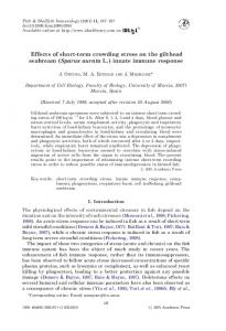
b
a Figure
(c) (d)
(e) (f)
(g) 2. Structural
impedance
formulation
The structural impedance method (SIM)“*” is a direct numerical approach based on an integral formulation. This method is suitable for analysing vehicle-bridge interactions. An attractive feature of this method lies in its ability to account for any prescribed boundary conditions, because the effects of boundaries are embedded in the influence functions. Moreover, this method is capable of solving multidimensional problems and is efficient and simpler than other numerical techniques (e.g., finite element, boundary integral equation). In the static analysis of cable-stayed bridge structures, the vehicle weight and the weight of the bridge deck are considered as forces acting on the deck. On the other hand, the dynamic analysis considers the following forces in determining the nodal displacements of and the stresses in the bridge deck: (i) the weight of the deck; (ii) the inertia forces of the deck mass (including girders); (iii) damping forces due to the deck; (iv) the vehicle-bridge deck interaction forces, including damping forces; and (v) cable forces and support reactions. In the algorithm presented here the moving mass formulation is presented as a general case; the moving force and the static solutions are obtained as special cases. The following assumptions are made: (a) The interaction forces between the tower and the cables are neglected. (b) The vehicle is modelled as a single suspension unit for simplicity. All movements of the suspension unit, except the vertical motions, are constrained. Thus each
878
Appl.
Math.
Modelling,
1996,
Vol. 20, December
1.
Vehicle-plate
model
suspension system is assumed to have only one degree of freedom. The tower is considered to be infinitely rigid and the bending effects are neglected. The effect of wind load on the superstructure of the bridge and the exposed surfaces of vehicles are neglected. Horizontal forces transmitted by the vehicle to the bridge deck due to braking are neglected. The contact between the vehicle and bridge is considered to be a point contact, and the vehicle is not modelled as a patch load. The bridge model displays linear behavior. Possible nonlinearities due to large displacements of the tower, bending moment-axial force interaction, and catenary action of cables are neglected.
The mathematical model of the structure (equivalent bridge deck and girder) consists of thin plate elements with arbitrary boundary conditions and linear springs at the intersection of cables with the bridge deck, as depicted in Figure 1. Note that T, is the force in the cable and V and H are the vertical and horizontal components of the cable forces, respectively. The following assumptions regarding the behavior of the thin plate model are made: (i) The plate material is homogeneous, linearly elastic, and orthotopic. (ii) the deflections are small compared to the thickness of the plate. (iii) The middle surface remains unrestrained during deformation, and no in-plane forces develop because of the loading. The plate element considered in developing the SIM algorithm has three degrees of freedom (DOF) at each of the four corner nodes, namely: vertical displacement, rotation about the y-axis, and rotation about the x-axis, as shown in Figure 2.
3. Moving mass formulation To account for the complete cable-stayed bridge-vehicle interaction effects, the traversing vehicle and plate are considered as a single unit and the transverse inertia
Cable-stayed
bridges
and moving
vehicles:
M. Zaman
et al.
tions to analyze vehicle-guideway interaction problems.” Alternatively, the vehicle loads can be treated as patch loads. To obtain the governing differential equation of the idealised vehicle-bridge deck system (i.e., plate), it is considered that the deflection of the deck is caused by the weight and inertia of the vehicle and the inertia of the slab itself. Considering the equilibrium of various forces acting on the system, the dynamic deflection of the deck can be expressed as
J--a,
i=l
a
h
Il
-
0
I
m(cf,
2.
Plate
model
effects of the moving The contact between structure is assumed Previous studies have
with
degrees
of freedom.
vehicle are taken into consideration. the vehicle and the idealised bridge for simplicity to be a point contact. sussessfully adopted similar idealisa-
I
Mi
I
I k
I
1
7 up
(a) Suspension
system.
da de
)
I
F
(b) Free body diagram
1
v
ci
i
@)
(4 3.
l,r)
xw(a,
4
i
Figure
d
E)Z
i---l fk ”i
17
I
l)j-pr?*+D(a,
where w(x, y, t) is the dynamic deflection of point (x, y> at time t, G(x, y, a, E) is the flexibility function that is evalutated as the deflection at a point (x, y) when a unit static load is placed at ((Y, E), D((Y, E) is the cable damping coefficient, m( a, E) is the mass per unit area of the plate, E and (Y are integration parameters, and I is the total number of suspension units. According to the D’Alembert’s principle, the total dynamic deflection (equation (1)) of a point on the plate at time I is equal to the displacement induced by the interaction force 4., inertia forces, and damping forces in the plate. The effects of cables are included in the evaluation of the influence functions. The free body diagram of the vehicle masses is shown in Figure 3 in which fki and fci represent the spring and dashpot forces, respectively.
w4 Figure
G(x,y, a, E)
0
of suspension
Appl.
system.
Math.
Modelling,
1996,
Vol. 20, December
879
Cable-stayed
bridges
and moving
vehicles:
M. Zaman
et al.
;,(a,
Using Newton’s second law of motion for the suspended masses, the following expression can be written:
fk + f,, = M,g -M&i,(t) From Figure 3 it is evident
A(x - 5, Y - ~1
(2)
E,f) =
5$W(%E, 5)
(14)
d2 d2 ~w(a,e,,)=5$w(o,c,S)+S2~w(a,E,5
that (15)
f/c,+fc,= F,
(3)
In view of equations is obtained:
(1) and (2), the following expression
Similarly, for the vehicle displacements u,(t)
F, = M,(g - iii(t)> A(x - 5,~ - 77)
ui, (16)
= Ui( 5)
(4) (17)
where A is the Dirac’s delta function, which equals zero, except at x = 5 and y = 7, which is the location of the mass, and its integral over the entire domain is equal to 1. To evaluate the relationship between the displacement of the mass (ui) and the deflection of the slab (w), the spring and the dashpot are assumed to be linear. The equations for the spring force fki and the dashpot force fCi can be written as
fk, = k,(u,(t) - w(5,1) + sj, t))
(5)
f,, = c,hqt> - ti;(5,?j+ sj, t>)
(6)
(18)
and w#)
= w(x = 5, y = 77+ si, t>
or W(5,77+Si,t)=W(5,~+Si,5>
The governing differential equation of the deck can be obtained by substituting equation (4) into equation (1):
w(x,y,
t> + // 0
a
h
m(a, E)s
X
G(x,y,
E)
a,
0
d2
l
+D(cY,
i=
The trajectory
equation
1
(7)
is given by i=1,2,3
,...,
I
(8)
Where I represents the total number of vehicles. The initial conditions for the idealised dynamic interaction problem under consideration are given by = 0
(9)
ti(x, y,O) = 0
(10)
u,(t)
(11)
= Uj( 5 1
L&(O)= 0
By representing the position time one can write
Math.
In view of equations (13) through (19), equation expressed in a convenient form as
= of the vehicle
as a pseudo
(20)
(7) can be
Modelling,
C G(x,Y,6>T+Si) i=l
x,i[
w(a, E,f) = w((Y, E, 5)
Appl.
+kiw( 5,~ + Si, 7) + Mig
(12)
3.1 Pseudo time variable
880
where (= &$/at is the speed of the first suspension unit, and 5 = d y/dt* is the acceleration of the first suspension unit. Eliminating fci and fki from equations (21, (5), and (6) and then equations (13) through (191 in equation (7) gives
I
- .$,y - 7)
Fi(5,,77,)=F(5,77+‘i)
w(x,y,O)
(19b)
)i
[
d*u,(t) -----A(x dt2
(19a)
(13)
1996,
Vol. 20,
December
g(t$ +(‘$)ui(CT)] c21)
Cable-stayed
bridges
and moving
vehicles:
M. Zaman
et al.
It may be noted that equations (20) and (21) are explicit in 5 and implicit in time. Since the dynamic response of a bridge for specified (critical) locations is usually required in the design, these equations can be solved directly by using appropriate numerical techniques, as discussed in the following section.
3.2 Discretisation
of the equations of motion
An approximate solution method is employed here by replacing the integral expression by the finite difference representation. The length and width of the slab are divided into N and M segments, respectively. The resulting expression for the equation of motion can be expressed as
G(x,y,
=
a,
E)
N+l
M+l
k=l
q=l
c c
+eig
G(x,,Y~,x~,Y~)
+
where f, and fk are functions of spacing. For the integration scheme (trapezoidal rule) chosen here, they are given by fi =fn+, = h/2, and f2 = f3 =f,, = h, where h = a/N for f,, and h = b/M for fk. In equation 22, r and / represent N + 1 and M + 1 discrete station points along the length and the width of the slab, respectively. The time variable 5 can be evaluated using a suitable time integration scheme. Newmark’s p method with constant acceleration is used here because of its unconditional stability and zero numerical damping. Equations (20) and (21) thus reduce to
Nfl
M+l
C
c q=l
k=l
(23)
G(x,,YI>+Y~)
+D(x,, ,,I(_& 1
= f:
G(~,,Y~,~>T+$)
i=l
Appl. Math.
Modelling,
1996,
Vol. 20, December
881
Cable-stayed
bridges N
+
vehicles:
M. Zaman
et al.
M
C C k=l
and moving
G(Xi,Y,,Xk,Yq)
-Zs(Aljui( [j_ 1)
q=l
+ Z2{W)hh - Zg{W’}hh - Zq{W"}/Z/T + Zro{A}j X([d.xky~q)(i$+izj-&)
(28b)
-[m(xk,yq)( $(1-i)-i2+-) il- $
)I
+D(xk3Yq)i -[mcxk,yqj(
is(l-$j)
+mx,,y,)ih
(
w'(xk,Yqt5j-1)
-i2f(f-p))
1- ;
(280
II
xW”(xx,Yq,6j-1)
(28g)
fqfk 1
(24)
(28h)
where ei = M,/k, and f, = ci/ki and j indicates that the moving vehicle is on the jth point of the deck, which implicitly shows the elapsed time. Furthermore, u’, CL”,w’, and w” represent the first and second derivatives of u and w with respect to position. Subscripts k and 4 refer to integration points, and i and e represent any point on the deck.
(28i)
+ C G(x,,y,,6,T+Si)Mtg i= 1
P8=fiih
(28j)
1-G (
N+l z1
=
)
M+l
[Gl [ml d$$ +i’$
c
c
k=l
q=l
(
i
)
3.3 Matrix arrangement of equations
(281) Equations 23 and 24 now must be solved numerically for the unknowns u;
ZsIAh
21
+z9
(26) I
(27a)
+[oli
l--$ (
(27b)
f,fk
(28n)
))
where e, =p2ui(&j_J)
(f-io)i +,DL+$))fqfk
-P,Ui(5j_l)
-Pd~:‘(&j_,) -Pc(Ahh){wIhh + P7(Ahh%v’L/,
(280)
+ Ps(Ahh%v”~~~
+ P, (28a)
882
Appl.
Math.
Modelling,
1996,
Vol. 20, December
zs = i i=l
{G,
(28~)
Cable-stayed bridges and moving vehicles: M. Zaman et al. 4. Moving force solution
(28s) z9
=
(28t)
111
When the vehicles are travelling at a relatively low speed or the vehicle mass is much smaller than the bridge mass, the moving force might represent an acceptable approximation of the moving mass solution. In such cases the effect of vehicle-bridge interaction is small as compared to bridge inertia. The formulation of the algorithm for the moving force solution is essentially the same as that for the moving mass solution, except that the inertia effect of the travelling vehicle and hence the equations of motion for the vehicles are neglected. The corresponding dynamic equations in the matrix form are given by [Z1 + Z9llWlj = {Z*{Wlt,-
i=l
+
-ZJ{W’It,-
In the above equations (Aj) is a row matrix with all zero coefficients except the jth term, which is 1; {A}j is a column matrix with all zero coefficients except the jth term, which is 1; ~~(5) is displacement of the suspension system at the jth location, and {w)~~ is a column matrix containing deck deflections for the jth location of the moving vehicle. The coefficients of the associated matrices are given below: (Aj)
I
= [O...O 1 O...O]
1 +
(32)
zia{A}j)
5. Static solution The static deflection produced by a vehicle can be obtained by neglecting the effects of deck (bridge) inertia, the inertia of the vehicle, and the effect of the suspension system. Thus the resulting equation can be expressed as
(29) w(x,y,t>=
The size of (Ai> is (2, [(N+
Z{W’l
i i=
IXM + l)]), and
G(x,y,c-,rl+S,)I;;
(33)
1
where Fi = MigA(x - 5, y - 7). The corresponding equation is of the form
matrix
[z~I{wIc,= {z~~{Ajll
6. Numerical (30)
The size of {w}, is {[(N+
lXM+
[Gl
=G(xj,y,,x,,y,)
=
G(N+ : G(N+
1,l)
results
6.1 Comparison of results
l)], 1). G(l,l,
(34)
.
No experimental results are available in the literature14,15 that would allow a direct verification of the structural impedance (SI) algorithm developed in this study. The numerical results reported by Mirghaderir3 are used to verify the numerical results obtained from the SIM algorithm CABLESIM. The bridge model used is shown in Figure 4, and the finite-element mesh considered is shown in Figure 5. Although the CABLESIM may be used for analysing the dynamic response of cable-stayed bridges subjected to traversing multi-vehicles, the results presented in this paper consider only one vehicle. G(l,l,N+l,l) . G(l,l,N+ 1,M-t 1)
;,l,l,l). l,M+ .
.
l,l,l>
G(N+l,M+l,N+l,M+l
I (31)
Appl. Math.
Modelling,
1996,
Vol. 20, December
883
Cable-stayed
bridges
and moving
vehicles:
M. Zaman
et al.
/‘i 960 In. T
3
5
7
23
96
4
In.
I_ 2400111.
Figure 4.
1
2400 in.
Bridge model used by Mirghaderi.13
In Figure 6 the moving mass deflection of the cablestayed bridge deck is compared with the results reported by Mirghaderi. I3 In the analysis, the following dimensions and material properties are used: Length of bridge = 7,200 in. Height of tower = 900 in. Modulus of elasticity of girder = 0.0278 x lo6 ksi Moment of inertia of girder = 933120 in4 Cross-sectional area of girder = 115.2 in2 Modulus of elasticity of cables = 0.0278 x lo6 ksi Cross-sectional area of cables = 86.4 in2 Mass of vehicle = 100 kip Velocity of vehicle = 125 mph Boundary conditions: simple supports at ends and at 6,000 in from the left end with a single tower located at 2400 in from the right end The dynamic deflections of the bridge at 1200 in from left end are reported in Figure 6. As evident from this figure, there is overall agreement between the results obtained from this study and those reported by Mirghaderi for various positions of the load. For distances from 1000 to 2500 inches from the left end, the deflection values are found to be quite close; however between O-1000 inches and 2000-4000 inches some significant difference in the magnitude of deflection is noticeable. This could be attributed to the differences in the idealisations adopted in both studies as discussed below:
(a) In the present plate girder, beam.
study the bridge deck is modelled as whereas Mirghaderi idealised it as a
Figure 6. Variation of moving mass deflection under the load; load moving along centerline.
method is used (b) In the present study the finite-element to calculate the influence functions, whereas Mirghaderi used a closed-form solution. (cl The observed differences between the two solutions could also be the result of approximation made by the authors for the data reported by Mirghaderi. Specifically, details of the bridge deck (i.e., the width of deck, depth of girder) are not adequately reported by Mirghaderi. He used a girder with a length of 7200 in, a cross-sectional area of 115.2 in*, and a moment of inertia of 933,120 in4. In the present study the deck has a length of 7200 in. However the width and thickness of deck (plate) and the height of girder are proportioned to obtain a combined cross-sectional area of 115.2 in2 and a moment of inertia of 933,120 in4.
6.2 Parametric study A parametric study is conducted to determine the effects of selected parameters on the dynamic response of the bridge deck. The dynamic response of the deck to a single
NdeNumber7
* 72aolE * 'r
Figure 5.
884
Finite-element
Appl.
Math.
representation
Modelling,
of bridge deck used for verification with Mirghaderi.13
1996,
Vol. 20, December
Cable-stayed
moving suspension system representing a vehicle is investigated using the structural impedance method. Different types of finite element meshes were investigated by Khanna’ to ensure a suitable finite-element representation. Since there is no significant difference in values of stresses and deflections for the different meshes considered, a 21 X 9 mesh was selected for the purpose of the parametric study, as shown in Figures 7 and 8. The following dimensions and properties of the slab and the suspension system are used: Length of the bridge = 7200 in (two towers on each side of deck) Depth of the plate girder = 60 in Height of the tower = 900 in (two towers on each side of deck) Cross-sectional area of cables = 115.2 in2 Width of bridge deck = 300 in Mass of the vehicle = 72 kip Equivalent Young’s modulus of concrete = 0.3 X 10’ psi Poisson’s ratio = 0.15 Velocity of the moving load = 60 mph
Lorolbn of Cebb
0 Figure
7.
Finite-element
representation
o-
Lrtcetbn
of 21 X 9 mesh
bridges
and moving
vehicles:
y coordinate of the load = 150 in Boundary conditions: simply supported sides and free along the longitudinal
M. Zaman
et al.
along transverse sides
The effects of variation in percentage of steel reinforcement on bridge deflections and stresses are not considered in this study. However a method for including steel reinforcement and calculating the equivalent Young’s modulus has been given by Taheri8 Figure 9 depicts the effect of girder depth on the deck response. As noted earlier, in the present study the girders are not considered as separate structural components; rather they are considered an integral part of the bridge deck. The flexural rigidity D is used to determine the effective thickness. Thus the girder depth is used to calculate the equivalent thickness of the deck-girder system. As shown in Figure 9, the maximum dynamic dimensionless deflection wD/PY2 along the bridge deck due to a load moving along the centerline of one lane decreases with the increase in the girder depth, as expected. The girder depth varies from 40 to 80 in. As was mentioned
orrora
(one tower
on either
side of deck).
~3oein
I= 1
r
Figure
8.
_-m
L
--
1 0
o-
Finite-element
Locohn
d Cobb
representation
o-
Locolbn
of 21 x 9 mesh
ortorr
(two towers
Appl.
on either
Math.
side of deck).
Modelling,
1996,
Vol. 20, December
885
Cable-stayed
bridges and moving vehicles: M. Zaman et al. -----
Midc.
I
40 in.
4000
.......... - .- .-
3’
1 .2
0
.4
.6
.8
Figure
9.
Effect
of girder along
.2
0
depth
centerline
on maximum
dynamic
deflec-
of lane.
----...‘.-....
WI. I 60 mph WI. - 70 mph “B,. I 80 mph
- .- .-
WI. I 90 mph
---
vel. I 100 mph
-.-‘-
-.02 .2
.4
.6
.8
1.0
X/L
Figure under
886
10.
Effect
of
vehicle
the load; load moving
Appl.
velocity
along
on
dynamic
deflection
centerline.
Math. Modelling,
Figure under
.14
0
8.
m
SO mph
A
.8
.6
1.0
X/L
previously, these values are used to calculate the equivalent deck-girder depth. There is a 22% increase in maximum dynamic deflection when the girder depth is increased to 50 in from 40 in. For an increase in depth to 80 in from 60 in there is an approximately 16% decrease in the maximum dynamic deflection. Figure 10 presents the dimensionless response (wD/P/‘) under the load due a single traversing vehicle moving along the centerline of one of the lanes. The velocity was varied from 60 to 100 mph, while all other parameters are kept constant as given before. The maximum value of the dynamic deflection occurs at the center of the middle span of the bridge. The magnitude of deflection increases with the increase in the velocity of the vehicle from 60 mph to 70 mph. There is a 15% increase in the magnitude of deflection. However with an increase in velocity from 70 mph to 100 mph there is a 27% decrease in the magnitude of deflection. Figure 11 shows the dimensionless normal stress response (c,P~~/D) under the load due to load moving along centerline of lane.
.io
_
-4ooo
1.0
X/L
tion; load moving
“6,,
WI..
1996, Vol. 20, December
11.
Effect
of vehicle
the load; load moving
velocity
along
on
centerline
moving
force
stress
of lane.
Like deflections, the stresses increase with the increase in velocity from 60 mph to 70 mph (23%). With a further increase in the magnitude of velocity of 100 mph the stresses decrease by 38%. Thus the variations of deflections and stresses with respect to vehicle speed are found to be nonlinear. Figure 12 presents the various arrangements of cables in use today. The effects of different types of cable arrangements were investigated in this study, and the results are summarised below. In radial and harp-type arrangments, the cables are placed at x/e= 0.1 and 0.2 on each side of tower, whereas in the star-type arrangement they are located at 0.2 on each side of tower, where /’ is the length of the bridge. The towers are placed at a distance of x/Z= 0.25 from both ends. The deflection and stress variations under the load for several arrangements of the cables are presented in a summarised form in Figures 13 and 14. The star system is found to produce the largest deflections among the three different types of cable arrangements investigated. The load is assumed to move along the centerline. The difference in values (deflection) between that obtained using the star-type arrangement and the radial-type arrangement is about 46%. The response of the bridge deck due to the change in the number of cables on each side of tower is investigated in Figure 15. The cables are placed at x/e= 0.05, 0.1, 0.15, and 0.2 on each side of the tower for the case with four cables on each side of tower. With three cables on each side of the tower, the cables are placed at x/e= 0.1, 0.15, and 0.2, respectively, on each side of tower. For two cables on each side of tower, cables are placed at x/Z’= 0.1 and 0.2, and with one cable on each side, the cables are located at 0.1. The towers are placed at x/e= 0.25 from both ends, where e is the length of the bridge. In Figures 16 and 17, four cases are analyzed with one, two, three and four cables at each side of the tower. The maximum deflection and stress values are obtained for the case in which there is only one cable on each side of the tower, as expected. There is an 84% difference in the magnitude of deflection between the case in which there is one cable on
Cable-stayed bridges and moving vehicles: M. Zaman et al. .oa
I
%: 5 !z!
.06
.02 .04
m- "WY: i
0
Ram
Arrangement
dn -.02
X/L
Effect of variation in arrangement of cables on Figure 13. dynamic deflections under the load; load moving along centerline.
..
-3wo
1
0
.2
.4
.6
.8
1.0
X/L
Effect of cable arrangements on dynamic Figure 14. under the load; load moving along centerline.
.4 ,
stress
I
I
1
Star Arrangement Figure 12. Cable arrangement either side of the bridge deck.
with
one pair of towers
on
each side of tower and the other case, when there are four cables on each side of the tower. The stresses decreased by about 66% when the number of cables was increased from one to four on each side of tower. Not much difference in the values of deflections and stresses is observed with two, three, or four cables on each side of the tower. With the increase in the number of cables from one to four the deflections reduce marginally. A comparison of moving force and moving mass deflections of a bridge deck to a 72 kips vehicle moving along the centerline of a lane is shown in Figures 18 and 19. There is not an appreciable difference in the magnitude of deflections and stresses obtained by moving mass and
-.I
I
I 0
2
A
33
.6
1.0
X/L
Effect of variation of number of cables on dynamic Figure 15. deflections under the load; load moving along centerline.
Appl.
Math.
Modelling,
1996,
Vol. 20, December
887
Cable-stayed
bridges and moving vehicles: M. Zaman et al. 5000 .‘~~~~~~~~ 1 cable each side
.“ i .
-5ooo0
.
2
- .- .- 2 cable each side : \\ --3cable each side -. -..... 4cable each side ~--i ,
.4
.6
.6
1.0
XII
Figure
17.
stress
under
0
Effect
of variation
of number
the load; load moving
2
along
of cables
.6
.4
on dynamic
centerline.
.a
1.0
X/L
Figure tions
18. under
Variation
of moving
force
the load; load moving
along
and moving
mass deflec-
centerline.
.....--.Mwing
I
Force Response
tD#b Figure on each
16.
Possible
variations
in number
of cables;
two towers
side of the deck. -3000
1......._1
0
.6
A
2
.a
1.0
XII_
Figure under
888
Appl.
Math.
Modelling,
1996,
Vol. 20, December
lg.
Variation
of moving
the load; load moving
mass and moving force stresses
along
centerline.
Cable-stayed moving force
solutions, since the vehicle weight small as compared with the bridge deck mass.
is very
Mi ki ‘i
5, Si 7. Conclusions
The primary objective of this study was to develop a numerical procedure for analysing dynamic interactions between moving vehicles and the deck of a cable-stayed bridge. A computer code, CABLESIM, was developed to evaluate the deflections of and the stresses in the deck induced by moving vehicles. The accuracy of the computer codes was verified by comparing the numerical results with the literature. Numerical results, including the effects of vehicle velocity, girder depth, and cable geometry, on the dynamic response of the bridge deck are presented. The following conclusions are arrived at from the parametric study:
9.
10.
Nomenclature
k, W
g i
mass of the moving elastic spring of the damping coefficient position of the first the distance between (i - 1)th suspension
vehicles:
M. Zaman
et al.
vehicle ith suspension system of the ith suspension unit suspension unit the ith suspension unit and the unit along the y-direction
1. Willis,
11.
length of the slab width of the slab thickness of the plate stiffness of the cable plate deflection at a point acceleration due to gravity number of the ith suspension
and moving
References
The static and dynamic responses (deflections and stress) increase in a nonlinear manner with increased vehicle velocity. The radial-type arrangement of cables minimises deflections and stresses. The structural impedance method is found to be an effective method of evaluating the dynamic response of a bridge deck due to moving vehicles. By increasing the number of cables from one cable to four, on each side of the tower, smaller deflections and stresses are obtained.
; t
bridges
12.
13
14 15.
unit
Appl.
R. Appendix: report of the commissioners appointed to inquire into the application of iron to railway structures. Stationary Office, London, 1849 Timoshenko, S. P. and Young, D. H. Vibration problems in engineering, 3rd Ed., Van Nostrand, New York, 1955 Fleming, J. F. and Ramualdi, J. P. Dynamic response of highway bridges. ASCE J. 1961, 87, pp. 31~61 Filho, F. V. Dynamic influence lines of beams and frames. J. Struct. Dill. ASCE 1966, 92, 371-386 Veletsos, A. S. and Huang, T. Analysis of dynamic response of highway bridges. ASCE J. Eng. Mech. Dir. 1970, 96, 593-608 Morris, N. F. Dynamic analysis of cable stiffened structures. J. Struct. D&ion ASCE 1974, 127~139 Morris, N. F. Analysis of cable-stiffened structures. J. Strut. Division ASCE 1976, 102, 501~514 Taheri, M. R. Dynamic response of plates to moving loads: structural impedance and finite element methods. Ph.D Dissertation, Department of Civil Engineering, Purdue University, 1987 Khanna, A. Dynamic response of cable-stayed bridges to moving vehicles using finite element and structural impedance methods. Master’s Thesis, School of Civil Engineering and Environmental Science, University of Oklahoma, 1992 Ting, E. C., Genin, J. and Ginsberg, J. H. A general algorithm for moving mass problem. J. Sound Vibration 1974, 33, 49-62 Ting, E. C., Genin, J. and Mirghaderi, R. Structural impedance transient bridge dynamics and general traffic conditions. Structural Engineering, Purdue University, CE-STR-80-23, 1980 Taheri, M. R. and Ting, E. C. Dynamic response of plate to moving loads: structural impedance method. Comput. Strut. 1989, 33,1379-1390 Mirghaderi, R. Dynamic analysis of cable-stayed bridges. Ph.D Dissertation, Department of Civil Engineering, Purdue University, 1981 Morris, N. F. The use of modal superposition in nonlinear dynamics. Comput. Strut. 1977, 7, 65-84 Zaman, M., Taheri, M. R. and Alvappillai, A. Dynamic response of thick plate on viscoelastic foundation to moving loads. Int. J. Numer. Anal. Methods Geomech. 1991, 15, 627-647
Math.
Modelling,
1996,
Vol. 20, December
889