Dynamically Variable Line-Size Cache Exploiting High On-Chip Memory Bandwidth of Merged DRAM/Logic LSIs Koji Inoue† †
Koji Kai‡
Dept. of Computer Science and Comm. Eng. Kyushu University 6–1 Kasuga-koen, Kasuga, Fukuoka 816-8580 Japan.
[email protected] Abstract
This paper proposes a novel cache architecture suitable for merged DRAM/logic LSIs, which is called “dynamically variable line-size cache (D-VLS cache)”. The D-VLS cache can optimize its line-size according to the characteristic of programs, and attempts to improve the performance by exploiting the high on-chip memory bandwidth. In our evaluation, it is observed that the performance improvement achieved by a directmapped D-VLS cache is about 27%, compared to a conventional direct-mapped cache with fixed 32-byte lines.
1
Introduction
For merged DRAM/logic LSIs with a memory hierarchy including cache memory, we can exploit high on-chip memory bandwidth by means of replacing a whole cache line at a time on cache misses [5][10][11]. This approach tends to increase the cache-line size if we attempt to improve the attainable memory bandwidth. In general, large cache lines can benefit some application as the effect of prefetching. Larger cache lines, however, might worsen the system performance if programs do not have enough spatial locality and cache misses frequently take place. This kind of cache misses (i.e., conflict misses) could be reduced by increasing the cache associativity[10][11]. But, this approach usually makes the cache access time longer. To resolve the above-mentioned dilemma, we have proposed a concept of “variable line-size cache (VLS cache)”[5]. The VLS cache can alleviate the negative effects of larger cache-line size by partitioning the large cache line into multiple small cache lines. The performance of the VLS cache depends largely on whether
Kazuaki Murakami† ‡
Institute of Systems & Information Technologies/KYUSHU 2-1-22 Momochihama, Sawara-ku, Fukuoka 814-0001 Japan.
[email protected]
or not cache replacements can be performed with adequate line-sizes. However, the paper[5] did not have discussed how to determine the adequate cache-line size. Several studies have proposed cache architectures for adjusting the cache-line size to the characteristics of programs. Coherent caches proposed in [1][2] focused on shared-memory multiprocessor systems. For uni-processor systems, cache architectures exploiting varying amount of spatial locality have been proposed in [3][6][7]. These caches need tables for recording the memory access history for evicted data from the cache, or situations of past load/store operations. This paper proposes a realistic VLS cache architecture, which is referred to as “dynamically variable line-size cache (D-VLS cache)”. The D-VLS cache changes its cache-line size at run time according to the characteristics of application programs to execute. Line-size determinator selects adequate line-sizes based on recently observed data reference behavior. Since the algorithm for determining the adequate line-sizes is very simple, the D-VLS cache has no large tables for storing the memory access history. This scheme does not require any modification of instruction set architectures. The goal of D-VLS cache is to improve the system performance of merged DRAM/logic LSIs such as PPRAM(Parallel Processing RAM)[8] or IRAM(Intelligent RAM)[9] by making good use of the high on-chip memory bandwidth. The rest of this paper is organized as follows. Section 2 describes the concept and principle of the VLS cache. Section 3 discusses the D-VLS cache architecture. Section 4 presents some simulation results and shows the performance improvements achieved by the D-VLS cache. Section 6 concludes this paper.
Cache
Reference to 2 Reference to 3
Cache
Reference to 1
VLS cache
32-byte
Reference-Subline Adjacent-Subline Reference-Sector
Cache-Sector
32 SRAM Sub-Array 0
3
SRAM Sub-Array 2
SRAM Sub-Array 3
Index 0 Index 1 Index 2
64-byte Line
Line
0 4
1
2
3
Main Memory (a) Replace with a Minmum Line
Address-Block
Transfer-Block
(Subline)
Memory-Sector
SRAM Sub-Array 1
2
2
1
2
3
Main Memory (b) Replace with a Medium Line
Cache
(Line)
0 4
0
3
5
Legend 128-byte Line
DRAM Sub-Array 0
32 36
DRAM Sub-Array 1
DRAM Sub-Array 2
DRAM Sub-Array 3
33 37
34
35
Main Memory
0
1
2
3
Main Memory (c) Replace with a Maxmum Line
data transfer occurs
no data transfer occurs
Figure 1: Terminology for VLS Caches Figure 2: Three Different Transfer-Block Sizes on Cache Replacements
2
Variable Line-Size(VLS) Cache
2.1
Terminology
In the VLS cache, an SRAM(cache) cell array and a DRAM(main memory) cell array are divided into several subarrays. Data transfer for cache replacements is performed between corresponding SRAM and DRAM subarrays. Figure 1 summarizes the definition of terms. Address-block, or subline, is a block of data associated with a single tag in the cache. Transfer-block, or line, is a block of data transferred at once between the cache and main memory. The address-blocks from every SRAM subarray, which have the same cache-index, form a cache-sector. A cache-sector and an addressblock which are being accessed during a cache lookup are called a reference-sector and a reference-subline, respectively. When a memory reference from the processor is found a cache hit, referenced data resides in the reference-subline. Otherwise, referenced data is not in the reference-subline but only in the main memory. A memory-sector is a block of data in the main-memory, and corresponds to the cache-sector. Adjacent-subline is defined as follows. • It resides in the reference-sector, but is not the reference-subline. • Its home location in the main-memory is in the same memory-sector as that of the data which is currently being referenced by the processor.
has been referenced at leastofonce since it was 2.2• ItConcept and Principle Operations fetched into the cache.
To make good use of the high on-chip memory bandwidth, the VLS cache adjusts its transfer-block size according to the characteristics of programs. When programs have rich spatial locality, the VLS cache would determine to use larger transfer-blocks, each of which consists of lots of address-blocks. Conversely, the VLS cache would determine to use smaller transfer-blocks, each of which consists of a single or a few addressblocks, and could try to avoid cache conflicts. Since the VLS cache can avoid cache conflicts without increasing the cache associativity, the access time of it (i.e., hit time) is shorter than that of conventional caches with higher associativity[5]. When a memory access takes place, the cache tag array is looked up in the same manner as normal caches, except that every SRAM subarray has its own tag memory and the lookup is performed on every tag memory. On cache hit, the hit address-block has the required data, and the memory access performs on this address-block in the same manner as normal caches. Otherwise, one or more address-blocks are replaced on cache replacement. For the example VLS cache shown in Figure 1, there are three transfer-block sizes as follows: • Minimum transfer-block size (see Figure 2 (a)). • Medium transfer-block size (see Figure 2 (b)).
• Maximum transfer-block size (see Figure 2 (c)). Processor
3
Dynamically VLS(D-VLS) Cache
Address Tag
3.1
Architecture
The performance of the VLS cache depends heavily on how well the cache replacement is performed with optimal transfer-block size. However, the amount of spatial locality may vary both within and among program executions. The D-VLS cache changes its cacheline size at run time according to the characteristics of programs. The line-size determinator for the D-VLS cache selects adequate line-sizes based on recently observed data reference behavior. Figure 3 illustrates the block diagram of a directmapped D-VLS cache with four subarrays. The address-block size is 32 bytes, and three transfer-block sizes (32 bytes, 64 bytes, and 128 bytes) are provided. Since it does not be allowed that the medium transfer-block (64-bytes line) could not be beyond 64byte boundary in the 128-byte cache-sector, the number of combinations of address-blocks to be involved in cache replacements is just seven rather than fifteen. The cache lookup for determining cache hit or miss is carried out as follows: 1. The address generated by the processor is divided into the byte offset within an address-block, subarray field designating the subarray, index field used for indexing the tag memory, and tag field. 2. Each cache subarray has its own tag memory and comparator, and it can perform the tag-memory lookup using the index and tag fields independently with each other. 3. One of the tag-comparison results is selected by the subarray field of the address, and then the cache hit or miss is determined. The D-VLS cache provides the following for optimizing the transfer-block sizes at run time: • A reference-flag bit per address-block : This flag bit is reset to 0 when the corresponding addressblock is fetched into the cache, and is set to 1 when the address-block is accessed by the processor. It is used for determining whether the corresponding address-block is an adjacent-subline. On cache lookup, if the tag of an address-block which is not the reference-subline matches the tag field of the address and if the referenceflag bit is 1, then the address-block is an adjacentsubline.
Load/Store Data
Index SA Offset
LSS-table
MUX
reference-flag
Line-Size Specifier (LSS)
Tag
Data
32Bytes for Detection of the reference-sector
D-VLS Cache
32Bytes
32Bytes
Line-Size Determinator (LSD)
32Bytes
for Detection of the adjacent-subline MUX
Hit / Miss? SA : Subarray
Main Memory
Figure 3: Block Diagram of a Direct-Mapped D-VLS Cache • A line-size specifier (LSS) per cache-sector : This specifies the transfer-block size of the corresponding cache-sector. As described in Section 2.2, each cache-sector is in one of three states: minimum, medium, and maximum transfer-block-size states. To identify these states, every LSS provides a 2-bit state information. This means that the cache replacement is performed according to the transfer-block size which is specified by the LSS corresponding to the referencesector. • Line-size determinator (LSD) : On every cache lookup, the LSD determines the state of the line-size specifier of the reference-sector. The algorithm is given in the next section.
3.2
Line-Size Determinator Algorithm
The algorithm for determining adequate transferblock sizes is very simple. This algorithm is based on not memory-access history but the current state of the reference-sector. This means that no information of evicted data from the cache need be maintained. On every cache lookup, the LSD determines the state of the LSS of the reference-sector, as follows: 1. The LSD investigates how many adjacentsublines exist in the reference-sector using all the reference-flag bits and the tag-comparison results. 2. Based on the above-mentioned investigation result and the current state of the LSS of the reference-sector, the LSD determines the next
• FIX32, FIX64, FIX128 : Conventional 16 KB directmapped caches, each of which has a fixed transferblock(line) size of 32 bytes, 64 bytes, and 128 bytes, respectively.
Other Patterns Medium Line
Reference-Sector
Initial Minimum Line Other Patterns
Maximum Line : reference-subline or adjacent-subline
Other Patterns
Figure 4: State Transition Diagram state of the LSS. The state-transition diagram is shown in Figure 4. If there are many neighboring adjacent-sublines, the reference-sector has good spatial locality. This is because the data currently being accessed by the processor and the adjacent-sublines are fetched from the same memory-sector, and these sublines have been accessed by the processor recently. In this case, the transferblock size should become larger. Thus the state depicted in Figure 4 transits from the minimum state (32-byte line) to the medium state (64-byte line) or from the medium (64-byte line) state to the maximum state (128-byte line) when the reference-subline and adjacent-sublines construct a larger line-size than the current line-size. In contrast, if the reference-sector has been accessed sparsely before the current access, there should be few adjacent-sublines in the reference-sector. This means that the reference-sector has poor spatial locality at that time. In this case, the transfer-block size should become smaller. So the state depicted in Figure 4 transits from the maximum state (128-byte line) to the medium state (64-byte line) when the reference-subline and adjacent-sublines construct equal or smaller linesize than the medium line-size (64-byte or 32-byte line). Similarly, the state transits from the medium state (64byte line) to the minimum state (32-byte line) when the reference-subline and adjacent-sublines construct minimum line-size (32-byte line)
4 4.1
Evaluations Evaluation Models
To evaluate the effectiveness of the D-VLS cache, we simulated the following conventional fixed line-size caches and D-VLS caches.
• FIX32double : Conventional 32 KB direct-mapped cache with fixed 32-byte line size. • S-VLS128-32 : 16 KB direct-mapped VLS cache having three line sizes of 32 bytes, 64 bytes, and 128 bytes. S-VLS128-32 changes its line size program by program. The adequate line-size of each program is determined based on prior simulations. • D-VLS128-32ideal : 16 KB direct-mapped D-VLS caches having three line sizes of 32 bytes, 64 bytes, and 128 bytes. It is an ideal D-VLS cache ignoring the hardware overhead. D-VLS128-32ideal provides a line-size specifier (LSS) for each memorysector rather than for each cache-sector. • D-VLS128-32LSS1, D-VLS128-32LSS8 : 16 KB realistic direct-mapped D-VLS caches having three line sizes of 32 bytes, 64 bytes, and 128 bytes. D-VLS12832LSS1 provides an LSS for each cache-sector, while D-VLS128-32LSS8 provides an LSS for eight consecutive cache-sectors.
4.2
Methodology
We used the following four benchmark sets, each of which consists of three programs from the SPEC92 and the SPEC95 benchmark suite, as follows: • mix-int1 : 072.sc, 126.gcc, and 134.perl. • mix-int2 : 124.m88ksim, 130.li, and 147.vortex. • mix-fp : 052.alvinn, 101.tomcatv, and 103.su2cor. • mix-intfp : 132.ijpeg, 099.go, and 104.Hydro2d.
The programs in each benchmark set are assumed to run in multiprogram manner on a uni processor system, and a context switch occurs per execution of one million instructions. Mix-int1 and mix-int2 contain integer programs only, and mix-fp consists of three floating-point programs. Mix-intfp is formed by two integer and one floating-point programs. We captured address traces using QPT[4] of each benchmark set for the execution of three billion instructions. Average memory-access time (AM T = HitT ime + M issRate× M issP enalty) is a popular metric to evaluate the cache performance. Miss penalty in merged DRAM/logic LSIs can be a constant time regardless of the cache-line sizes, because of the high on-chip memory bandwidth. Moreover, the hit time overhead produced by the VLS caches is trivial[5]. As a result, we have decided to use cache miss rate as the performance metrics. We measured miss rate for each benchmark set using two cache simulators written in C: one for conventional caches with fixed line-sizes and the other for D-VLS caches.
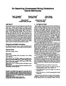
5 1.943
1.298
1.10
1.00
Normalized Miss Rate
0.90
FIX32 (base) FIX128 FIX32double S-VLS128-32 D-VLS128-32ideal D-VLS128-32LSS1 D-VLS128-32LSS8
0.80 0.70 0.60 0.50 0.40 0.30 0.20
Conclusions
In this paper, we have proposed the dynamically variable line-size cache (D-VLS cache) for merged DRAM/Logic LSIs. The line-size determinator in the D-VLS cache can detect the varying amount of spatial locality within and among programs at run time, and optimizes its cache-line size. Experimental results have shown that the realistic D-VLS caches, or D-VLS12832LSS1 and D-VLS128-32LSS8, improve the performance by about 27% and 22%, respectively, compared to a conventional cache.
0.10 0.00
Mix-int1 Mix-int2 Mix-fp Mix-intfp Average Mix-Benchmarks
Figure 5: Simulation Results
4.3
Simulation Results
References [1] Dahlgren, F., Dubois, M, and Stenstrom, P., “Fixed and Adaptive Sequential Prefetching in Shared Memory Multiprocessors,” Proc. of the 1993 International Conference on Paralled Processing, pp.56–63, Aug. 1993. [2] Dubnicki, C., and LeBlanc, T. J., “Adjustable Block Size Coherent Caches,” Proc. of the 19th Annual International Symposium on Computer Architecture, pp.170–180, May 1992.
Figure 5 shows the simulation results for all the benchmark sets and the average of them. For each benchmark set, all results are normalized to FIX32.
[3] Gonzalez, A. Aliagas, C. and Valero, M., “A Data Cache with Multiple Caching Strategies Tuned to Different Types of Locality,” Proceedings of International Conference on Supercomputing, pp.338–347, July 1995.
First, we compare the D-VLS caches (D-VLS12832LSS1 and D-VLS128-32LSS8) with the conventional caches. The fixed large lines in FIX128 worsen the system performance due to frequent evictions, while the D-VLS caches give remarkable performance improvements by means of the variable line-size. On average, FIX128 worsen the cache performance by about 30% while D-VLS128-32LSS1 and D-VLS12832LSS8 improve the performance by about 27% and 22%, respectively, compared to FIX32. These performance improvements are equal or better than that of FIX32double with two times larger cache size.
[4] Hill, M. D., Larus, J. R., Lebeck, A. R., Talluri, M., and Wood, D. A., “WARTS: Wisconsin Architectural Research Tool Set,” http://www.cs.wisc.edu/ ˜larus/warts.html, University of Wisconsin - Madison.
Next, we compare the D-VLS caches with the statically variable line-size cache (S-VLS128-32). On average, D-VLS128-32LSS1 and D-VLS128-32LSS8 are superior to S-VLS128-32. This is because S-VLS128-32 adjusts its line size among programs, while the D-VLS caches can adjust its line size both within and among programs. Finally, we compare the realistic D-VLS cache (DVLS128-32LSS1) with the ideal D-VLS cache (DVLS128-32ideal). The difference of the performance improvements given by the realistic model and the ideal model is only 5% on average. This means that the line-size determinator can select the adequate line-sizes even if it does not accurately track the amount of spatial locality of individual memory-sectors.
[5] Inoue, K., Koji, K., and Murakami, K., “High Bandwidth, Variable Line-Size Cache Architecture for Merged DRAM/Logic LSIs,” IEICE Transactions on Electronics, Vol.E81-C, No.9, pp.1438–1447, Sep. 1998. [6] Johnson, T. L., Merten, M. C, and Hwu, W. W., “Runtime Spatial Locality Detection and Optimization,” Proc. of the 30th Annual International Symposium on Microarchitecture, pp.57–64, Dec. 1997. [7] Kumar, S. and Wilkerson, C., “Exploiting Spatial Locality in Data Caches using Spatial Footprints,” Proc. of the 25th Annual International Symposium on Computer Architecture, pp.357–368, June 1998. [8] Murakami, K., Shirakawa, S., and Miyajima, H., “Parallel Processing RAM Chip with 256Mb DRAM and Quad Processors,” 1997 ISSCC Digest of Technical Papers, pp.228– 229, Feb. 1997. [9] Patterson, D., Anderson, T., Cardwell, N., Fromm, R., Keeton, K., Kozyrakis, C., Thomas, R., and Yelick, K., “Intelligent RAM (IRAM): Chips that remember and compute,” 1997 ISSCC Digest of Technical Papers, pp.224–225, Feb. 1997. [10] Saulsbury, A., Pong, F., and Nowatzyk, A., “Missing the Memory Wall: The Case for Processor/Memory Integration,” Proc. of the 23rd Annual International Symposium on Computer Architecture, pp.90–101, May 1996. [11] Wilson, K. M. and Olukotun, K., “Designing High Bandwidth On-Chip Caches,” Proc. of the 24th Annual International Symposium on Computer Architecture, pp.121–132, June 1997.