A publication of
CHEMICAL ENGINEERING TRANSACTIONS VOL. 33, 2013 Guest Editors: Enrico Zio, Piero Baraldi Copyright © 2013, AIDIC Servizi S.r.l., ISBN 978-88-95608-24-2; ISSN 1974-9791
The Italian Association of Chemical Engineering Online at: www.aidic.it/cet
DOI: 10.3303/CET1333014
Effect of Multiple Faults and Fault Severity on Gearbox Fault Detection in a Wind Turbine using Electrical Current Signals Ranjith Kumar Sreenilayam Raveendran*,a, Michael H. Azariana, Nam-Ho Kimb , Michael Pechta a
Center for Advanced Life Cycle Engineering (CALCE), University of Maryland, College Park, MD 20742, USA Department of Mechanical and Aerospace Engineering, University of Florida, Gainesville, Florida, USA
[email protected] b
Fault diagnosis of localized defects in motor bearings using electrical current signal analysis has previously been reported in the literature. An extension of this concept is the detection of faults in mechanical components influencing the operation of an induction motor, such as a gearbox connected to the motor, using electrical current. This paper presents a dynamic model-based approach to quantify the severity of upstream mechanical equipment faults on electrical current-based fault diagnosis metrics, using a wind turbine system as an example. A lumped parameter-based dynamic model was used to develop the system of equations representing the rotational motion of the drive train components in a wind turbine. This mechanical model was coupled with a dynamic model for a doubly-fed induction generator to simulate the electrical current output under faulty operating conditions. The changes in the fault diagnosis metric under different levels of severity of the fault were investigated. The influence of faults in multiple gears of the gearbox on the electrical current signals was also investigated. This method can be advantageous compared with existing approaches involving vibration analysis because it is a non-invasive and remote monitoring approach, and may not even require additional instrumentation. This approach is particularly useful for wind turbine operators as well as designers seeking to implement a low-cost condition monitoring solution for gear fault detection in a wind turbine.
1. Introduction Faults in electrical machines such as broken rotor bars, winding faults and bearing failures have been diagnosed by monitoring the electrical current consumed by the machine (El Hachemi Benbouzid, 2000). This method is referred to as motor current signature analysis (MCSA) in the literature. Induction motors are widely used in industrial and consumer applications. One application that is currently experiencing a growth surge is wind turbines, where they are used to convert the rotational energy, generated due to the influence of the wind flow on the blades, into electrical energy. The application of MCSA to wind turbines has been limited to the diagnosis of faults occurring within the generator of the wind turbine. This paper explores the possibility of the detection of faults in mechanical equipment directly connected to, but not physically part of the generator of a wind turbine. Several published studies have examined the use of MCSA for fault detection in wind turbine. Crabtree et al., (2010) identified the different frequency components in the frequency spectrum of the electrical current as well as instantaneous power for the diagnosis of unbalanced rotor windings in a wind turbine generator. A similar study was carried out by Wenxian Yang et al., (2010) on a wind turbine test rig for the diagnosis of mechanical imbalance in an induction motor using the generator output power as well as the rotation speed. Watson et al., (2010) used the instantaneous power output to detect rotor eccentricity in the generator of a wind turbine. Time-frequency analysis was used in their study and their approach was validated on a real wind turbine system. Yang et al., (2009) was able to identify frequency components Please cite this article as: Sreenilayam Raveendran R.K., Azarian M.H., Kim N.H., Pecht M.G., 2013, Effect of multiple faults and fault severity on gearbox fault detection in a wind turbine using electrical current signals, Chemical Engineering Transactions, 33, 79-84 79 DOI: 10.3303/CET1333014
related to the eccentric rotation of a gear in the electrical current spectrum based on experiments on a test rig which was not representative of an actual wind turbine system. A review of these prior studies indicates that the feasibility of detection of gearbox faults, such as a cracked gear tooth, in an actual wind turbine system using electrical current signals has not been carried out in the literature. Hence the objective of this paper is to develop a method to simulate gearbox faults in a wind turbine and to evaluate their detection using the electrical current. The challenges in the implementation of this technique are two-fold; the identification of frequency components in the frequency spectrum of the electrical current which correlate to the presence of the fault in the gearbox, and the sensitivity of detection of these faults in the frequency spectrum. Dynamic modeling has been used in this study to address the above challenges. The dynamic modeling approach used in this study to detect faults in mechanical equipment which influence the operation of a generator can be applied to any electromechanical system. A dynamic model for all the mechanical components is developed in this study and coupled with that of a generator to simulate the healthy and faulty cases.
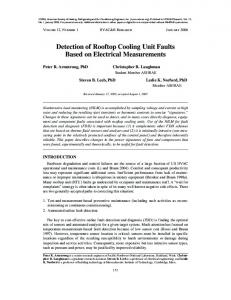
2. Dynamic model of a wind turbine system A dynamic model is an approximation of the actual system which captures the time dependent characteristics of motion of all the components in the system. A dynamic model of all the mechanical components directly interacting with the generator of a wind turbine is developed. This model is coupled with a dynamic model of the generator to simulate the electrical current under different faulty operating conditions of the wind turbine. A schematic of the wind turbine system used for simulation in this study is shown in Figure 1. This system has a planetary gear system connected to the hub and blades of the wind turbine. The total gear ratio of the gear box is 34.6.
Figure 1. Schematic of wind turbine system modeled in this study Dynamic modeling of the mechanical components is carried out in this paper using a lumped-parameter based modeling approach. Lumped-parameter systems consider that the components are discrete, with masses assumed to be rigid and concentrated at specific locations in the system. The basic elements which describe the motion of the components in dynamic modeling are the spring, mass, damper and a corresponding set for torsional elements. Torsional force balance is carried out on these lumped parameter systems to develop the equations of motion of the mechanical components. This method generates the following set of coupled differential equations of motion which represents the dynamic operation of the gearbox. It is assumed in this study that the effect of resonances due to the gear casing and other structural components do not influence the torsional rotation between the gears. ܫ ߠሷ ݇௦ଵ ሺߠ െ ߠ ሻ ݍ௦ଵ ൫ߠሶ െ ߠሶ ൯ ൌ ܶ (1)
80
మ
ଷ ቀܫ ୡ୭ୱమ ఈ ቁ ߠሷ െ ݎ ݇ ሺ͵ݎ௦ ߠ௦ െ ݎ ߠ ሻ െ ݎ ݍ ൫͵ݎ௦ ߠሶ௦ െ ݎ ߠሶ ൯ ݇௦ଵ ሺߠ െ ߠ ሻ ݍ௦ଵ ൫ߠሶ െ ߠሶ ൯ ൌ Ͳ
(2)
ܫ ߠሷ ݎ ݇ ൫ʹݎ ߠ െ ݎ௦ ߠ௦ ൯ ݎ ݍ ൫ʹݎ ߠሶ െ ݎ௦ ߠሶ௦ ൯ ൌ Ͳ ܫ௦ ߠሷ௦ ݎ௦ ݇ ൫͵ݎ௦ ߠ௦ െ ͵ݎ ߠ െ ͵ݎ ߠ ൯ ݎ௦ ݍ௦ ൫͵ݎ௦ ߠሶ௦ െ ͵ݎ ߠሶ െ ͵ݎ ߠሶ ൯ ݇௦ଶ ሺߠ௦ െ ߠଵ ሻ ݍ௦ଶ ൫ߠሶ௦ െ ߠሶଵ ൯ ൌ Ͳ ܫଵ ߠሷଵ ݎଵ ݇ଵ ሺݎଵ ߠଵ െ ݎଶ ߠଶ ሻ ݎଵ ݍଵ ൫ݎଵ ߠሶଵ െ ݎଶ ߠሶଶ ൯ െ ݇௦ଶ ሺߠ௦ െ ߠଵ ሻ െ ݍ௦ଶ ൫ߠሶ௦ െ ߠሶଵ ൯ ൌ Ͳ
(3) (4)
(5) ܫଶ ߠሷଶ ݎଶ ݇ଶ ሺݎଶ ߠଶ െ ݎଷ ߠଷ ሻ ݎଶ ݍଶ ൫ݎଶ ߠሶଶ െ ݎଷ ߠሶଷ ൯ ݎଶ ݇ଵ ሺݎଶ ߠଶ െ ݎଵ ߠଵ ሻ ݎଶ ݍଵ ൫ݎଶ ߠሶଶ െ ݎଵ ߠሶଵ ൯ ൌ Ͳ (6) ܫଷ ߠሷଷ ݎଷ ݇ଶ ሺݎଷ ߠଷ െ ݎଶ ߠଶ ሻ ݎଷ ݍଶ ൫ݎଷ ߠሶଷ െ ݎଶ ߠሶଶ ൯ ݇௦ଷ ሺߠଷ െ ߠ ሻ ݍ௦ଷ ൫ߠሶଷ െ ߠሶ ൯ ൌ Ͳ (7) ܫ ߠሷ ݇௦ଷ ሺߠ െ ߠଷ ሻ ݍ௦ଷ ൫ߠሶ െ ߠሶଷ ൯ ൌ ܶ (8) where, Subscripts: inertia hub and blades I b angular rotation sun gear s θ ሶ shaft 1 angular velocity s1 ߠ shaft 2 angular acceleration s2 ߠሷ T
torque
s3
shaft 3
k
p
planet
q r
Torsional stiffness except for subscripts rp, mb1 and mb2 where this is a linear bending stiffness damping base circle radius
r c
rotor of generator Carrier
α
pressure angle of gear tooth
rp i mb1 mb2 in el
tooth bending between ring and planet number of the gear (1, 2a, 2b or 3) tooth bending between gear 1 and 2a tooth bending between gear 2b and 3 input electrical
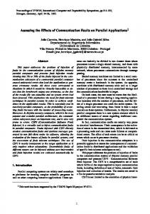
2.1 Gear mesh modeling and fault simulation Howard et al., (2001) indicated in their studies that the force is transmitted between gears in mesh by means of a double pair tooth contact and a single pair tooth contact during the mesh time. This concept is employed in this study to model the meshing between the different gears of the gearbox. Mechanical coupling between gear stages is modeled using a spring-dashpot system to represent the gear tooth interactions. The spring stiffness is modeled as a time-varying rectangular function corresponding to the single pair tooth contact and double pair tooth contact as shown in Figure 2. The dashpot damping between the gears is assumed to be a constant value. 7
Tooth Bending Stiffness (N/m)
1.3
x 10
Gear tooth with crack Undamaged gear tooth
Double pair tooth contact
1.25 1.2 1.15 1.1 1.05 1 0.95 0.9 0.85 0.025
Mesh time 0.0255
Single pair tooth contact 0.026
0.0265
Damaged gear tooth with crack
0.027
0.0275
0.028
Time (s)
Figure 2. Tooth bending stiffness variation during gear tooth mesh with and without the presence of a crack
81
Jia and Howard (2006) had reported that the stiffness of gear tooth in mesh is reduced due to the presence of a crack which was confirmed by experimental measurements as well as through finite element analysis. This concept is implemented in this model to simulate the operation of the gearbox with a crack in one of the gears. The reduction of tooth bending stiffness due to a crack is modeled only during the single pair tooth contact in this study. The variation of tooth bending stiffness with and without a crack in a gear tooth as carried out in this study is shown in Figure 2.
3. Dynamic model of induction generator The generator considered in this study is a doubly-fed induction generator (DFIG). A DFIG is essentially an induction generator where the rotor phases are also fed with a voltage to control the operation of the generator such that it always operates as a generator and not as a motor. This control is carried out by means of the turbine side controller in an actual wind turbine. In order to model time-varying inductances occurring due to the relative motion between the rotor and stator fluxes, the d-q reference frame model is used in this study (Bose, 2002). This model requires the transformation of the three phase voltages of the induction generator into the stationary d-phase and q-phase. The equivalent circuit of the DFIG in the d-q reference frame is shown in Figure 3.
A ,
A ,
,
,
Figure 3. Equivalent circuit model of a DFIG The dynamic equations of the DFIG are developed using Ohm's law and Faraday's law from the equivalent circuit model.
ܸௌ ൌ ܴ௦ ݅ௌ ܸௌௗ ൌ ܴ௦ ݅ௌௗ ܸ ൌ ܴ ݅ ܸௗ ൌ ܴ ݅ௗ
ௗఝೄ ௗ௧ ௗఝೄ ௗ௧ ௗఝೝ ௗ௧ ௗఝೝ ௗ௧
߱ ߮ௌௗ
(9)
െ ߱ ߮ௌ
(10)
ሺ߱ െ ߠሶ ሻ߮ௗ
(11)
െ ሺ߱ െ ߠሶ ሻ߮
(12)
In the above equations, subscripts S and r respectively represent the stator and rotor variables, subscripts d and q represent variables in the d-q reference frame. ϕ is the magnetic flux, R is the resistance, L is the self-inductance, M is the mutual inductance and Ȧs is the angular velocity of the AC voltage. The coupling between the mechanical model and the generator model occurs by means of the factor ߠሶ in the set of equations shown above.
4. Simulation The system of non-linear, time-varying coupled differential equations is solved using the differential algebraic system solver method. The simulation is carried out based on wind turbine parameters obtained from the literature (Todorov et al., 2009). The coupled mechanical and electrical equations are simulated for an input torque of 34654 Nm at the hub and blades, which corresponds to an angular velocity of 11 rad/s. The corresponding output torque from the gearbox is 1000 Nm.
5. Results Analysis of the electrical torque signal generated in the DFIG is carried out in this study to diagnose the presence of cracks in a gear tooth of the gearbox. The electrical torque generated in the rotor of the
82
generator due to the rotation can be calculated using coordinate transformation of the three phase current waveforms in a wind turbine application. ܶ ൌ
ଷெ ସ
൫݅ௌ ݅ௗ െ ݅ௌௗ ݅ ൯
(13)
Figure 4 shows the frequency spectrum of the electrical torque signal of the DFIG with and without a crack in gear 2b or 3 (stage 2 gears). Simulation was carried out for different levels of drop in tooth bending stiffness (kmb2). Fault case-1 has a minimum value of 0.9E7 N/m as shown in Figure 2. Fault case-2 has a minimum value of 0.8E7 N/m and hence is a worse case than fault case-1. It can be observed from Figure 4 that specific frequencies are excited in the frequency spectrum due to a fault in stage 2 gears. It can also be observed that these frequencies are excited only when there is a fault in the gear; hence the knowledge of the healthy state of the system at these frequencies is not required for determining the faulty state of the gear. Power/frequency (dB/Hz)
-40 No fault condition Fault case - 1 Fault case - 2
-50 -60 -70 -80 -90
50
100
150 200 Frequency (Hz)
250
300
Figure 4. Frequency spectrum of electrical torque signal with and without a crack in stage 2 gears A similar analysis was carried out on the electrical torque signal with a crack in stage 1 gears: 1 or 2a. The minimum value of the rectangular function of the tooth bending stiffness for the no fault condition of kmb1 is 1.8E9 N/m. The fault case-3 shown in Figure 8 has a minimum value of 1.7E9 N/m due to a crack in stage 1 gears. Analysis of the frequency spectrum of the electrical torque signal for the system operating under this faulty condition failed to detect the cracked gear tooth as shown in Figure 5.
Power/frequency (dB/Hz)
-40 No fault condition Fault case - 3
-50 -60 -70 -80 -90
50
100
150 200 Frequency (Hz)
250
300
Figure 5. Frequency spectrum of electrical torque signal with and without a crack in stage 1 gears Simulation was carried out with a simultaneous fault (fault case-3) in stage 1 and fault case-2 in stage 2 gears of the gearbox. Simulation results indicate the amplitude at the previously observed frequencies due to fault in stage 2 gears are increased comparing Figure 4 and Figure 6. This is due to the mutual coupling effect of these two faults on the angular velocity signal and the electrical torque signal.
83
-40
Power/frequency (dB/Hz)
No fault condition Fault in stage 1 and stage 2 gears -50
-60
-70
-80
-90
50
100
150 200 250 300 Frequency (Hz) Figure 6. Frequency spectrum of electrical torque signal with and without a simultaneous crack in stage 1 and stage 2 gears.
6. Conclusions A methodology for evaluating the feasibility of fault detection in upstream mechanical components connected to the generator has been developed in this study with the wind turbine generator, as an example. Simulation using a coupled dynamic model of mechanical and electrical systems in a wind turbine has confirmed that a crack in a gear tooth can be detected in the electrical torque signal of the wind turbine. Since these fault characteristic features are observed only when there is a fault in the gear, monitoring an increase in the amplitude at these frequencies is enough to identify the presence of a fault. Multiple gear faults augment the increase in the amplitude observed at these frequencies. It is also observed that the detection of faults in the electrical torque signal for faults farther away from the generator is reduced. This is due to the multiple damping effects due to the inertia of the components which reduces the intensity of the impulses in the angular velocity of the signal due to a crack, which are generated in gears farther away from the generator, from being transmitted to the generator. Analysis of the frequency spectrum using advanced frequency domain analysis techniques will be carried out in the next phase of this research to detect these effect of these faint impulses on the electrical torque signal.
References Bose, B.K., 2002. Modern power electronics and AC drives. Prentice Hall PTR. Crabtree, C.J., Djuroviü, S., Tavner, P.J., Smith, A.C., 2010. Fault frequency tracking during transient operation of wind turbine generators. Presented at the 2010 XIX International Conference on Electrical Machines (ICEM), IEEE, pp. 1–5. El Hachemi Benbouzid, M., 2000. A review of induction motors signature analysis as a medium for faults detection. Industrial Electronics, IEEE Transactions on 47, 984–993. Howard, I., Jia, S., Wang, J., 2001. The dynamic modelling of a spur gear in mesh including friction and a crack. Mechanical Systems and Signal Processing 15, 831–853. Jia, S., Howard, I., 2006. Comparison of localised spalling and crack damage from dynamic modelling of spur gear vibrations. Mechanical Systems and Signal Processing 20, 332–349. Todorov, M., Dobrev, I., Massouh, F., 2009. Analysis of torsional oscillation of the drive train in horizontalaxis wind turbine. Presented at the Advanced Electromechanical Motion Systems & Electric Drives Joint Symposium, 2009. ELECTROMOTION 2009. 8th International Symposium on, pp. 1–7. Watson, S.J., Xiang, B.J., Wenxian Yang, Tavner, P.J., Crabtree, C.J., 2010. Condition Monitoring of the Power Output of Wind Turbine Generators Using Wavelets. IEEE Transactions on Energy Conversion 25, 715–721. Wenxian Yang, Tavner, P.J., Crabtree, C.J., Wilkinson, M., 2010. Cost-Effective Condition Monitoring for Wind Turbines. Industrial Electronics, IEEE Transactions on 57, 263–271. Yang, W., Tavner, P.J., Wilkinson, M.R., 2009. Condition monitoring and fault diagnosis of a wind turbine synchronous generator drive train. IET Renewable Power Generation 3, 1 –11.
84