IEEE TRANSACTIONS ON HUMAN-MACHINE SYSTEMS, VOL. 43, NO. 2, MARCH 2013
149
Effects of Display Mode and Input Method for Handheld Control of Micro Aerial Vehicles for a Reconnaissance Mission Ming Hou, Senior Member, IEEE, Geoffrey Ho, G. Robert Arrabito, Sheila Young, and Shi Yin
Abstract—Micro aerial vehicles (MAVs) are small lightweight unmanned aerial vehicles used by dismounted soldiers for aerial reconnaissance and acquiring information for local situation awareness. MAVs require a portable handheld ground control station (GCS) that allows the operator to control and monitor the flight of the MAV. This paper investigated two methods of presenting map and sensor information, either simultaneously on one display or separately on two displays, requiring operator navigation. In addition, two input devices are evaluated: a touch screen display with a stylus versus a joystick with an OK button. The findings suggest that MAV GCSs that use touch screen inputs and simultaneous presentation of map and sensor information will result in better operator performance and reduced operator workload. Index Terms—Ground control station, handheld device, human performance, human-robot interaction, information access cost, micro aerial vehicles, touch screen, unmanned vehicles, user interface.
I. I NTRODUCTION
U
NMANNED aerial vehicles (UAVs) have been vital to military operations, including intelligence, surveillance, reconnaissance, and time-critical strikes. While media attention has primarily focused on the larger medium-altitude longendurance (MALE) UAVs (e.g., the Predator UAV), increasingly, militaries are examining the use of smaller micro aerial vehicles (MAVs) to provide dismounted soldiers with aerial reconnaissance capabilities and support in complex urban environments. MAVs are small, lightweight, and agile UAVs that are typically soldier carried in a backpack and can be either hand launched or launched with a bungee cord. Some MAVs are fixed wing, whereas others have hovering capabilities (e.g., Honeywell’s RQ-16A T-Hawk MAV). MAVs can reconnoiter “over-the-hill” or “around-the-next house,” providing situation Manuscript received March 15, 2012; revised September 6, 2012; accepted November 10, 2012. Date of current version February 12, 2013. This paper was recommended by Associate Editor J. J. Ockerman of the former IEEE Transactions on Systems, Man and Cybernetics, Part A: Systems and Humans (2011 Impact Factor: 2.123). M. Hou, G. Ho, G. R. Arrabito, and S. Young are with Defence Research and Development Canada-Toronto, ON M3K 2C9, Canada (e-mail: Ming.Hou@ drdc-rddc.gc.ca;
[email protected]; Robert.Arrabito@drdc-rddc. gc.ca;
[email protected]). S. Yin is with VisImage Systems, Inc., Markham, ON L3R 2N2, Canada (e-mail:
[email protected]). Color versions of one or more of the figures in this paper are available online at http://ieeexplore.ieee.org. Digital Object Identifier 10.1109/TSMC.2013.2239595
awareness in areas that are visually obstructed or beyond a soldier’s line of sight. Operators control and monitor the MAV through a ground control station (GCS). The GCS provides the operator with the MAV’s telemetry data, including location, flight path, airframe health, network health, and sensor information. Unlike larger UAVs, MAVs require a small portable GCS. Current MAV GCSs range from ruggedized laptops to devices similar to remote controls for toy planes; they tend to be bulky and require some time to set up each time they are used [26]. As alternatives, portable devices such as phones, personal data assistants (PDAs), and handheld game consoles can be optimal platforms for a MAV GCS because they are lightweight and small in size [7], [14], [28]. In addition, because these devices are ubiquitous in our everyday world, most operators are familiar with the different methods of user input. The main benefit of a handheld GCS is that it allows the soldier to carry the GCS in their backpack or pocket and take out the device when needed without complex setup. Despite the obvious benefits of a portable GCS, portable device designers must take into account the limitations of portable devices that can impact the perceptual, cognitive, and motor performance of the user [5], [33]. For example, smaller displays have been found to reduce estimates of flight control and path deviations [33]. In addition, the operator’s fine motor ability to control the device may be limited. The operator might be on the move, limiting his or her ability to type or provide other forms of inputs requiring fine motor coordination. A wide range of input methods have been developed for handheld devices [e.g., touch screen input with a stylus or a finger, directional pads (D-pads), and QWERTY keyboard], which must take into consideration the user’s task, the small screen real estate of handheld devices, and the mobile nature of the user. Each method of input has some advantages and disadvantages. For example, a stylus is an effective tool for pointing and selecting objects and provides a finer level of control than a mouse. However, a stylus can be misplaced, rendering the device inoperable or forcing the operator to replace the stylus with another pointing instrument [26]. In addition, unlike a mouse, it is difficult to operate buttons with the same hand using a stylus [9]. Other input methods for handheld devices include small joysticks, including D-pads, analog joysticks, and isometric joysticks. Unlike larger joysticks that require the operator to use their hand to move the joystick, these smaller joysticks only require the operator’s finger or thumb
2168-2291/$31.00 © 2013 IEEE
150
IEEE TRANSACTIONS ON HUMAN-MACHINE SYSTEMS, VOL. 43, NO. 2, MARCH 2013
to move the onscreen pointer. Research comparing isometric joysticks for handheld devices versus notebook computers for point-and-click tasks have shown that, while performance is significantly better when using a laptop on some measures (e.g., throughput and movement time), user preferences of the different devices when using isometric joysticks were not significant [31]. Other scholars have argued that the advantage of one control method over another is dependent on the spatial needs necessary for control. For example, a D-pad is limited to only eight directions of control, making it a poor choice for controlling a first-person character in a 3-D environment. A better choice would be an analog joystick that allows for movement in any direction [6]. The usefulness of various input devices for dismounted soldiers has been investigated [2], [3], [23]–[25]. Bos and Tack [2] performed an evaluation of input devices by ranking devices against the needs for a dismounted soldier. For example, infantry soldiers typically need a durable input device that requires little visual and propriceptive attention. In contrast, section commanders require input pointing devices that would allow them to draw on digital maps and interact with graphical user interfaces. While this study did not consider MAV control, their analysis suggested that an isometric joystick would best fit the needs of soldiers. However, in a subsequent study, Bos and Tack [3] found that participants preferred to have a touch screen display with a stylus. More recently, research conducted at the Army Research Laboratory has examined input devices for dismounted soldiers to control an unmanned ground vehicle (UGV) [23]–[25]. Pettitt et al. [23] compared a legacy UGV controller, a gaming controller, and a rifle-mounted controller for steering a UGV through a course and performing tasks. The legacy controller was heavier and larger than the gaming controller. The riflemounted controller had limited functionality relative to the other controllers, but it was embedded in the forward handgrip of a rifle gun. The results found no difference between the two handheld controllers, but significantly slower course completion times and greater workload for using the rifle-mounted controller. Pettitt et al. [24] also compared a game controller to a touch screen mobile phone for manually controlling a UGV. They found that the game controller produced significantly faster course completion times, fewer errors, and lower mental workload. Finally, Pettitt et al. [25] compared a game controller to a touch screen with a stylus for both manual and autonomous (using waypoints) control of a UGV. Their results found no significant differences between the two controllers in terms of maneuvering the UGV. However, participants were more efficient at performing a secondary task using the touch screen device, particularly when the UGV was controlled using waypoints. In contrast, workload favored the game controller, particularly under the manual control condition. In addition to the input method, another notable limitation of a portable GCS is the small screen size. Recent studies have investigated the use of different portable devices with varying screen sizes on operating both UAVs and UGVs and have found some mixed results [18], [19], [21], [29], [30]. For example, Oron-Gilad et al. [21] compared a 12-in tablet, a 7-in handheld device, and a head-mounted display (HMD) for operating a
UGV in an improvised explosive device detection task. No significant differences were found between the displays. However, in a subsequent intelligence-gathering task involving UAV or UGV videos, they found that the HMD resulted in lower accuracy and the highest workload. There were no significant differences in accuracy, response time, workload, or subjective measures of preference between the 12-in laptop and the 7-in handheld device, suggesting that a 7-in display might work well for a mobile operator. Minkov and Oron-Gilad [18] also conducted a study comparing participant performance while operating a UAV using a conventional 12-in laptop, a 7-in display, a PDA with a 3.5-in screen, and an HMD. They found that the PDA with the 3.5-in display produced the worst performance, the highest workload, and was least preferred by participants. Minkov and Oron-Gilad [18] suggested that the PDA did not have the graphics processing power to display the video content and that the restricted screen size limited the amount of data that could be shown on the screen. There are interface design methods that allow more information to be displayed on small screens, but they each have other drawbacks. For example, simply minimizing the information from a larger display onto a handheld device usually clutters the information on the screen. Zooming and scrolling are also methods commonly used to provide users access to information on small screens. However, zooming and scrolling should be avoided as they are time consuming and the user may lose global awareness [4], [5]. Another method to avoid display clutter is to divide information over multiple displays and allow the user to navigate between the displays. However, dividing information over multiple displays necessarily means that some information is hidden from the operator’s immediate visual field. Operators performing tasks that require information over several displays may suffer from low visual momentum, i.e., the ability to integrate information across displays [12], [35]. Displays with low visual momentum require more visual sampling, a decreased ability to find information, higher workload, and reduced problem solving [35]. Research that has examined the tradeoff between information clutter versus separating information across displays has generally concluded that the cost of cluttered displays is warranted, relative to the cost of navigation [17], [36]. For example, Kroft and Wickens [17] examined the issue of integrating information from two separate databases onto one display versus separating the information over two displays. Their data suggested that integrating the information from databases resulted in faster response times and greater accuracy, particularly for tasks requiring information from both databases. Yeh and Wickens [36] also found that, when tasks required integrating information from multiple sources, displaying all the information on one display was advantageous, despite the additional clutter. Both of these studies highlight the penalty of searching for information in terms of the increased time to find information [32] and the increased workload [34]. For any unmanned aerial system, two displays are predominantly used to convey the UAV’s information. The first is a map view, which shows the aerial map of the flight area and the UAV’s location on the map. This map may also show other information pertinent to the UAVs flight, including waypoints,
HOU et al.: EFFECTS OF DISPLAY MODE AND INPUT METHOD FOR CONTROL OF MAVs
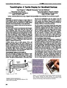
Fig. 1.
151
Viliv S5 UMPC selected as the GCS for the MAV reconnaissance task.
terrain, wind, and restricted flying areas. The second dominant display is a sensor view from the UAV. This is generally a real-time video feed from sensors aboard the UAV. Typically, while a UAV is in flight, an operator will commonly switch attention between these two displays. In a larger stationary GCS, these two displays are usually simultaneously presented on two separate computer monitors, both in view of the operator(s). However, it is unclear how to best represent these two displays on a small portable GCS. To date, we are unaware of studies that have investigated effects of screen layout or input device method for controlling a MAV. In this paper, two issues related to using a handheld device as a GCS for a MAV are examined using a simulated MAV environment. First, the input method that best supports MAV operations was investigated. Specifically, we compared inputs to the operator machine interface (OMI) of the MAV GCS using a touch screen display with a stylus versus the use of a joystick with an OK button. Second, we investigated the tradeoff between presenting the map view and the sensor view simultaneously on one screen versus placing the displays on two separate screens and having the operator navigate between the screens on a portable MAV GCS system. II. M ETHOD
Fig. 2. VNCEP environment system architecture.
of 1024 × 600 pixels. The Viliv S5 has a resistive touch screen display with a stylus but also allows for pointer controls using a joystick (located on the top left corner of the device) with an OK button (located on the top right corner of the device). The Viliv S5 was selected because the screen size met the user requirements of previously held focus groups [11], [13]. The focus groups suggested that a 7-in tablet display would be cumbersome for a dismounted soldier to carry, and a smaller device was recommended. Furthermore, the results from Minkov and Oron-Gilad [18] suggest that handheld devices should also have screens that are larger than 3.5 in. They also noted that very small devices (e.g., PDAs) often do not have the computer processing power required to display the video requirements for unmanned systems. The Viliv S5 met all of these main hardware requirements. In addition, it natively supported both a touch screen with a stylus input and a joystick with an OK button.
A. Participants
C. Simulation Environment
Forty-four volunteers (27 males, 17 females) from Defence Research and Development Canada-Toronto and the surrounding community were recruited. The age of the participants ranged from 19–55 years (M = 28.27, SD = 6.98). All participants have self-reported normal or corrected-to-normal vision and were compensated for their participation.
The virtual MAV, the virtual environment, and the GCS OMI were implemented using Adobe Flash 10.0, Lua code, and the Virtual Navigation and Collaboration Experimentation Platform (VNCEP) [22]. VNCEP uses several graphics technologies, such as OpenSceneGraph, Lua, and DirectX, to develop a customizable 3-D world. VNCEP includes a plug-in framework and a scripting interface (Lua). The plug-in framework allows for the incorporation of a data collection suite and a web server (QWIP). The Lua scripting interface allows for quick and easy adjustments to virtual objects and characters within VNCEP. VNCEP interfaced with the Viliv S5 UMPC through a wireless local network (see Fig. 2). The VNCEP served pages to the Viliv S5 UMPC. Flash files were hosted by the QWIP web server, and the Viliv S5 UMPC browser accessed the file. The Flash interface running in the web browser communicated back to the QWIP web server to request movement within the 3-D world. The QWIP server listened for these commands and streamed video back to the OMI. The simulated MAV was a fixed-wing vehicle but had vertical take-off and landing capability and could hover and station
B. Apparatus Testing took place in a quiet room. The experimental system consisted of two Lenovo desktop PCs with Intel Duo Core processors and a 17-in LCD monitor, a Viliv S5 ultra mobile personal computer (UMPC), and a Linksys WRT54GL wireless router, which connected the computers. The desktop computers ran on a Windows XP Professional 2002 platform. One desktop computer acted as the server for the virtual environment, whereas the other desktop computer provided part of the training procedure to help familiarize participants with the virtual environment. The Viliv S5 UMPC served as the handheld GCS for the MAV (see Fig. 1). It had a 4.8-in screen with a resolution
152
IEEE TRANSACTIONS ON HUMAN-MACHINE SYSTEMS, VOL. 43, NO. 2, MARCH 2013
keep in a fixed position in space. The flight characteristics of the MAV were modeled within the VNCEP. The location and heading of the MAV were determined by x, y, z, and yaw coordinates. The Lua script allowed for modification of these coordinates in order to model the MAV’s physical flight characteristics realistically. This modeling was performed in two steps. First, the OMI commanded a movement to the MAV and the VNCEP responded by moving the MAV to the commanded location. The next step allowed for interpolation of the MAV’s movement to be smoother and more realistic. The server computer also allowed the experimenter to monitor the mission, pause the mission, or stop the user control at any time. Customized software was developed for data collection. D. Input Devices The MAV GCS supported two input methods, which were used to manipulate the GCS OMI. In one condition, the GCS employed a touch screen with a stylus to enter OMI inputs (we refer to this condition as “touch screen with stylus”). Using the stylus, the operator was able to navigate the GCS screens and select and manipulate the OMI’s widgets (e.g., click buttons, rotate dials, move sliders), thus controlling the vehicle through the soft controls embedded in the OMI. The stylus was held in the participant’s dominant hand, and the GCS was held with the other hand. In the other condition, the GCS used a joystick with an OK button (we refer to this condition as the “joystick with button” condition). The joystick was found on the left side of the handheld GCS. On the right side, an OK button was present to select options (see Fig. 1). The joystick controlled the onscreen pointer (similar to a mouse cursor), which was used to select options, control onscreen widgets, and navigate between displays in the GCS OMI. Viliv officially refers to the S5 UMPC joystick as a jog dial. The jog dial behaved like a D-pad found on many gaming controllers, except that it used a mini joystick (similar to an analog joystick). The jog dial allowed for eight directions of movement, namely, up, down, left, right, and the four intermediate diagonal movements. The jog dial was a second-order control joystick. That is, to move the onscreen pointer, the participant had to move in the desired direction. To stop the onscreen pointer, the jog dial had to be released to the neutral position. Continual pressure in one direction also increased the velocity of the pointer [27]. Participants held the display with both hands and had to move the onscreen pointer with the joystick, using their left thumb. With their right thumb, they had to press the OK button to initiate an action. E. GCS Displays Two separate OMIs, representing the two main experimental conditions, were displayed on the handheld GCS. Fig. 3(a) shows what we called the “simultaneous display” condition, which displays both the map and sensor views on the same screen simultaneously. In Fig. 3(a), the map view is shown in the primary (larger) window, and the sensor view is in the secondary (smaller) window placed to the top-right side of the primary window. In this condition, the map and sensor views
Fig. 3. (a) Example of the GCS OMI using the simultaneous display condition with the map view in the primary window and the sensor view in the secondary window. In this example, the automatic mode is selected. (b) Example of the GCS OMI using the navigation display condition with the sensor view selected to be displayed. In this example, the manual mode is selected.
can be easily switched back and forth from the primary and secondary positions by clicking anywhere on the secondary window or by clicking the corresponding sensor view or map view icon located on the top-right corner of the interface. The other interface condition is referred to as the “navigation display” condition [see Fig. 3(b)]. In this condition, either the map view or the sensor view is presented in the primary window of the display. The portion of the screen where the secondary window would reside in the simultaneous display condition was replaced with white space in the navigation display condition. Similar to the simultaneous display condition, the operator could control whether the map view or the sensor view was presented in the primary window by pressing the sensor view or map view icons. A status button is located above the sensor view and map view icons. When the status button was clicked, it indicated the health of the MAV. However, it was not used in this study. The map view presented a 2-D aerial image of the virtual environment. An icon representation of a plane is placed on the map view to indicate the MAV’s current location and heading [see Fig. 3(a)]. The sensor view is a view from the MAV’s onboard camera. The sensor view was a black and white video image with an update rate of 3–4 Hz. F. Vehicle Control The participant controlled the simulated MAV with the GCS under one of two flight modes, i.e., manual or automatic. The
HOU et al.: EFFECTS OF DISPLAY MODE AND INPUT METHOD FOR CONTROL OF MAVs
two modes could be selected by using the icons on the bottomright corner of the display [see Fig. 3(a) and (b)]. In “manual mode,” the participant flew the MAV by commanding the heading and the altitude of the aircraft through the GCS OMI. In addition, the participant was able to command the plane to fly forward or to stop and hover. These were the only four commands that were available to the participant. Thus, unlike true manual flight of a UAV, wherein the operator can control the throttle and all axes of the aircraft through the joysticks and dials on the controller, the participant was unable to directly manipulate pitch, roll, or yaw or control the air speed of the MAV. In fact, our manual condition was actually still semi- automated since the MAV’s attitude and air speed were automated. However, the manual mode still required participants to engage in more active manipulation of the GCS to control the MAV’s flight through the predetermined route relative to the automated condition. The altitude and heading dials are shown in Fig. 3(a) and (b). The altitude of the MAV was represented by a meter on the OMI that indicated the current and commanded the altitude of the MAV. When in manual mode, the participant could adjust the MAV’s altitude by using the joystick or the stylus to slide the altitude set point up or down to indicate a desired altitude. To the right of the altitude indicator was the heading indicator. The heading indicator displayed the MAV’s current heading in degrees. The participant could rotate the heading of the MAV by moving the dial to the desired heading set point using the joystick or with the stylus. After the user sets the heading and the altitude, the MAV could fly forward by pressing the “Go” button [see Fig. 3(b)] with the stylus or by moving the onscreen pointer over the “Go” button with the joystick and pressing the OK button. Once the “Go” button was pressed, the MAV would fly in the direction of the set heading at a constant speed. If the user needed to turn the MAV, the heading dial could be rotated while the MAV was flying or while the MAV was hovering. The user could press the “Stop” button by clicking it with the stylus or moving the onscreen pointer with the joystick over the Stop button and pressing OK; this action would stop the MAV where it would hover in mid-air (the Stop button is not shown in Fig. 3(b), but replaces the Go button after Go has been pressed). When operating in sensor view, directional arrow buttons placed around the primary display window allowed the user to fine tune the position heading and the altitude of the MAV [see Fig. 3(b)]. A “Reset” button was available to restart the mission if the mission failed [see Fig. 3(a) and (b)]. In the manual mode, the participant was also able to zoom in and out the sensor view using the “+” and “−” magnifying glass icons [see Fig. 3(b)]. In automatic mode, the MAV was flown by creating waypoints. An automated flight route could be created by pressing the Create Route button [see Fig. 4(a)]. Waypoints could be then created by touching any area in the map (with the stylus) or by moving the onscreen pointer to any area in the map with the joystick and clicking the OK button. Any number of waypoints could be created, and the MAV would fly to each waypoint sequentially. Waypoints were presented on the OMI as small green, blue, or red crosses representing the first, intermediate, and last waypoints, respectively. On the right side of the OMI, a
153
Fig. 4. Example of the workflow used for creating a route of waypoints for the MAV on the GCS OMI. (a) Create Route button used to start a new route. (b) Example of a simple route, with a starting waypoint, an intermediate waypoint, and a terminal waypoint; and the Save Route, Save and Clear, and Undo buttons used to save and create new waypoints. (c) A completed route with the trajectory of the MAV shown and the Start Mission button, which is used to task the MAV to the route.
Save Route button allowed the participant to save the route, an Undo button allowed the participant to delete the last waypoint, and the Stop and Clear button allowed the participant to delete all of the waypoints [see Fig. 4(b)]. A Start Mission button commenced the flight of the MAV through the defined waypoint path [see Fig. 4(c)]. When in automatic mode, the altitude was preset such that the MAV would fly above the buildings and the heading was set through the waypoints. Participants were given a reconnaissance task using the MAV. In order to minimize the duration of the experiment, we asked all participants to fly the first portion of the task in automatic mode. In the latter portion of the task, where greater control of the MAV was necessary, were participants asked to fly the MAV in manual mode. The use of automatic and manual modes was constant for all participants, and the flight mode was not a variable in the experiment design. G. Reconnaissance Task The reconnaissance task required participants to fly the MAV at a constant predetermined velocity, follow a specific route, identify a specific building, enter this building through a
154
IEEE TRANSACTIONS ON HUMAN-MACHINE SYSTEMS, VOL. 43, NO. 2, MARCH 2013
From Positions 0 to 3, the participant had to set the waypoints at the marker positions on the map display and fly the MAV at a constant speed along the waypoint path in automatic mode. At Position 3, the participant had to switch and fly the MAV in manual mode. The participant was required to adjust the altitude and the heading of the MAV to fly it through a window on the target building (Position A) to access the room where the enemy character was located and then exit the room through another window [Position E in Fig. 5(a)]. To see the window of the target building and the enemy character, participants had to use the sensor display. All participants were required to do this task without any incidents such as wall collisions or flying off the map. This reconnaissance task was developed by military subject matter experts (SMEs) and verified in a separate focus group with another set of military SMEs. The SMEs developed the route and the task based on what they considered might be a typical reconnaissance mission for an infantry soldier using a MAV. In addition, the task involves typical interactions and subtasks for flying a MAV such as assigning waypoints and manually adjusting the position of the MAV. H. Experimental Design
Fig. 5. (a) Map with predefined waypoints of the route used in this paper. (b) Sample trajectory (dashed line) of the MAV’s route.
Fig. 6. Image of the enemy target that is required to be identified in the reconnaissance task.
window, and identify an enemy target character in the building. The waypoints for the predefined route are shown in Fig. 5(a), and the trajectory of the MAV is shown in Fig. 5(b). A picture of the virtual enemy target is presented in Fig. 6. Starting from Position 0 in Fig. 5(a), participants were instructed to fly through Positions 1–3 in automatic mode and then switch to manual mode to fly through Positions A–E. By having participants use both the automatic and manual modes of flight, the participants also had to focus their attention primarily on the map view in automatic mode and on the sensor view in the manual mode.
The experiment was a 2 (Display Mode: Simultaneous Display versus Navigation Display) × 2 (Input Device: Touch Screen with Stylus versus Joystick with Button) factorial within-subjects design. Five dependent measures were collected during the experimental session. First, training time was collected as a measure of ease of training. Specifically, training time referred only to the third part of the training session (see Training Session), whereby the participant had to fly the MAV using the handheld GCS and complete the mission without any wall collisions or flying off the map. Shorter training times would suggest an advantage of one display mode or input method over another. Second, time to complete the task was measured as the time from waypoint 0 to waypoint E for each trial. Third, trajectory error was collected as a measure of UAV control accuracy. Trajectory error was defined as deviations from the closest distance between waypoints. For waypoints 1–3 in Fig. 5(a), the waypoint distances were measured in two dimensions (X and Y). For waypoints A and E in Fig. 5(a), which represent the access and exit windows, respectively, the measurement was performed in three dimensions because the experiment required the MAV to fly through the windows at a specific altitude. The trajectory error for each trial is calculated as the average error over all five waypoints for the trial. Fourth, the frequency of display switches was recorded. This was the frequency that participants navigated between the map and sensor views using the GCS interface. Last, participants completed the NASA-Task Load Index (NASA-TLX) as a measure of perceived mental workload [10]. I. Procedure Participants were individually tested. Prior to the experiment, participants filled out a demographic questionnaire. The initial training portion required approximately 60 min to complete.
HOU et al.: EFFECTS OF DISPLAY MODE AND INPUT METHOD FOR CONTROL OF MAVs
155
Subsequently, the participants performed four pairs of experimental trials, in which they flew the MAV through a prespecified route (see Experimental Session). The duration of each pair of trials was approximately 15 min. Five-minute breaks were provided at scheduled intervals. The participants were debriefed following study completion. The duration of the study was approximately 3 h. J. Training Session In the training session, participants became familiar with the virtual environment, the GCS OMI, the handheld GCS, and the task. The training was divided into three parts. In the first part, participants familiarized themselves with the virtual environment by walking through the simulated world using a first-person playable character on the training PC. It involved navigating the playable character through the given waypoints and then accessing the building that the enemy target occupied. The participant had to walk the playable character through the door of the building, make its way up a staircase, and identify the enemy target. In the second part of the training, participants were trained on the GCS OMI using the training PC. The participant was introduced to both the navigation display and simultaneous display conditions and how the OMI behaved in each condition. The participant conducted the reconnaissance task with the MAV using the OMI on the PC in both the simultaneous display and navigation display conditions. Subsequently, in the third part of the training, the participants used the handheld GCS to fly the MAV to familiarize participants with the GCS, the input devices, and the interactions involved for controlling the MAV. As in the first and second parts of the training, participants conducted the reconnaissance task with the MAV but, this time, using the handheld GCS. The time to complete each mission was recorded as a dependent measure, and participants were required to continue training until they completed the mission without any wall collisions or flying the MAV off the map. Four trials of training were performed, one for each combination of independent variables. These four training trials were counterbalanced across participants to control for order effects in learning prior to the experimental trials.
Fig. 7. Marginal main effect of Input Device on training time.
Fig. 8. Significant main effect of Input Device on task completion time.
A. Training Time Training time was marginally shorter for the touch screen with stylus condition (M = 202.58 s) relative to the joystick with button (M = 229.79 s), F (1, 43) = 3.80, p = 0.06, suggesting a slight advantage for the touch screen with stylus condition. No other effects were significant (see Fig. 7). B. Time to Complete The touch screen with stylus condition (M = 138.60 s) resulted in significantly faster times to complete than the joystick with button condition (M = 165.86 s), F = (1, 43) = 76.96, p < .001 (Fig. 8). No other effects were significant.
K. Experimental Session
C. Trajectory Error
Following the training session, participants had to fly the MAV through the same route in each condition. Each unique condition was flown twice in pairs of trials, for a total of eight trials. The order of each pair of trials was counterbalanced. After completing each trial, the participant was provided with the NASA-TLX [10] as a measure of their workload in that condition.
As shown in Fig. 9, the mean trajectory error for the touch screen with stylus (M = 56 cm) was significantly greater than for the joystick with button condition (M = 50.49 cm), suggesting that, in the touch screen with stylus condition, the MAV deviated more from its optimal path, F (1, 43) = 7.34, p = 0.01. No other effects were significant. D. Display Switch Frequency
III. R ESULTS The data were submitted to a 2 (Display Mode) × 2 (Input Device) repeated measures analysis of variance for all of the dependent measures (α = 0.05) using a Geisser–Greenhouse correction for sphericity.
There were significant main effects of Input Device F (1, 43) = 12.16, p = 0.001, and Display Mode F (1, 43) = 20.12, p < 0.001, on display switch frequency. As shown in Fig. 10, the touch screen with stylus condition resulted in significantly more display switches (M = 4.28 switches) than
156
IEEE TRANSACTIONS ON HUMAN-MACHINE SYSTEMS, VOL. 43, NO. 2, MARCH 2013
Fig. 9. Significant main effect of Input Device on trajectory error.
Fig. 10. Significant interaction of Display Mode and Input Device on display switch frequency.
the joystick with button condition (M = 3.40 switches). Significantly more display switches were also observed in the navigation display condition (M = 4.83 switches) than in the simultaneous display condition (M = 2.85 switches). These main effects are further explained by a significant Display Mode by Input Device interaction, F (1, 43) = 11.99, p = 0.001. In the simultaneous display condition, the number of display switches does not differ between the touch screen with stylus condition and the joystick with button condition (M = 2.8 and M = 2.9 switches, respectively). In contrast, in the navigation display condition, display switches were more frequent, and display switches varied by input method. In the touch screen with stylus condition (M = 5.76 switches), there were more display switches than in the joystick with button condition (M = 3.92 switches). E. Mental Workload There was a significant main effect of Input Device on mental workload. As shown in Fig. 11, participants found that the joystick with button condition was more mentally demanding (M = 36.18) than the touch screen with stylus condition (M = 24.91), F (1, 43) = 38.86, p < 0.001. No other effects were significant. IV. D ISCUSSION This paper investigated two key issues related to the usability of a handheld GCS for controlling a MAV: 1) the GCS’s
Fig. 11. Significant main effect of Input Device on mental workload, as measured by NASA-TLX [10].
Display Mode and 2) the Input Device used to plan waypoints and to maneuver and command the MAV. Overall, the results indicated that the touch screen with stylus resulted in better performance. In addition, the data suggest a small benefit of using a simultaneous display. On one hand, these findings supports previous work suggesting that dismounted soldiers find touch screen devices faster and less mentally demanding [3]. On the other hand, these findings also differ from the research on portable controllers for UGVs, which generally found better performance and less workload when using a game controller over a touch screen to maneuver a UGV [23], [25]. The variation in findings highlights the complex interaction between input devices, the task, the interface, and the technologies behind the interaction [1]. In previous research on controllers for unmanned systems [23]–[25], the vehicle was a UGV, whereas this paper looked at a MAV. The task needs and the maneuverability needs of a UGV likely made the game controller a better choice over the touch screen interaction. Pettitt et al. [23] suggested that manual control for UGVs with a game controller was preferred over the more autonomous waypoint method because of the relatively short distances that UGVs travel. In addition, routes that require the UGV to perform frequent turns or to travel through narrow spaces make touching the screen to set waypoints a tedious task. Moreover, Pettitt et al. [25] suggested that participants who used the touch screen mobile phone controller complained that it was too sensitive and resulted in many driving errors and greater workload. The research on the accuracy of touch screen displays is mixed [1]. While there is general agreement that touch screens are preferred with respect to speed and user preference, there is less agreement on whether touch screen displays result in more accurate interactions [1]. While touch screens offer a direct manipulation method for pointing, the fidelity of the interaction tool (a stylus versus a finger) and the size of the target will affect the accuracy of the interaction [16]. In this paper, overall performance was better with the touch screen with stylus, but the joystick with button did outperform the touch screen on two measures: trajectory errors and display switch frequency. Concerning trajectory error, we speculate that the stylus to assign waypoints in the touch screen condition was less accurate because the tip of the stylus was broader than the tip of the pointer controlled by the joystick. This difference in the fidelity of the pointing device may have led to the
HOU et al.: EFFECTS OF DISPLAY MODE AND INPUT METHOD FOR CONTROL OF MAVs
more imprecise assignment of waypoints for the touch screen with stylus condition, and as a result, greater trajectory error. This advantage in accuracy for the joystick with button, albeit significant, did not appear to affect the participant’s general dissatisfaction with the joystick. The joystick with button interaction was more workload demanding. Participants had to move the pointer with the joystick with one hand and then press the OK button with the other hand, making this method of interaction more cumbersome. In addition, the participants may have had trouble controlling the velocity of the pointer. If participants were not cautious, they commonly reported overshooting their target, affecting the time to completion of the task. Overshooting targets is a common error found when using interaction devices such as joysticks and mice [1]. These types of control errors are also likely the reason behind our higher measures of workload. It is likely that, when participants would overshoot the target, they also performed subsequent corrective actions to obtain greater trajectory error accuracy. For display switch frequency, the data suggest that more switches occurred when using the touch screen with stylus, suggesting an advantage for the joystick with button condition. However, we believe that this conclusion is premature. The results are better explained by the significant Display Mode by Input Device interaction for display switch frequency, which showed that more display switches occurred for the touch screen with stylus only in the navigation display condition (see Fig. 10). The input methods did not differ when operating under the simultaneous display condition. Thus, at first glance, this result would suggest that the touch screen with stylus resulted in poorer performance in the navigation display condition. However, we believe that the low number of display switches in the joystick with button condition is actually attributed to the difficulty performing this task. Specifically, in the navigation display condition, participants needed to acquire information by navigating between the map and sensor views. When using the touch screen with stylus, participants were easily able to navigate by clicking on the appropriate icon; therefore, they navigated more frequently. However, navigation was more laborious with the joystick and button control. Thus, participants were hesitant or resistant to navigate and sacrificed their need for information acquisition as a result. This resistance to navigate explains why our data showed fewer display switches in the joystick with button condition relative to the touch screen with stylus condition when using a navigation display. In other words, the switching action with the joystick and button had a greater information access cost (IAC). IAC refers to the greater temporal, physical, or mental effort to access information [8]. According to the soft constraints hypothesis [8], the selection of low-level interactive routines (i.e., navigating to a separate display) to serve a higher goal (flying a MAV to a desired location) is moderated by the constraints presented by the environment. The human operator repeatedly performs a cost–benefit analysis to select a series of interactive routines that minimize cost in order to achieve the higher goal. In our case, a key constraint was the physical action of using the touch screen or the joystick and button. We posit that our participants
157
allocated a lower IAC to the touch screen interaction than the joystick and button interaction. For the joystick and button, the cost was high enough that participants frequently chose to sacrifice their need for the information or chose to rely on their memory for the information. Interestingly, research suggests that users who have to perform high IAC routines will compensate their cognitive strategies and hold more information in working memory as a result [20]. Thus, an interesting research question that arises from this paper is whether users of the joystick and button condition have a better memory of the display (relative to touch screen users) as a result of the higher IAC. Display switch frequency was also the only measure that had a significant difference between the simultaneous and navigation display conditions. The simultaneous display resulted in significantly fewer display switches, suggesting a slight benefit of using this type of a display. In this condition, both displays were always visually available. Hence, the participant had greater visual momentum [12], [35] and was able to gather information from both views by allocating visual attention to the desired view. In contrast, in the navigation display condition, participants were unable to sample the other view as frequently and were forced to navigate with their controls to update their situation awareness. This resulted in a situation where the participant had low visual momentum [12], [35], and thus, the navigation display method resulted in more display switches. This finding supports previous work that the cost of hiding information and forcing navigation is greater than the cost of cluttering a display with more information [17], [36]. The measured data also matched the subjective evaluations of the interface and control methods (i.e., workload). After the experiment, participants also freely provided their opinions of the interface and control methods. All the participants preferred the simultaneous display, and there was a strong preference for the touch screen with stylus method of control.
V. L IMITATIONS AND F UTURE D IRECTIONS The objective of this paper was to provide some guidance on how to design interfaces for handheld devices for controlling MAVs. While our study has some conclusive results, there were also some limitations to the work. As previously discussed, the Viliv S5 UMPC was selected as the platform for our GCS because it met a number of requirements, one of which was that it allowed us to compare touch screen interactions against joystick interactions through the natively built-in controls. However, the joystick was a secondorder joystick, and it has been found that the more complex the control order, the more difficult it is to control the joystick [6], [15]. Thus, our choice of joystick may have biased the results in favor of the touch screen display. Another potential limitation of our work has to do with the design of our user interface. The simultaneous display and navigation display conditions only differed with respect to whether the secondary view was present on the display. In the simultaneous display condition, the smaller secondary window presenting the map view or the sensor view was always present.
158
IEEE TRANSACTIONS ON HUMAN-MACHINE SYSTEMS, VOL. 43, NO. 2, MARCH 2013
In the navigation display condition, this secondary window was simply replaced by white space. One might argue that most designers would make appropriate use of this white space to make the primary window larger or to provide other pieces of additional information, thus adding more benefit to the navigation display condition. We do not disagree with this argument. We chose not to do this in order to maintain experimental control over our independent variable. We understand that in a real design situation, the decision to design a user interface with navigation largely depends on the tradeoff in having information appropriately shown on one window versus the expense of forcing users to navigate over multiple windows. Hence, although our study showed a preference for the simultaneous display condition, this finding should be considered in light of this argument. A final limitation of our study stems from the fact that because our GCS OMI was custom built for our study, our results may not be entirely generalizable to other handheld applications, including MAV tasks with different OMIs. As suggested by Babar [1], there is little consensus with regard to which form of interaction is best for any one device. The interaction device needs to compliment the device, the interface, the task, the technology, and the user. In our case, we maintained a simple interface layout with limited functionality so that the study findings would be generalizable to most MAV systems and other applications. Similarly, we developed a reconnaissance task that would be a representative task for an infantry soldier using a MAV. Undoubtedly, future research with similar interfaces and tasks would provide a clearer picture with regard to the optimal input method and display mode. Future research in this area should focus on a more ecologically valid study with infantry soldiers moving around an outdoor course while controlling the MAV, similar to the research performed with UGVs [23], [25]. A more realistic study would introduce new factors and constraints that are difficult to explore in an indoor simulation, including flight navigation problems (e.g., wind), technical problems (e.g., communications), environmental problems (e.g., glare), and operator issues (e.g., training, video game experience, and physical stress). This paper only examined the use of one device as a potential handheld GCS for a MAV. An initial focus group suggested that larger devices were not desirable and that smaller devices with screen sizes smaller than 3.5 in [11], [13] would lead to performance decrements [18]. In addition, small handheld devices typically do not meet the computer processing needs of displaying real-time video. As such, we did not compare our handheld GCS to a traditional laptop, a tablet PC, or other devices, as has been done in previous research [18], [19], [21], [29], [30]. These previous studies found that, while a 7-in screen produced negligible differences from laptop performance, smaller displays (3.5 in) were detrimental to performance. In our study, we used a 4.8-in screen and performed the task with little difficulty. While our participants did not comment on the screen size, it would be interesting to compare performance with other handheld devices of varying screen sizes. In particular, it would be interesting to compare a device such as the Viliv S5 with devices such as Apple’s iPod, which can display video and higher resolution displays with even on its small 3.5-in screen
and can use other novel interactions (e.g., tilting the iPod) to control the MAV. Pittman [26] designed a MAV interface using an iPod, and overall, participants performed well using an iPod to control a MAV. However, again, this iPod-based MAV GCS was not compared with other devices. The research on displays for MAVs is still immature, and a wide variety of other studies could be performed. In addition to conducting research on other interface design and handheld platform issues (i.e., screen size and input devices), MAV research could also focus on different MAV systems (e.g., navigation issues related to fixed-wing MAVs versus rotarywing MAVs, which have different velocity and flight characteristics), communications issues (e.g., control of MAVs under unreliable indoor communications), user demographics (e.g., age and training), and mission-related activities for MAVs. For example, MAVs are intended to be used for reconnaissance, intelligence gathering, and performing aerial surveys; however, given the limitations of screen size, resolution, and bandwidth on handheld devices, it remains to be seen how effective MAVs may be as tools for these types of activities. VI. C ONCLUSION The purpose of this paper was to provide guidance for handheld GCS interface design for the control of a MAV. Two issues are examined through an empirical study using a simulated MAV environment: display mode and input device method. The experimental results revealed that the display mode and the input device had significant effects on the operation of a MAV using a handheld device. The simultaneous display provided fewer display switches compared with the navigation display. The touch screen with stylus produced a quicker task completion time and a larger trajectory error than the joystick with buttons, resulting in a speed–accuracy tradeoff. The touch screen with stylus also facilitated a shorter training time than the joystick with buttons. Additionally, participants reported lower mental workload using the touch screen with stylus than using the joystick with buttons. The research findings provided guidance for OMI design of a GCS on a handheld device. For better performance, the interface should be designed with a combination of both sensor and map views. For ease of control, a touch screen with a stylus is preferable over a joystick with buttons. These findings provided empirical evidence for the development of the statement of requirement for MAV systems, but require further validations from field studies. ACKNOWLEDGMENT The authors would like to thank C. Liu for the technical editing. R EFERENCES [1] C. Babar, Beyond the Desktop: Designing and Using Interaction Devices. San Diego, CA: Academic, 1997. [2] J. C. Bos and D. W. Tack, “Review: Input device alternatives for infantry soldiers,” Defence Res. and Develop. Canada, Toronto, Canada, Contract Rep. CR 2005-026, Oct. 2005.
HOU et al.: EFFECTS OF DISPLAY MODE AND INPUT METHOD FOR CONTROL OF MAVs
[3] J. C. Bos and D. W. Tack, “Input device investigation for future dismounted soldier computer systems,” Defence Res. and Develop. Canada, Toronto, Canada, Contract Rep. CR 2005-052, May 2005. [4] “Joint command decision support 21st century technology demonstration: Human factors style guide,” Defence Res. and Develop. Canada, Toronto, Canada, Contract Rep. CR 2009-047, Mar. 2009. [5] L. Chittaro, “Distinctive aspects of mobile interaction and their implications for the design of multimodal interfaces,” J. Multimodal Interface, vol. 3, no. 3, pp. 157–165, Apr. 2010. [6] A. Cummings, “The evolution of game controllers and control schemes and their effect on games,” in Proc. 17th Annu. Univ. Southhampton Multimedia Syst. Conf., Southhampton, U.K., 2007, pp. 1–8. [7] T. W. Fong, N. Cabrol, C. Thorpe, and C. Baur, “A personal user interface for collaborative human–robot exploration,” presented at the Proc. Int. Symp. Artif. Intell., Robot., Autom. Space, Montréal, Canada, 2001. [8] W. D. Gray and W. T. Fu, “Soft constraints in interactive behavior: The case of ignoring perfect knowledge in-the-world for imperfect knowledge in-the-head,” Cogn. Sci., vol. 28, no. 3, pp. 359–382, May/Jun. 2004. [9] D. Goldberg and A. Goodisman, “Stylus user interfaces for manipulating text,” in Proc. 4th Annu. ACM SIGGRAPH Symp. UIST 91, Hilton Head, SC, 1991, pp. 127–135. [10] S. G. Hart and L. E. Staveland, “Development of NASA-TLX (Task Load Index): Results of empirical and theoretical research,” in Human Mental Workload, P. A. Hancock and N. Meshkati, Eds. Amsterdam, The Netherlands: North Holland, 1988, pp. 139–183. [11] T. M. Haylock, “A prototype user interface for the control of extremely agile micro-aerial vehicles,” presented at the Proc. Unmanned Syst. Canada, Ottawa, Canada, 2008. [12] J. G. Hollands, N. J. Pavlovic, Y. Enomoto, and H. Jiang, “Smooth rotation of 2-D and 3-D representations of terrain: An investigation into the utility of visual momentum,” Hum. Factors, vol. 50, no. 1, pp. 62–76, Feb. 2008. [13] M. Hou, J. Keillor, F. Wong, T. M. Haylock, and K. Somjee, “Development of prototype interfaces for the control of a micro-aerial vehicle,” presented at the Proc. Int. Ergonom. Assoc. 17th World Congr. Ergonom., Beijing, China, 2009. [14] H. Huttenrauch and M. Norman, “PocketCERO—Mobile interfaces for service robots,” in Proc. 3rd Int. Workshop Mobile HCI, Lille, France, 2001, pp. 1–7. [15] B. H. Kantowitz and G. C. Elvers, “Fitts’ law with an isometric controller: Effects of order of control and control-display gain,” J. Motor Behav., vol. 20, no. 1, pp. 53–66, Mar. 1988. [16] S. C. Lee and S. Zhai, “The performance of touch screen soft buttons,” in Proc. ACM Annu. Conf. Hum. Factors Comput. Syst. (CHI), Boston, MA, 2009, pp. 309–318. [17] P. Kroft and C. D. Wickens, “Displaying multi-domain graphical database information: An evaluation of scanning, clutter, display size, and user activity,” Inf. Des. J., vol. 11, no. 1, pp. 44–52, Jan. 2003. [18] Y. Minkov and T. Oron-Gilad, “Display type effects in military operational tasks using UAV video images,” in Proc. 53rd Annu. Meeting Hum. Factors Ergonom. Soc., San Antonio, TX, 2009, pp. 71–75. [19] Y. Minkov, S. Perry, and T. Oron-Gilad, “The effect of display size on performance of operational tasks with UAVs,” in Proc. 51st Annu. Meeting Hum. Factors Ergonom. Soc., 2007, pp. 1091–1095. [20] P. L. Morgan, J. Patrick, S. M. Waldron, S. L. King, and T. Patrick, “Improving memory after interruption: Exploiting soft constraints and manipulating information access cost,” J. Exp. Psychol. Appl., vol. 15, no. 4, pp. 291–306, Dec. 2009. [21] T. Oron-Gilad, E. S. Redden, and Y. Minkov, “Robotic displays for dismounted warfighters: A field study,” J. Cogn. Eng. Decision Making, vol. 5, no. 1, pp. 29–54, Mar. 2011. [22] M. Perlin, “Development of prototype interfaces for controlling an EAMAV,” Defence Res. and Develop. Canada, Toronto, Canada, Contract Rep. W8485-0-XKCF/A, 2008. [23] R. A. Pettitt, C. B. Carstens, and E. S. Redden, “Scalability of robotic controllers: An evaluation of controller options—Experiment III,” US Army Res. Lab., Aberdeen Proving Ground, MD, ARL-TR-5989, Apr. 2012. [24] R. A. Pettitt, E. S. Redden, and C. B. Carstens, “Scalability of robotic controllers: An evaluation of controller options,” US Army Res. Lab., Aberdeen Proving Ground, MD, ARL-TR-4457, May 2008. [25] R. A. Pettitt, E. S. Redden, N. Fung, C. B. Carstens, and D. Baran, “Scalability of robotic controllers: An evaluation of controller options— Experiment II,” US Army Res. Lab., Aberdeen Proving Ground, MD, ARL-TR-5776, Sep. 2011.
159
[26] D. Pittman, “Collaborative micro aerial vehicle exploration of outdoor environments,” M.S. thesis, Eng. and Comput. Sci. Dept., MIT, Cambridge, MA, 2010. [27] R. W. Proctor and T. Van Zandt, “Controls and controlling actions,” in Human Factors in Simple and Complex Systems, 2nd ed. Boca Raton, FL: CRC Press, 2008, ch. 15, pp. 397–432. [28] M. Quigley, M. A. Goodrich, and R. W. Beard, “Semi autonomous human–UAV interfaces for fixed-wing mini-UAVs,” in Proc. IEEE IROS, 2004, pp. 2457–2462. [29] E. S. Redden, R. A. Pettitt, C. B. Carston, and L. R. Elliott, “Scalability of robotic displays: Display size investigation,” Army Res. Lab.: Hum. Res. and Eng. Dir., Aberdeen Proving Ground, MD, Tech Rep. ARL-TR-4456, May 2008. [30] E. S. Redden, R. A. Pettitt, C. B. Carston, and L. R. Elliott, “Scaling robotic displays: Displays and techniques for dismounted movement with robots,” Army Res. Lab.: Hum. Res. and Eng. Dir., Aberdeen Proving Ground, MD, Tech Rep. ARL-TR-5174, Apr. 2010. [31] M. Silfverberg, I. S. MacKenzie, and T. Kauppinen, “An isometric joystick as a pointing device for handheld information terminals,” in Proc. Graph. Interface, Ottawa, Canada, Jun. 2001, pp. 119–126. [32] B. Smyth and P. Cotter, “The plight of the navigator: Solving the navigation problem for wireless portals,” in Proc. Lecture Notes Comput. Sci., P. De Bra, P. Brusilovsky, and R. Conejo, Eds., 2002, vol. 2347/2006, pp. 328–337. [33] E. M. Stelzer and C. D. Wickens, “Pilots strategically compensate for display enlargements in surveillance and flight control tasks,” Hum. Factors, vol. 48, no. 1, pp. 166–181, Mar. 2006. [34] J. Watts-Perotti and D. D. Woods, “How experienced users avoid getting lost in large display networks,” Int. J. Hum.-Comput. Interact., vol. 11, no. 4, pp. 269–299, Apr. 1999. [35] D. D. Woods, “Visual momentum: A concept to improve the cognitive coupling of person and computer,” Int. J. Man-Mach. Studies, vol. 21, no. 3, pp. 229–244, Sep. 1984. [36] M. Yeh and C. D. Wickens, “Attentional filtering in the design of electronic map displays: A comparison of color coding, intensity coding, and decluttering techniques,” Hum. Factors, vol. 43, no. 4, pp. 543–562, Winter 2001.
Ming Hou (M’05–SM’07) received the Ph.D. degree in human factors engineering from the University of Toronto, Toronto, ON, Canada, in 2002. He is currently a Defence Scientist and the Head of the Human–Technology Interaction Group, Defence Research and Development Canada-Toronto, where he is responsible for providing science-based advice to the Canadian Forces on investment in and application of advanced technologies for human–machine system requirements. His research interests include the areas of applied cognition, intelligent adaptive interface/system design, virtual/mixed reality, and e-learning. Dr. Hou is the Canadian National Leader of Human Systems Performance Technical Panel for the Air in The Technical Cooperation Program. He is a Human Factors Specialist of the NATO Flight In Non-Segregated Air Space Working Group. He is also a member of the Human Factors and Ergonomics Society and the Association for Computing Machinery. He was the Chair of the Symposium on Human Factors and Ergonomics at the 2009 IEEE Toronto International Conference-Science and Technology for Humanity. He has been the Co-Chair of the International Symposium on Mixed and Virtual Reality since 2004.
160
IEEE TRANSACTIONS ON HUMAN-MACHINE SYSTEMS, VOL. 43, NO. 2, MARCH 2013
Geoffrey Ho received the Ph.D. degree in psychology from the University of Calgary, Calgary, AB, Canada, in 2005. He is currently a Defence Scientist with the Human–Technology Interaction Group, Defence Research and Development Canada-Toronto, ON, Canada, where his role is to conduct and supervise in-house or contracted research and development in the area of human systems integration in support of the Canadian Forces. He has over 12 years of research and professional experience in the field of human factors. He has authored and coauthored over 30 of scientific publications and technical reports and has applied this knowledge to a wide array of domains, including surface transportation, technology for the older adults, medicine, process control, home and building controls, military applications, and unmanned systems. Dr. Ho has been a regular member of the Human Factor and Ergonomics Society and is currently a member of the Engineering Psychology Division of the American Psychological Association.
G. Robert Arrabito received the M.Sc. degree in computer science from the University of Western Ontario, London, ON, Canada, in 1990. He is currently a Defence Scientist with the Human–Technology Interaction Group, Defence Research and Development Canada-Toronto, where he is responsible for providing informed decisions and proposed solutions to the Canadian Forces on investment in and application of advanced interface technologies for operator machine interface requirements for land, sea, and air environments. His research interests include multimodal displays, intelligent adaptive system design, auditory alarm design, and sustained attention in monitoring tasks. Mr. Arrabito was invited to review papers for numerous prestigious journals. He actively participates in mentoring junior students in furthering their careers.
Sheila Young received the B.Sc. degree in neuroscience from the University of Toronto, Toronto, ON, Canada, in 2008. In 2009–2010, she was a Research Assistant Intern with the Human-Technology Interaction Group, Defence Research and Development Canada-Toronto, where she is currently a Polysomnographic Technician, performing diagnostic and therapeutic sleep procedures, as well as scoring of polysomnographic recordings.
Shi Yin received the Dr. Ing in engineering cybernetics from the Norwegian University of Science and Technology, Trondheim, Norway, in 1994. He is currently a Research Engineer with VisImage Systems, Inc., Markham, ON, Canada. He was a Postdoctoral Fellow with Nanyang Technological University, Singapore, in 1995 and a Researcher with the University of Toronto, Toronto, ON, in 1996. His current research interests are in the areas of computer vision, pattern recognition, human body 3-D modeling, virtual reality, and software engineering.