Effects of underwater communication constraints on the control of marine robot teams F. Arrichiello, D.N. Liu, S. Yerramalli, A. Pereira, J. Das, U. Mitra and G.S. Sukhatme Abstract— We address the effects of the aquatic communication channel constraints on the control performances of marine robot teams. The aquatic acoustic channels suffer from significant frequency and distance dependent attenuation, extensive time-varying multipath, motion-induced Doppler distortion and extreme channel latency due to the low speed of sound. Therefore, the available bandwidth is strongly limited and distance dependent. Due to all these limitations, the introduction of intravehicle exchanged information in the control loop of marine robots can degrade the overall system performance. We give an overview of the communication needs in the control of a marine robotic team. A realistic model of the aquatic communication channel is considered, and different limitations of the channel are addressed, e.g., message error rate and communication delays. An overview of the experimental test-bed that is used to study the communication characteristics of the aquatic channel is presented. Finally, we report on an extensive simulation study on the performance of a controller for a marine surface vessel which relies on an acoustic communication channel for information sensed at a distance.
control must simultaneously consider robot dynamics, actuation system features (fully/under-actuated), and proprioceptive/exteroceptive sensor information. In this paper, we focus on the impact of underwater acoustic communication on the performance of motion control schemes for marine robots. Our study is motivated by the fact that underwater acoustic channels are significantly more challenging than terrestrial radio channels due to strong attenuation that is both frequency and range-dependent, very large multipath delay spreads, potentially very large time-variation (Doppler effects) and extremely long delays due to the slow speed of sound underwater. Thus the data rates and accuracy offered by underwater acoustic communication systems are often significantly lower than what can be achieved in a terrestrial radio system.
I. I NTRODUCTION Deployment of underwater robot teams is challenging due to both issues concerning motion control as well as the development and use of a communication infrastructure. Further exacerbating the complexity of such systems is the fact that teams can be composed of both underwater robots as well as autonomous surface vessels (see e.g. Figure 1). Despite these challenges, there is strong interest in constructing such teams for a variety of applications including: e.g. mapping, exploration and monitoring of marine environments, data collection for oceanographic missions [9], autonomous navigation in formation [1] or autonomous operations in harbors; moreover, they can be used as nodes of mobile underwater sensor networks [12]. Despite strong interest in using such teams in the field, deployment of actual systems is difficult due to the inherent complexity of the aforementioned features relating to cooperative control methods, individual motion control, and underwater acoustic communication. Motion Filippo Arrichiello is with the Dipartimento di Automazione, Elettromagnetismo, Ingegneria dell’Informazione e Matematica Industriale, Universit`a degli Studi di Cassino, Via G. Di Biasio 43, 03043, Cassino (FR), Italy. Corresponding Author:
[email protected] Daniel N. Liu, Srinivas Yerramalli and Urbashi Mitra are with the Dept. of Electrical Enginering, Viterbi School of Engineering, University of Southern California, Los Angeles, CA 90089 USA Arvind de Menezes Pereira, Jnaneshwar Das and Gaurav S. Sukhatme are with the Dept. of Computer Science, Viterbi School of Engineering, University of Southern California, Los Angeles, CA 90089 USA This work was supported in part by the US National Science Foundation under grants CNS-0540420, CNS-0325875, CCR-0120778, OCE-0520324, CNS-0722073, CNS-0821750 (MRI); the US Office of Naval Research (ONR) under grant N00014-08-1-0693; a gift from the Okawa Foundation; and the University of Southern California’s Provost Office.
Fig. 1. The USC marine robot testbed composed of two AUVs (gliders) and two ASVs (boats).
There has been increasing interest in the effects of communication channels in the context of control systems, e.g. [15]. The bulk of the recent work has focused on features of terrestrial radio systems, but the models of communication channels are often quite abstract. When a control loop is closed using information received from a generic remote unit, the communication constraints can significantly degrade system performance. Several approaches have been undertaken to quantify the effects of communication channels in feedback control. In particular, the effects of delay and limited transmission bandwidth have been examined in the context of the overall system stability e.g.,[16], [3], [8], [4]. In this paper, we present a study of the effects of different underwater acoustic communication-induced control signal perturbations on a station-keeping algorithm for an autonomous surface vehicle (ASV). Our focus on stationkeeping in this paper is motivated by its inherent impor-
tance for supporting scientific payload deployment and our prior experience [10] with the system. In [10] we have described the performance of a station-keeping controller for an ASV with significant windage. We have shown that with a relatively simple (linearized) model of the vehicle dynamics we are able to keep station to within a single vehicle length in moderate wind conditions. In this paper we use the previously developed controller and task as a test case for a joint communication/control framework which we ultimately plan to use in a multi-ASV, multi-AUV setting of the sort schematically shown in Figure 1. To this end, we are currently developing an acoustic communication transceiver system for use on the ASV employed in [10]. This underwater acoustic communications testbed is essentially a “software” acoustic modem, where the transceiver sub-systems are implemented in C on a PC laptop. We have developed the necessary algorithms for the communications transceiver. In this work, we quantify various effects due to the underwater acoustic communication system. In particular, we examine: delay, the probability of lost measurements and the effects of lost bits or quantization of our measurements. The values of these effects are determined via the analysis of our end-to-end communications transceiver where key parameters have been set to match the needs of the station-keeping system. We underscore that the system of [10] employed an ASV and an off-the-shelf radio which communicated using wireless terrestrial radio systems. Herein, we use the underwater acoustic communications enabled ASV as a proxy for a purely underwater robotic systems. From our studies, we conclude that the additive effects of different noise sources related to the underwater communication channel simultaneously affect the control system performance and in some cases they strongly degrade its efficiency. At low values, their effect is filtered out by the slow motion dynamics of the ASV. This paper is organized as follows. Section II presents the experimental scenario where we will use the underwater communication channel for our research purposes. Section III highlights the key characteristics of the underwater communication channel; while Section IV introduces the experimental testbed developed for the acoustic communication link. Section V presents a simulative study on the effects of the underwater communication channel on the performances of a station keeping control for the ASV and, finally, Section VI highlights the main conclusions of the this work. II. C ONTROL AND COMMUNICATION IN MARINE
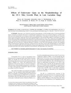
sonar or camera) are used to obtain this information through measurement. However, in the water most of these sensors have a restricted operational envelop (e.g., shallow and clear water, or limited distance due to sensor range). To overcome these constraints, an underwater communication infrastructure may be useful or, in some cases, necessary. As an example of the latter consider the case where it is desired to implement an underwater formation. The gliders can measure their positions with the onboard GPS only when they are at the surface. When underwater, they can predict their instantaneous position using their dynamic model. Without underwater communication and without an external communication infrastructure, it would be possible to coordinate the team only when the robots simultaneously emerge at the surface and communicate via radio or satellite. Consider a second scenario (a heterogeneous team composed of an ASV and an AUV). As shown in fig. 1, the ASV has constant access to GPS measurements, while the glider can access this information only when it surfaces. With an underwater communication infrastructure and with a proximity sensor to estimate the relative position, it would be possible to design a follower behavior for the AUV without frequent surfacing. In these kind of scenarios, the main issues for the single robots’ motion control are the robots’ dynamics and the communication characteristics. Since we want to mainly focus on communication aspects, in the following we will analyze a specific case study where the dynamics effects are as reduced as possible. In particular, we present a simulation study of an ASV performing a station keeping task where it does not directly sense its position. Instead, this information can be received through the underwater communication channel from a remote station that observes the vessel (see fig. 2). We analyze how the performance of the station keeping controller degrades when the position is received through an imperfect acoustic communication channel, that is, when information packets are lost or delayed.
Fig. 2. Station keeping of an ASV with position measurement received from a remote station.
ROBOTIC TEAMS
A team of marine robots composed of two underwater Slocum gliders and two Qboat Autonomous Surface Vessels (ASVs) is under development at the University of Southern California (see fig. 1). In order to perform future coordinated missions with the heterogeneous team, the single robots may need the (relative-)position information of the other robots of the team. When available, proximity sensors (e.g.,
III. ACOUSTIC COMMUNICATION CHANNEL In this section, we review key features of underwater acoustic channels and highlight the characteristics upon which we will focus for the development of our underwater acoustic communication testbed and associated algorithms. Key challenges of the underwater acoustic channel include: multipath
which induces severe inter-symbol interference (ISI), spatial and temporal variation, Doppler effects and ambient noise. The extent of these effects is dependent on local environmental conditions, the movement of the transmitter and receiver stations and the beampatterns of the acoustic transducers. Characterizing the underwater acoustic channel has been a subject of great interest [14], [11], [7]. There are fundamental differences that distinguish underwater acoustic channels from terrestrial radio frequency (RF) channels or a radiobased satellite communications channel. In summary, the key differences are a significant level of signal attenuation as a function of the carrier frequency and the transmission range, which lead to a range-dependent effective transmission bandwidth, very large latencies due to the very slow propagation of sound in water, significant inter-symbol interference (often on the order of many tens or even hundreds of symbols) and strong time-variation due to the inherent motion of the environment, regardless of the mobility of the transmitter and/or receiver. As noted above, underwater acoustic communication channels are characterized by a path loss that depends not only on the distance between the transmitter and receiver, but also on the signal/carrier frequency. The carrier frequency determines the the absorption loss due to the transfer of acoustic energy into heat in the medium. Thus the signal bandwidth at the transmitter is larger than the effective bandwidth of the received signal. Relying on extensive laboratory and field experiment data [7], [13], an empirical formula for the attenuation/path loss for a distance l(km) and frequency f(kHz) is given as A(l, f ) = A0 lk a(f )
l
(1)
where A0 is a unit normalizing constant, k is a factor depending on the geometry of propagation and a(f ) models the frequency dependence of attenuation. Note that this formula only models the attenuation due to signal propagation in the medium and does not consider the effects of other kinds of signal fading such as shadowing or attenuation due to multipath. The transmission loss due to sound absorption leads to the fundamental bandwidth limitation of the underwater acoustic channel. Large multipath delay in underwater acoustic channels is mainly due to the reflection from the surface, sea floor and other similarly sized objects in water. The speed of of sound is roughly 1500 m/s, which is orders of magnitude smaller than that of electromagnetic waves. Low propagation speed results in large delay spreads due to significant multipath in horizontal channels. Therefore, the channel impulse responses of underwater acoustic channels often has a duration of several tens of milliseconds. Moreover, in mobile underwater acoustic channels, transmitter/receiver speed and motion of reflecting surfaces will determine the coherence time of the channel. As the system is wideband, where the transmission bandwidth and the carrier frequency are comparable, the Doppler shifts cause significant time variation in the channel. Time variation due to the nonstationary medium and communicating nodes coupled with
Fig. 3.
The underwater acoustic communication testbed. Bi-Direstional Acoustic Transducer
RockfordFosgate Amplifier
External Sound Card (D/A) I/O: line-level
I/O: line-level
PC
I/O: line-level
H2O
Bi-Directional Acoustic Transducer
RENSON VP2000 Pre-Amplifier I/O: line-level/ BNC
External Sound Card (A/D)
I/O: BNC/line-level
PC
I/O: line-level
Fig. 4. Block diagram of a single link transmission in the underwater acoustic communication testbed.
large delay spreads cause significant ISI in the underwater acoustic channel. Another contrast with terrestrial RF channels is the fact that the ambient channel noise of underwater acoustic channels is colored. This coloration is determined by several factors such as: turbulence, the shipping activity in the surrounding region, the surface motion caused by wind driven waves and finally thermal noise. The constant surface motion due to wind driven waves are a significant factor contributing to the noise at the operating frequencies of interest for underwater systems ( 100 Hz - 100 kHz). Overall, the acoustic channel is noise limited at very low frequencies and attenuation limited at high frequencies. In our underwater acoustic communication testbed we are focusing on the implementation of methods to compensate for the Doppler-induced time-variation, the significant delay spreads and associated multipath as well as synchronization algorithms to cope with the long propagation delays. IV. T EST BED A. Testbed Hardware Herein we highlight the testbed system under development for the underwater acoustic communication link. The various sub-systems are reviewed; we then describe the required algorithms for the implementation of the link. Using the system parameters needed for our station-keeping algorithm, we describe the resultant performance of the various subsystems which are then translated into three abstractions of the errors induced by the use of an underwater acoustic communication link to transmit ASV position (latitude and longitude). The underwater acoustic testbed at USC is a fully configurable, real-time, single-transducer testbed. It supports carrier frequency ranges from 100 Hz to 20 kHz, with useful bandwidth up to 5 kHz. The current acoustic testbed setup, shown in Figure 3, uses a carrier frequency of 13 kHz, which
C. Synchronization
Fig. 5.
Transmission packet format.
is the resonance frequency for the acoustic transducers. The small bandwidth allows programmable implementation. Figure 4 depicts the block diagram of the underwater acoustic testbed system. The information bits are encoded, pulse shaped and up-converted in the digital domain by the computer. The generated digital samples of the transmit waveforms are then converted into analog by the external sound card. The power amplifier further amplifies the signal with a maximum gain up to 15 dB. The receiver chain provides a high performance system for the narrowband underwater acoustic testbed. The received signals are pre-amplified, then converted from analog to digital domain. All signals are generated in discrete-time complex baseband equivalent form and are directly converted to the modulated carrier frequency in digital form. The overall receiver dynamic range is greater than 80dB. Pilot symbols (for learning key features of the communications channel), demodulated data, as well as other important test information is displayed on the computer real-time. All baseband processing is done in the computer. B. Packet Structure and System Model The format of each transmitted packet [2] is shown in Figure IV-A. Each packet consists of data symbols from a 4PSK constellation. Pilot symbols used to estimate the channel impulse response are inserted at uniformly spaced locations through out the payload portion of the packet. Zero symbols are introduced on both sides of each pilot symbol to avoid interference from data symbols when estimating the channel. The number of pilots symbols in each packet depends on the packet duration as well the maximum Doppler shift for which the system is designed. A synchronization header consisting of sequences with impulse like auto-correlation functions is added at the beginning of each packet. This is used for packet detection and coarse synchronization at the receiver. The data payload of each packet corresponds to a single measurement (a latitude-longitude pair). The digital signal at the receiver, modelled as the output of a time-varying channel, given as y[n] =
L−1 X
h[n, l]x[l] + v[n]
(2)
l=0
where x[l], y[n], h[n, l] and v[n] are the transmitted symbols, received symbols, time-varying channel and the noise respectively. The parameter L, corresponds to the duration of the linear time-varying, finite impulse response filter which models the channel. The time variation of the channel is modelled using the Jakes spectrum [2].
The received samples are cross-correlated with the PN sequence at the receiver. As the PN sequence used has a impulse-like cyclic autocorrelation function, we have a peak in the correlator output whenever the channel tap is active. The square of the absolute value at the output of the correlator for the 4-PN sequences is summed and compared with a pre-determined threshold. If this value exceeds the threshold, we declare the presence of an active tap. As the underwater channel is sparse, only few active taps exist in the whole channel. The first tap to cross the threshold is declared as the start of the packet. D. Channel Estimation As the underwater channel is a fast varying channel, the use of training based channel estimation methods is preferred to the use of blind techniques. We use Pilot Symbol Assisted Modulation (PSAM) [2] training to get an estimate of the channel impulse response. Using the training procedure as described in [2], the doubly selective channel can be viewed as a combination of several flat fading channels. Assuming we use P pilot symbols, the input-output relation for channel estimation can be described as yt,l = Xt ht,l + vt,l l = 0, 1, . . . , L (3) h iT where at,l = [a[n0,l ], a[n1,l ], . . . , a[nP −1,l ] , a is either y, h or v, Xt = diag[x[n0 ], x[n1 ], . . . , x[nP −1 ]] and np,l = np + l. We use Linear Minimum Mean Square Error (LMMSE) methods to estimate the time varying channel impulse reˆ l = WH yt,l sponse. The channel estimates is given as h l where the matrix W minimizes the cost function J = arg min ||hl − WlH yt,l ||2 . W
(4)
E. Data Equalization Once the channel estimates are obtained using the pilot symbols, our signal model transforms to y[n] =
L−1 X
ˆ l]x[l] + v[n]. h[n,
n = 0, 1, . . . , N − 1
(5)
l=0
The MMSE equalizer is used to get an estimate of the data symbols. Writing the above equation in vector-matrix format and implementing the MMSE equalizer we have ˆ HH ˆ + σ 2 I)−1 H ˆ Hy ˆ = (H x
(6)
ˆ is the time-varying channel convolution matrix where H formed from the channel estimates. F. Performance Performance of the over-all communication system in terms of packet error rate (PER) with different aspects is reported in Figure 6, Figure IV-F.a and Figure IV-F.b. In Figure 6, the lower bound is simulated by assuming that synchronization and channel estimation are perfectly known to the receiver. PER performances as a function of both communication
a)
0
10
b)
0
−1
0
10 Packet Error Rate
Packet Error Rate
Packet Error Rate
10
−1
10
10
System Performance Lower bound 10
Fig. 6.
15 SNR (dB)
0.5
20
25
Packet error rate vs. SNR.
distance and wind speed are shown in Figure IV-F.a and Figure IV-F.b . These simulated PER plots provide insightful information of how different noise sources of the imperfect underwater acoustic communication link can potentially degrade the performance of a control technique for a marine surface vessels. The Signal to Noise Ratio (SNR) and the packet length determine the Packet Error Rate (PER) of the communication system. The PER is roughly a linear function of the number of symbols in the packet. For a fixed signal power, the attenuation (and the available bandwidth for data transmission) increases as the distance increases, reducing the SNR at the receiver and increasing the PER. Changes in wind speed heavily impact the noise at the receiver resulting in considerable decrease in SNR. This again would translate to a larger PER. Channel estimation and synchronization errors are also a major cause for errors in packets. The primary degradation in PER is due to imperfect channel estimation. The effect of synchronization errors is very minimal and most of the errors in packets are due to channel estimation. In addition, use of long packets increases the delay which degrades controller performance. Using a very short packet length increases the amount of overhead required to transmit data. Thus, there is a tradeoff between the packet length and data rate.
1
1.5 2 distance (km)
2.5
3
−1
10
0
2
4 6 windspeed (m/s)
8
10
Fig. 7. a) Packet error rate vs. distance; b)Packet error rate vs. windspeed
station keeping control algorithm presented in [10]. The main concepts of the vessel dynamics and the controller are given below, while further details can be found in [10]. A. Dynamic model For the QBoat marine ASV, the following well-known 3 DOF nonlinear maneuvering model [5] has been considered: η˙ Mν˙ + Dν + g(η)
= R(ψ) ν
(7)
= τ + RT(ψ) w,
(8)
T
where η = [n e ψ] is the position and attitude vector in T the North-East-Down (NED) reference frame; ν = [u v r] is the linear and angular velocity vector in the Body-fixed (BODY) reference frame; R(ψ) ∈ SO(3) is the rotation matrix from NED M is the vessel inertia matrix to BODY; 2 0 0 62.3 Ns m 2 chosen as M = 0 62.3 Ns 3.15Ns2 ; D is the m2 0 3.15 Ns 4.6Ns2 m sum of Coriolis and hydrodynamic damping matrix chosen 11.34 Ns 0 0 m as D = −12.13Ns ; τ is sum 0 13.96 Ns m 0 −0.49 Ns 3.19Ns m of the vessel propulsion force and torque plus the force due to the hydrodynamics of the hull; w is the vector of the environmental forces (wind, currents, etc.) acting on the vessel in the NED reference system.
TABLE I S YSTEM PARAMETERS Parameter Center Frequency Bandwidth (B) Symbol Time (T) Data (4-PSK const.) Pilots (including zeros) Payload Length (N) Sync. Header Max Delay Spread Max Doppler Spread Fdmax
Value 13 KHz 1 KHz 1 ms 118 symbols 123 symbols 241 symbols 4 x (31 M-seqeunce) 20 ms 2 Hz
V. C ASE S TUDY: S TATION KEEPING CONTROL WITH IMPERFECT COMMUNICATION
Consider the scenario introduced in Section II (see fig. 2), in this section we present a simulation study of the effect of a realistic underwater channel on the performances of a
B. Control Design Philosophy Given its actuation system (two parallels thrusters oriented in the forward direction, and a single rudder), the ASV is underactuated since it is incapable of producing a transverse thrust without the application of yaw and surge forces. Moreover, given its geometry, the vessel has a fairly large wind-profile (and a relatively low profile in the water) and it tends to drift fairly easily under the influence of wind. With the simplifying assumption that the direction of the current is varying very slowly and that on average the wind and current are aligned, a controller was designed in [10] to drive the vessel to a desired target position and to align with the direction of the wind when the vessel is close to the target position. The controller has been designed so as the thruster commands are computed from the combination of a heading
autopilot and a surge controller (see fig. 8 when the switch is on the GPS). The thruster commands are generated as: T hrlef t = δcomm + δdif f T hrright = δcomm − δdif f
(9) (10)
where δcomm is the output of the surge controller and δdif f is the output of the heading autopilot. The reference command to the heading autopilot and to the surge controller are computed by a command combination logic technique on the basis of the positioning error. In particular, when the vessel is far from desired position, a Line Of Sight (LOS) approach [6] is used to compute the desired heading angle and the desired surge velocity to move the vessel towards the target direction. When the positioning error is low, the desired heading is in the disturbance direction (wind/current), and the thrust in the surge direction is provided via a PD-controller of the positioning error aided by a wind-feedforward force so as to cancel out the effect of the wind force. The smooth change from one control logic to the other is regulated by a weighting function of the positioning error. Further details can be found in [10].
5 mean positioning error [m]
Fig. 8. Position control system with global positioning received from the onboard GPS or from a remote unit.
1) Effect of Packet Error Rate: Based on Figure IVF, we see that the packet error rate, which corresponds to the rate at which we lose GPS measurements as our current system transmits one measurement per packet , is dependent on the transmission range: as the range increases, the packet error rate also increases. To capture these effects, we have simulated the effects of packet loss on the mean positioning error for the station keeping controller. We consider error rates on the order of 0 (no errors) to 0.95 which roughly corresponds to a large transmission distance, on the order of 3km at a transmission SNR of 15 dB. From Figure 9 we see that the mean positioning error is not significantly affected by packet loss until this loss becomes large, on the order of 0.7. This error rate roughly corresponds to a transmission distance of 2km. However, after this point, the mean positioning error increases rapidly as a function of the error rate. We explain this behavior by noting that the communication bandwidth is high relative to the dynamics of the vessel, thus the original transmission rate of ten measurements per second is more than ample for the station-keeping controller and it is only until the effective communication rate decreases to be close to that of the vessel dynamics that we experience strong performance loss.
4 3 2 1 0
0
0.2
0.4 0.6 error rate
0.8
1
Fig. 9. Mean value and standard deviation of the positioning error for different error rate values with sample time t = .1s
C. Simulations with imperfect communication channel In the scenario shown in Figure 2, the global position information is received by the ASV from a remote unit via transmission over an underwater acoustic communication channel. In our control model, it results in moving the switch for the station keeping control of figure 8 to the Global Positioning estimated by the remote unit, where the communication suffers from the effects of the underwater communication channel. Following the considerations of Sections III-IV, we consider the following key impairments due to transmission over the underwater acoustic channel: packet error rate, transmission delay and differing quantization rates which lead to the loss of precision in the GPS measurements. We vary the level of these various losses consistent with the previous discussions and assess the resulting performance loss with regard to station-keeping. We initially begin with single sources of error and then investigate what happens when there are multiple concurrent sources of error.
2) Effect of Communication Delay: The communication delay is a function of both the packet length and the distance from the remote unit (transmission range). In examining Table 1, we see that our packet length is on the order of 300 bits (also observe that a significant part of the packet is devoted to pilot symbols, i.e. known symbols used to learn communication channel parameters), thus the delay due to the packet length is on the order of 300-400 ms. The additional propagation delay can be on the order of ∼ 2 s when the distance from the signal source reaches the order of 3 km. These values are consistent with the underwater communication performance estimated with the experimental test-bed previously described. Figure 10 shows the mean values of the station keeping positioning error at different values of the communication delay. We see that in contrast to sensitivity to error rate, delay degrades performance almost linearly. Figures 11-12, show the paths of the vessel during two missions of 1000s each. In the first mission, we examine
5
[m]
the vessel in the absence of any delay and in the second case, we have a total communication delay of 3 s. Both Figures clearly depict the fact that in neither case do we achieve asymptotic stability for the controller. This is due both to the underactuated actuation system and the control law definition. However, while Figure 11 shows an oscillation in a small range around the desired position (± 12 m) , Figure 12 shows that, with the added communication delay, the control yields limit cycles around the desire target position; in this case, however, we are in error of the desired location on the order of ±3m. This represents a much larger error than in the previous no delay case.
0
−5 −5
0 [m]
5
Fig. 12. Plot of the vessel path during a 1000s mission with a communication delay of 3s.
5
6
4 3 2 1 0
0
1
2 3 delay [s]
4
5
mean positioning error [m]
mean positioning error [m]
6
5 4 3 Delay 2 1 0
Fig. 10. Mean values and standard deviations of the positioning error for different delay values.
0
0.2
0.4 0.6 error rate
0.8
1
Fig. 13. Mean value of the positioning error for different error rate values for delay values of 0s , .3s , .6s , .9s , 1.2s , 2s 1
[m]
0.5
0
−0.5
−1 −1
−0.5
0 [m]
0.5
1
Fig. 11. Plot of the vessel path during a 1000s mission with a communication delay of 0s.
3) Joint Effects of Packet Error and Delay: In realistic systems, both the error rate and the transmission delay simultaneously affect controller performance. Thus, several simulations have been performed with these two sources of noise simultaneously active. Figure 13 shows the mean values of the positioning error at different error rates for different communication delay values. The joint effect is much more detrimental to the controller performance. We see that even modest packet error rates coupled with modest delays leads to much larger mean positioning errors. Furthermore, the presence of the delay shifts the transition point for when increases in the error rate cause an “exponential” increase in the positioning error.
4) Effect of Transmission Bandwidth: As noted in Section IV, we observed that a unique feature of the underwater acoustic channel is the fact that effective transmission bandwidth is range dependent. Thus, the longer the transmission distance, the lower data rate we can support over the link. A solution to increase the communication frequency at high distance from the transmitter is to reduce the message dimension. Several simulations have been performed reducing the message dimension gradually dropping an increasing number of bits from the measurement information. This results in introducing a growing quantization in the measurement acquisition. Figure 14 shows the plot of the mean values of the positioning error as bits are discarded (least to most significant) from the measurement information. The least significant bit of the full measurement has a resolution of 1 mm. 5) Effect of wind: Since the current degrades the communication capabilities and the controller performance, simulations have been performed gradually increasing the wind speed. Figure 15 shows the plot of the mean values of the positioning error for increasing values of the wind speed. Moreover, since the current can reduce the communication power signal and increase the error rate, Figure 16 shows the plots of the mean values of the positioning error for an increasing value of the wind speed for different values of the error rate.
mean positioning error [m]
3 2.5 2 1.5 1 0.5 0
Fig. 14.
0
2
4
6 lost bits
8
10
12
Mean value of the positioning error for values of bit lost.
mean positioning error [m]
2.5 2
R EFERENCES
1.5 1 0.5 0
0
2
4 6 wind speed [m/s]
8
10
Fig. 15. Mean value of the positioning error for different values of the wind speed.
VI. C ONCLUSION The underwater channel represents a challenging issue both from a communication point of view and for control purposes. In this paper we have performed a study on the effects of the underwater communication channel on the performance of ASV control. The aim of the paper is to present a preliminary study of the effect of a real communication channel on the control performance of a single robot that will be useful for future applications on ASV/AUV teams. Thus, after the analysis of the underwater communication channel characteristics and after the description of an experimental test-bed, a simulation study on the performance degradation
mean positioning error [m]
2
1.5 Error rate 1
0.5
0
of a station keeping algorithm has been presented. This study permits us to extrapolate a basic performance envelope for the behavior of the control system given a realistic acoustic channel over which senses data are being received for use within the control loop. From our studies, we can conclude that the control performances can be significantly affected by different noises related to the underwater communication channel. The different sources of noise, that in extreme communication conditions can simultaneously take effect, can strongly degrade the efficiency of the control system. However, when their values are low, their effect is filtered out by the slow motion dynamics of the ASV. As a consequence, their effects have to be properly taken into consideration when using the complete range covered by the acoustic communication channel.
0
2
4 6 wind speed [m/s]
8
Fig. 16. Mean value of the positioning errors for different values of the wind speed with different error rate values (0, .5, .7, .8).
[1] F. Arrichiello, S. Chiaverini, and T.I. Fossen. Formation control of marine surface vessels using the Null-Space-based Behavioral control. In Group Coordination and Cooperative Control, K.Y. Pettersen, T. Gravdahl, and H. Nijmeijer (Eds.), Springer-Verlag’s Lecture Notes in Control and Information Systems series, pages 1–19. May 2006. [2] Imad Barhumi, Geert Leus, and Marc Moonen. Time-varying fir equalization for doubly selective channels. IEEE Transactions on Wireless Communications, 4(1):202–214, 2005. [3] JH Braslavsky, RH Middleton, and JS Freudenberg. Feedback Stabilization Over Signal-to-Noise Ratio Constrained Channels. Automatic Control, IEEE Transactions on, 52(8):1391–1403, 2007. [4] J.A. Fax and R.M. Murray. Information flow and cooperative control of vehicle formations. IEEE Transactions on Automatic Control, 49(9):1465–1476, 2004. [5] T.I. Fossen. Marine Control Systems: Guidance, Navigation and Control of Ships, Rigs and Underwater Vehicles. Marine Cybernetics, Trondheim, Norway, 2002. [6] T.I. Fossen, M. Breivik, and R. Skjetne. Line-of-sight path following of underactuated marine craft. In Proceedings 2003 IFAC Conference on Maneuvering and Control of Marine Craft, Girona, Spain, September 2003. [7] I.P. Lysanov L.M. Brekhovskikh, Yu. P. Lysanov. Fundamentals of Ocean Acoustics. Springer, Computer Sciences Corporation, Washington DC, USA, 2003. [8] G.N. Nair and R.J. Evans. Stabilizability of Stochastic Linear Systems with Finite Feedback Data Rates. SIAM Journal on Control and Optimization, 43:413, 2004. [9] D.A. Paley, F. Zhang, and N.E. Leonard. Cooperative control for ocean sampling: The glider coordinated control system. IEEE Transactions on Control Systems Technology, 16(4):735–744, July 2008. [10] A. Pereira, J. Das, and G.S. Sukhatme. An Experimental Study of Station Keeping on an Underactuated ASV. In 2008 IEEE/RSJ International Conference on Intelligent RObots and Systems, pages 3164–3171, Nice, France, Sept. 2008. [11] James Preisig. Acoustic propagation considerations for underwater acoustic communications network development. SIGMOBILE Mob. Comput. Commun. Rev., 11(4):2–10, 2007. [12] EM Sozer, M. Stojanovic, and JG Proakis. Underwater acoustic networks. IEEE Journal of Oceanic Engineering, 25(1):72–83, 2000. [13] Milica Stojanovic. On the relationship between capacity and distance in an underwater acoustic communication channel. In WUWNet ’06: Proceedings of the 1st ACM international workshop on Underwater networks, pages 41–47. ACM, 2006. [14] Milica Stojanovic. Underwater acoustic communications: Design considerations on the physical layer. Fifth Annual Conference on Wireless on Demand Network Systems and Services, pages 1–10, 2008. [15] S. Tatikonda and S. Mitter. Control under communication constraints. IEEE Transactions on Automatic Control, 49(7):1056–1068, 2004. [16] W.S. Wong and RW Brockett. Systems with finite communication bandwidth constraints. II. Stabilization with limited information feedback. IEEE Transactions on Automatic Control, 44(5):1049–1053, 1999.