Chemicals: Atomized Ni from Atlantic Equipment Engineers (Bergenfield, New. Jersey), Nujol (Aldrich Chemical Co and multiwalled carbon nanotubes (Helix ...
ECS Transactions, 66 (30) 23-34 (2015) 10.1149/06630.0023ecst ©The Electrochemical Society
Efficient Production of Hydrogen using composite nanomaterial electrode: A step towards using solar powered electrolyzer K.S.V. Santhanam School of Chemistry and Materials Science, Rochester Institute of Technology, Rochester, NY 14623 An electrolyzer was constructed using a composite made of atomized nickel and multiwalled carbon nanotubes (Ni-MWCNT) as cathode (area= 0.0946 cm2) and graphite or platinum rod as anode. The electrolysis of water was carried out using several different electrolytes such as sodium sulfate, sodium hydroxide and sulfuric acid. Hydrogen gas that is produced at different current densities has been measured for determining the rates of production of hydrogen and power efficiencies. Since composites are made of MWCNT, its performance has been compared with the composites for hydrogen generation. Cyclic voltammetry curves were recorded using the atomized Ni-MWCNT in different electrolytes for examining the electro catalysis. Thermogravimetric analysis of atomized Ni-MWCNT shows that the nickel atom is protected from oxidation, suggesting a strong interaction with MWCNT. This is probably the first case of a spin polarized cathode to be used for hydrogen production. Introduction The need for using fuels that produce lesser pollution has been realized in this decade (1). The literature projects hydrogen gas as one of the possible fuels in this category as the fuel value of hydrogen is nearly three times that of gasoline (H2=142 kJ/g; gasoline=48 kJ/g) (1) and its combustion produces water. The attractive fuel value of hydrogen has motivated a large number of scientists and engineers to evolve new technologies using hydrogen. Zuttel et al (2) review the pros and cons of hydrogen as a future energy carrier. Due to the limited abundance of hydrogen in the free form, it is necessary to explore methods of generating hydrogen from the combined form in which it exists in this world; the most abundant element in this universe is hydrogen, 75% of it exists as water. In order to produce hydrogen from water it is necessary to use a chemical or an electrochemical method. In the latter method, several electrolyzers have been reported in the literature (3-26). A short review of the literature for hydrogen production is given here. With the conventional electrodes, hydrogen is produced with low columbic efficiency and such electrodes are cost prohibitive for large scale practical usage. With stainless steel cathode (3) the reduction of hydrogen is reported to give a columbic efficiency of 65% with hydrogen coming off at 2.7 L/h with a normalized output of 108 L/h.m2 at 250 mA/cm2. The electrical efficiency was reported to be in the range of 5570%. The general problem with a stainless steel electrode has been the durability of it. In
23
Downloaded on 2015-08-05 to IP 129.21.161.210 address. Redistribution subject to ECS terms of use (see ecsdl.org/site/terms_use) unless CC License in place (see abstract).
ECS Transactions, 66 (30) 23-34 (2015)
another study (5) a higher columbic efficiency of 91.4% with hydrogen output of 10 ml/h and a normalized output of 5L/h.m2 at 0.39 mA/cm2 with an electrical efficiency of 95% has been reported for stainless steel cathode. While the use of nickel cathode in the electrolyzer has been reported to give a columbic efficiency of 65-77% (6), Nickelcermet has produced hydrogen output of 90 L/h at a current density of 380 mA/cm2 (4). Rosen and Scott evaluated the performances of hydrogen production by different methods and concluded that steam methane reforming as energy efficient at 85% and water electrolysis at 30% (6). The use of bipolar electrodes in the electrolyzer has given hydrogen at 325 L/h with a coulombic efficiency of 61.7% (7). Among other methods of producing hydrogen, thermochemical and thermoelectrochemical decomposition of water suffer from competitive efficiencies (6,8). A high temperature steam electrolysis has been proposed for splitting water (4). For large scale hydrogen production, high temperature electrolysis using nuclear energy has been reported (14). Cerium doped Zirconium (Ce0.75 Zr0.25O2) was used to decompose water to hydrogen at a temperature of 1500OC (13). A recent review of thermochemical water decomposition focuses on hydrogen production from non-fossil fuels (8,16) such as nuclear or solar energy and reviews the advances made with sulfur-iodine cycles; a high pressure sulfur-iodine thermochemical cycle produces hydrogen through decomposition of sulfuric acid at 750-900oC (12). Although thermochemical water decomposition is attractive, it suffers from low energy efficiency (8). Pletcher and Li (15) have reviewed in detail the hydrogen production by alkaline electrolysis using zero gap electrodes. An excellent paper by Bard (27) focusses the electrocatalysis of hydrogen and the limitations involved in interpreting the Tafel slope in understanding the electron transfer reactions. In this paper we wish to report the construction of an electrolyzer using a newly developed atomized nickel-multiwalled carbon nanotube composite (Ni-MWCNT) that produces hydrogen with a higher efficiency than reported for nickel electrode in the literature. In addition the current-voltage curves recorded with atomized Ni-MWCNT shows a significant anodic shift in the onset potential for hydrogen evolution in comparison with a platinum electrode. EXPERIMENTAL Chemicals: Atomized Ni from Atlantic Equipment Engineers (Bergenfield, New Jersey), Nujol (Aldrich Chemical Co and multiwalled carbon nanotubes (Helix Material Solutions, Richardson,Texas) (lot no. BMCJ06120001), diameter 60-100 nm, length 0540 µm were used in the preparation of the composite. Table 1 gives the composition of the composite. The preparative details are described in an earlier publication (10).The electrolyzer was constructed using a U shaped glass tube fitted with Ni-MWCNT composite (made by sintering at 600oC in argon atmosphere) as the cathode and a graphite rod as the anode. The U tube had a graduation mark on the cathode side. A regulated D.C.QUAD power supply (Model XP-580) 0-20V) was used in the experiments. The applied cell voltages were in the range of 2.496 to 2.925V. In some experiments, the D.C. power supply was replaced with a solar panel. The solar panel
24
Downloaded on 2015-08-05 to IP 129.21.161.210 address. Redistribution subject to ECS terms of use (see ecsdl.org/site/terms_use) unless CC License in place (see abstract).
ECS Transactions, 66 (30) 23-34 (2015)
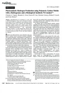
was obtained from Northern Industrial Tools that has the power output of 15 W. The solar panel can produce an output voltage of 22 V and a maximum current output of nearly 1.0 A. The output voltage was reduced by using a voltage regulating circuit. For the electrolyzer an output voltage of about 3.0 V was used. The (experimental arrangement is shown in Figure 1. The inclination of the solar panel was optimized to produce the maximum voltage output. The thermogravimetric analysis was performed using TA (Delaware) instrument in an oxygen atmosphere. A temperature ramp of 10 _C/min was programmed with oxygen gas flow at 10 ml/min. The cyclic voltammetry and Tafel measurements were carried out using Gamry electrochemical instrument. Table 1. Different Ni:MWCNT composites Composite
Ni (g)
MWCNT (g)
Composite
Ni (g)
MWCNT (g)
Ni-MWCNT (5:1)
0.18730
0.03746
Ni-MWCNT (4:1)
0.14980
0.03746
Ni-MWCNT (2:1)
0.07490
0.03746
Ni-MWCNT (1:1)
0.03746
0.03746
Figure 1 Electrolyzer made with Ni-MWCNT cathode Results and Discussion A review of the literature suggests that there are a number of metals and metal composites (3-27) have been investigated as cathodes for electrolysis of water. There are very few reports on the use of carbon nanomaterial composites for splitting water. A few studies in the literature are mainly directed towards spin polarization occurring with ferromagnetic materials (9,10) such as Fe,Co and Ni. The spin polarization of the ferromagnetic metal by the carbon nanotubes results in the protection of the metal from
25
Downloaded on 2015-08-05 to IP 129.21.161.210 address. Redistribution subject to ECS terms of use (see ecsdl.org/site/terms_use) unless CC License in place (see abstract).
ECS Transactions, 66 (30) 23-34 (2015)
oxidative corrosion. Of the three ferromagnetic metals, Ni is an electrochemically suitable material as it has better exchange current density for hydrogen ion reduction, although it has the potentiality for oxidation to oxide when in contact with oxygenated medium. Choosing Ni as the active material for the composite with MWCNT, we investigated the oxidative features of the composite through thermogravimetric studies before using it in the electrolytic splitting of water. Figure 2 shows the thermogravimetric recording of atomized nickel and the MWCNT composite of it. Nickel undergoes oxidation at temperatures above 500oC (Figure 2A) and results in the formation of nickel oxide. When it is composited with MWCNT, the oxidation of nickel is inhibited as shown Figure 2B. Table 2 gives the material performance in thermogravimetry. It shows that nickel oxidation onset occurs at 700oC due to the break down of the MWCNT. At this stage nickel undergoes oxidation to form its oxide. Thus these results show that the nickel composite is stable up to temperatures below 700oC. The stability of the nickel in MWCNT environment has been discussed as due to spin polarization by the MWCNT (30). The thermogravimetric data suggests that while atomized nickel oxidation is kinetically controlled which is hastened at higher temperatures, the composite shows stability to a greater extent as it requires the break down of the MWCNT before oxidation of nickel occurs.
Figure 2 Thermogravimetric curves of A)atomized nickel B) atomized nickel-MWCNT composite
Tafel Measurements The Ni-MWCNT active area is measured by examining the cyclic voltammetric oxidation of ferrocyanide of known concentration . Figure 3 shows a typical cyclic
26
Downloaded on 2015-08-05 to IP 129.21.161.210 address. Redistribution subject to ECS terms of use (see ecsdl.org/site/terms_use) unless CC License in place (see abstract).
ECS Transactions, 66 (30) 23-34 (2015)
voltammetric recording of potassium ferrocyanide solution at the composite electrode. Using the expression given in Bard and Faulkner (11) ip= (2.65 X10⁵) n3/2AD1/2C* v1/2
[1]
where ip is the peak current, n is the number of electrons, A is the area of the electrode, D is the diffusion coefficient, C* is the concentration of the ferrocyanide solution and Table 2 Thermogravimetric analysis of Ni Composites Composite
Condition
TGA weight at 800oC, mg
NiMWCNT (1:1) NiMWCNT (1:1) NiMWCNT (4:1)
Sintered 500oC, 1h
Sintered 500oC, 30 min Sintered 500oC, 30 min
Difference Lost, mg
Expected loss, mg
1.0249
Original Weight Ni (mg), MWCNT (mg) 1.352 1.352
1.679
1.352 (-0.327)
0.3110
0.778
0.7780
1.245
0.7780 (-0.467)
0.9854
2.066
0.5165
1.597
0.5165 (-0.4690)
Figure 3 Cyclic voltammetry of 10 mM K4Fe(CN)6 in 0.2 M KCl. Working Electrode: Ni-MWCNT Reference Electrode :SCE Sweep rate: 20 mV/s. v is the sweep rate, the area of the electrode has been calculated as 0.0745 cm2 using a diffusion coefficient of 0.65 X 10⁻⁵ cm2/s (11) and n=1. The rate of electron transfer has been evaluated using the methodology described by Klinger et al (31) which yielded a value of 1.75 X 10⁻³ cm/s.
27
Downloaded on 2015-08-05 to IP 129.21.161.210 address. Redistribution subject to ECS terms of use (see ecsdl.org/site/terms_use) unless CC License in place (see abstract).
ECS Transactions, 66 (30) 23-34 (2015)
The suitability of the Ni-MWCNT electrode for the electrolysis of water has been examined through Tafel plots with comparison to the other electrode materials reported in the literature. Figure 4 shows the Tafel plot in 1 M sodium sulfate as the electrolyte. An exchange current density value of 9.8 mA/cm2 was obtained in this medium for hydrogen ion reduction to hydrogen. The measurements carried out in sodium hydroxide and sulfuric acid media gave the exchange current densities of 6.5 mA/cm2 and 16.4 mA/cm2 respectively. The corresponding Tafel constants b values of 123 mV/dec, 110 mV/dec and 52 mV/dec were obtained in Na2SO4, H2SO4 and NaOH medium. In the literature there are a number of reports (29-32,35-47) giving the exchange current densities for hydrogen ion reduction on different metals. Table 3 gives a summary of those results. The exchange current density on Ni itself is low compared to the composites of Ni by orders of magnitude; NiMo46 functioning as cathode gave the highest performance with the exchange current density of 5.43 mA/cm2. In this study the exchange current density of Ni as reference produced an exchange current density of 0.18 mA/cm2. This denotes a change of nearly 30 times by Mo inclusion into Ni.
Figure 4 Tafel curve of Ni-MWCNT cathode in 1 M Na2SO4 at 25oC. The analysis of the Tafel curves has been used in the literature to understand the mechanism of hydrogen evolution (26-29). In the following reaction (2) involves direct electron transfer at the electrode as a rate determining step and has been proposed by Volmer for metals that is extended to the composites in the reactions below. NC + H+ + e-� NC-Hads NC-Hads +H+ +e- � NC +H2(g) NC-Hads + NC-Hads � 2NC +H2(g)
28
[2] [3] [4]
Downloaded on 2015-08-05 to IP 129.21.161.210 address. Redistribution subject to ECS terms of use (see ecsdl.org/site/terms_use) unless CC License in place (see abstract).
ECS Transactions, 66 (30) 23-34 (2015)
where NC is nanocomposite such as Ni-MWCNT. The theoretical models predict a negative slope in the range of RT/2F to RT/F at low overpotentials and 2RT/F to 3RT/F for intermediate overpotentials (31,32). In the literature this has been transformed to a slope of -116 mV for Volmer reaction (1) and Volmer-Heyrovsky reactions (reactions 2 and 3) yielding a slope of 29-30 mV/decade (22-27). Based on Tafel plots, the charge transfer step by reaction (2) appears to be the rate determining step in the hydrogen ion Table 3 Exchange current densities for hydrogen evolution Ni Electrode Ni
25oC
KOH(30%) KOH(6M) KOH(5M) KOH(1M) KOH(1M) NaOH(1M)
io (mA/cm2) 1.21 0.11 0.18 1 X10⁻³ 2.0 X10⁻³ 3.6 X 10⁻³ 2.66 X 10⁻² 40.9 22.6 5.38 7.7 X10⁻² 5.43 1.62 9.3 6.5
Ni-MWCNT
25oC
Na2SO4(1M)
9.8
Ni-MWCNT
25oC
H2SO4(1M)
16.4
Mild Steel Ni-P10 Pt Pt-Ce Pt-Sm Ni-S Ni-Fe Ni-Mo46 NiCoZn NiMn-PtRu Ni-MWCNT
Substrate
Temperature 25oC
Medium NaOH (1M)
Mild steel
30oC 30oC 85oC
KOH (1M) NaOH(6M) NaOH(32%) KOH (8M)
Ni
25oC
Steel Cu
25oC
Reference 32,43 46 47 26 5,33 34 35 35
36
37 38 39 Present work Present work Present work
reduction to hydrogen at the Ni-MWCNT electrode. Electrolysis results
The electrolyzers were constructed with cathodes of different materials such as MWCNT alone and MWCNT composited with atomized nickel in different electrolytes. The coulombic efficiency of the electrolyzers showed differences with a good performance and stability in sodium sulfate electrolyte. Tables 4 and 5 give the performance data. The S.No. in the tables represent serial numbers of the experiments showing individual experiments to show the repeatability of experiments and the effect of current density.
29
Downloaded on 2015-08-05 to IP 129.21.161.210 address. Redistribution subject to ECS terms of use (see ecsdl.org/site/terms_use) unless CC License in place (see abstract).
ECS Transactions, 66 (30) 23-34 (2015)
Table 4 Medium:Na2SO4 S.No. Current Volume of Hydrogen Charge A/m2 hydrogen production (Coulombs) 1 2 gas (L/d) rate (L/d.m ) 1 59.9 0.0228 453 3.9732 2 59.9 0.0212 421 10.246 3 60.9 0.0194 386 8.7944 4 58.9 0.0202 401 10.1556 5 57.3 0.0216 430 9.7920 Pressure:1.0026 atm. Temperature: 296 K Cathode: Ni-MWCNT (5:1)
Table 5 Medium: H2SO4 S.No. Current Volume of Hydrogen Charge mA/cm2 hydrogen production (Coulombs) gas (cm3/h)1 rate (L/h.m2) 1 11.58 1.6100 31.9 10.134 2 5.59 0.4183 16.4 5.182 3 5.79 0.4648 16.6 5.834 4 5.81 0.4648 16.5 5.869 Pressure:1.0026 atm. Temperature: 296 K Cathode: Ni-MWCNT (5:1)
Efficiency η
75.36 68.29 63.56 66.83 68.53
Efficiency η
65.10 68.88 66.96 66.21
As discussed in the introduction, there are a number of reports of commercial electrolyzers operating in the coulombic efficiency of 35-50%. Munoz et al (44) made exhaustive study of the electrolyzers using stainless steel cathodes and arrived at hydrogen production rate of 5L/m2h. By relative comparison, the Ni:MWCNT composite electrode (Table 6) shows a superior performance. The energy efficiency as defined as a Table 6 Comparative Performance of Electrolyzers Medium Electrode Coulombic Energy Efficiency Efficiency (%) (%) Na2SO4 Ni:MWCNT (5:1) 67.96 34.2 Ni:MWCNT(2:1) 47.43 33.3 MWCNT 41.49 31.2 NaOH Ni:MWCNT (5:1) 58.23 44.2 Ni:MWCNT (2:1) 16.79 42.1 MWCNT 33.58 42.1 H2SO4 Ni:MWCNT (5:1) 66.79 45.2 Ni:MWCNT(2:1) 27.17 45.2 MWCNT 39.94 43.0
ratio of Gibbs free energy of hydrogen combustion (-237 kJ/mol) to the free energy of electrochemical process as given by equation (5). Table 5 gives the energy efficiency
30
Downloaded on 2015-08-05 to IP 129.21.161.210 address. Redistribution subject to ECS terms of use (see ecsdl.org/site/terms_use) unless CC License in place (see abstract).
ECS Transactions, 66 (30) 23-34 (2015)
η= { ∆Gcombustion/∆Gelec} X100
[5]
obtained with different cathodes. The efficiencies obtained here are comparable with other electrodes reported in the literature that range from 30-45% (45). The hydrogen production rate is compared in Table 7 with the other electrodes and media.
Solar Powered Electrolysis The solar panel was standardized for a maximum output by inclining it to the sun (Figure 1). The voltage output of the panel ranged from 23.06 Volts to 18.9 Volts. An o inclination of the panel is kept at about 30 for a maximum voltage of 23.06 V. The current output ranged from about 122 mA to 1.019 A depending on the panel inclination to the sun. Under constant sunlight (with no clouds interfering), the current and voltages remained constant over a period of time. In this arrangement, the solar panel provided a maximum current of about 755 mA to the electrolyzer and vigorous evolution of hydrogen and oxygen gases were seen at cathode and anode electrodes. Future experiments are planned to use the electrolyzers described in the earlier section in scaling up operation.
Effect of Carbon nanotubes It has been demonstrated in our earlier studies (10,30) of the ferromagnetic metal composites with carbon nanotubes, that the metal is surrounded by carbon and protects it from oxidation. This has been theoretically analyzed by density functional calculations (7). In the previous reports in the literature discussed earlier, the hydrogen evolution is
Table 7 Hydrogen production rate
Medium
Electrode
Na2SO4
NaOH
Phosphate pH 8.0 Nickel– cermet
Current mA/cm2
Reference
Ni:MWCNT (5:1) Ni:MWCNT(2:1) MWCNT Ni:MWCNT (5:1) Ni:MWCNT (2:1) MWCNT
Hydrogen Production rate L/h.m2 18.87 14.48 15.31 14.08 5.84 9.54
5.91 6.86 7.74 5.32 7.12 5.72
Present work
Stainless steel
5.0
0.39
5
Scandia-stabilized zirconia electrolytes
14.0 (calculated 90L/h;Area:64 cm2), 10 cell stack
380
4
Present work
reduced at nickel cathode due to the formation of its oxide. The spontaneous formation of nickel oxide has also been discussed. The thermogravimetric results suggest that even at elevated temperatures up to 600oC, nickel composite is free from oxidation.
31
Downloaded on 2015-08-05 to IP 129.21.161.210 address. Redistribution subject to ECS terms of use (see ecsdl.org/site/terms_use) unless CC License in place (see abstract).
ECS Transactions, 66 (30) 23-34 (2015)
Conclusion
A short review of electrolyzers for producing hydrogen, the electrochemical mechanism and the results obtained with atomized nickel-MWCNT composite as cathode suggest that the composite produces hydrogen at a faster rate than nickel. The exchange current density measurement made with this electrode gives a value of 9.8 mA/cm2. Thermogravimetric studies of the composite shows that it is stable from oxidation up to 600oC. Acknowledgement
The author thanks Mr. Nitin Karla and Mr. David O’nley for helping with electrolyzer experiments. I acknowledge the financial support provided by the National Science Foundation under Award No. 1335927 and NYSERDA grant on Rochester Regional Clean Energy Education Partnership.
References 1. R. Press, K.S.V. Santhanam, M.Miri, A. Bailey and G.Takacs, Introduction to Hydrogen Technology, Wiley, NJ (2009). 2. A. Zuttel, A. Remhof, A. Borgschulte and O. Friedrichs, Philosophical Transactions of the Royal Society, A: Mathematical, Physical & Engineering Sciences , 368, 3329 (2010). 3. D. Marcelo and A. Dell’Era, Int. J. Hydrogen Energy, 33, 3041 (2008). 4. J. S. Herring, J. O’Brien, C.M. Stoots, G.l. Hawkes, J.J. Hartvigsen and M. Shahnam, Int. J. Hydrogen Energy, 32, 440 (2007). 5. L. D. Munoz, A. Bergel, D. Feron and R. Basseguy, Int. J. Hydrogen Energy, 35, 8561 (2010). 6. M. A. Rosen and D. S. Scott, Int. J. Hydrogen Energy, 23, 653459 (1998). 7. V. Pe’rez-Herranz, M. Pe’rez-Page and R. Beneito, Int. J. Hydrogen Energy, 35, 912 (2010). 8. M.A. Rosen, Energy (Oxford, United Kingdom, 35(2), 1068 (2010). 9. S.B. Fagan, R. Mota, A.J.R. da Silva and A. Fazio, Phys. Rev. B, 67, 205414 (2003). 10. a) K.S.V. Santhanam, X. Chen and S. Gupta, J. Nanoscience and Nanotechnology, 14, 2842 (2014). b) M. Kumar, N. Rawat and K.S.V. Santhanam, Mat. Res. Soc. Symposium, Materials Research Society, Warandale, Pa (2006), Vol.899E, pp. 899-N07-01.1 11. A.J. Bard and L.R. Faulkner, Electrochemical Methods, Wiley, NJ, (2000). 12. S. Abanades, A. Legal, A. Cordier , G. Peraudeau, G. Flamant and A. Julbe, J. Mat. Sci., 45,4163 (2010). 13. K.C. Burch, D.M. Ginosar, M. Daniel, H.W. Rollins, R.R. Lewis, Abstracts of Papers, 238th ACS National Meeting, Washington, DC, United States, August 1620, (2009). 14. X. Vitart, P. Carles and P. Anzieu, Progress in Nuclear Energy, 50, 402 (2008) 15. D. Pletcher and X. Li, Int. J. Hydrogen Energy, 36 ,15089 (2011).
32
Downloaded on 2015-08-05 to IP 129.21.161.210 address. Redistribution subject to ECS terms of use (see ecsdl.org/site/terms_use) unless CC License in place (see abstract).
ECS Transactions, 66 (30) 23-34 (2015)
16. E. Lanzarini, M.R. Antognazza, M.Biso, A. Ansaldo, L. Laudato, P. Bruno, P. Metrangolo, G. Resnati, D. Ricci and G. Lanzani, J. Physical Chemistry C, 16, 10944 (2012). 17. I. Dincer and C. Acar, Int. J. Hydrogen Energy, 39, 1 (2014). 18. K. Mazloomi, N.B. Sulaiman, and H. Moayedi, Int. J. Electrochemical Science, 7, 3314 (2012). 19. M.Y. Lin, L.W. Hourng and C.W. Kuo, Int. J. Hydrogen Energy, 37 , 1311 (2012). 20. W.D. Gu, and Z.Y. Yan, Int. J. Hydrogen Energy, 37, 737 (2012). 21. M.Z. Shen, N. Bennett, Y.L. Ding, and K. Scott, Int. J. Hydrogen Energy, 36,14335 (2011). 22. A.D. Maksic, S.M. Miulovic, and V.M. Nikolic, I.M. Perovic and M.P.M. Kaninski, Applied Catalysis A-general, 405,25 (2011). 23. I. Herraiz-Cardona, E. Ortega, L. Vazquez-Gomez and V. Perez-Herranz, Int. J. Hydrogen Energy,36, 11578 (2011). 24. W.L. Guo, L. Li, L.L. Li, S. Tian, S.L. Liu and Y.P. Wu, Int. J. Hydrogen Energy, 36, 9415 (2011). 25. M.P.M. Kaninski, S.M. Miulovic, G.S. Tasic,A.D. Maksic and V.M., Int. J. Hydrogen Energy,36, 5227 (2011). 26. M.P.M. Kaninski, V.M. Nikolic, G.S. Tasic and Z.L. Rakocevic, Int. J. Hydrogen Energy, 34, 703 (2009). 27. D. Buddhi, R. Kothari and R.L. Sawhney, Int. J. Green Energy, 3, 381 (2006). 28. A.J. Bard, J. Am. Chem. Soc., 132, 7559 (2010). 29. M.S. ElDeab, M.E. ElShakre, B.E. ElAnadouli and B.G. Ateya, J. Applied Electrochem., 26, 1133-1137 (1996). 30. K. S. V. Santhanam, Xu Chen, and S. Gupta J. Nanosci. Nanotechnol. 14, 28422851 (2014). 31. R.J. Klingler and J.K. Kochi, J. Phys. Chem., 85, 1731 (1981). 32. J.M. Jaksi, M.V. Vojnovi, V. Krstaji, Electrochim. Acta, 45,4151(2000). 33. I. Arul Raj, Appl Surf Sci., 59, 245 (1992). 34. S.M.A. Shibli and V.S. Dilimon VS. , Int J Hydrogen Energy, 32, 1694 (2007). 35. D.M.F. Santos, C.A.C. Sequeira, D. Maccio,A. Saccone and J.L. Figueiredo, Int J Hydrogen Energy, 38,3137 (2013). 36. Z. Shan , Y. Liu, Z. Chen, G. Warrender and J. Tian, Int J Hydrogen Energy, 33, 28 (2008). 37. J. Kubisztal, A. Budniok, A. Lasia , Int J Hydrogen Energy, 32, 1211( 2007). 38. R. Solmaz and G. Kardas, Int J Hydrogen Energy , 36, 12079 (2011). 39. A.O. Yuce, A. Doner and G. Kardas, Int J Hydrogen Energy,38,4466 (2013). 40. M.R Gennero de Chialvo, A.C Chialvo, Electrochemistry Communications, 1, 379 (1999). 41. S. Trasatti, Electrocatalysis of hydrogen evolution: progress in cathode activation, in: H. Gerischer, C.W. Tobias (Eds.), Advances in Electrochemical Science and Engineering, vol. 2, VCH, 1992. 42. B. Børresen , G. Hagen and R. Tunold, Electrochimica Acta, 47, 1819 (2002). 43. I.M. Kodintsev, S. Trasatti, Electrochim. Acta , 39, 1803 (1994).
33
Downloaded on 2015-08-05 to IP 129.21.161.210 address. Redistribution subject to ECS terms of use (see ecsdl.org/site/terms_use) unless CC License in place (see abstract).
ECS Transactions, 66 (30) 23-34 (2015)
44. L. D. Muñoz, A. Bergel, D. Féron and R. Basséguy, Int. J. Hydrogen Energy, 35, 8561 (2010). 45. B.Yildiz and M.S. Kazimi, Int. J. Hydrogen Energy, 31, 77 (2006). 46. M. H. Miles, G. Kissel, P. W. T. Lu, and S. Srinivasan, J. Electrochem. Soc., 123, 1858 (1976). 47. B. Pierozynski, Int. J. Electrochem. Sci., 6, 63 (2011).
34
Downloaded on 2015-08-05 to IP 129.21.161.210 address. Redistribution subject to ECS terms of use (see ecsdl.org/site/terms_use) unless CC License in place (see abstract).