The switching pressure on a domain wall is given by the difference in free energy ... a custom-modified Gatan single-tilt holder that allowed application of electric ...
Efficient Switching and Domain Interlocking
arXiv:cond-mat/0106173v1 [cond-mat.mtrl-sci] 8 Jun 2001
Observed in Polyaxial Ferroelectrics A. Krishnan,1 M.M.J. Treacy,1 M.E. Bisher,1 P. Chandra1 and P.B. Littlewood2 1 NEC
Research Institute, 4 Independence Way, Princeton NJ 08540
2 Cavendish
Laboratory, Madingley Road, Cambridge CB3 OHE, UK
Abstract We present transmission electron microscopy observations of domain wall motion in thin freestanding KNbO3 crystals under applied electric fields. Since there is no substrate, there is no elastic clamping of 90◦ domains. We observe that curved and tilted 90◦ domain walls are the most mobile, whereas untilted 90◦ domain walls are resistant to field-induced motion. We explain this result in terms of two factors. First, the switching pressure on a domain wall (P 2 −P 1 )·E is determined by the relative electrostatic
energies of the neighboring polarizations P 1 and P 2 . Consequently, some 90◦
domain walls are immobile under certain field directions, leading to domain interlocking. Second, domain walls experiencing a high switching pressure move by a ripple mechanism, and do not move as rigid sheets. The tilted wall region in such a ripple has a polarization charge, and an associated depolarization field, which reduces the local switching barrier. An accumulation of polarization charge can result in a tilted or curved wall, as occurs at the mobile tips of 90◦ domain needles. Any increase in density of immobile wall configurations with cycle time represents an inherent contribution to fatigue. Uniaxial ferroelectrics, with polarizations parallel to the field, should not experience such domain interlocking.
1
I. INTRODUCTION
Ferroelectric materials are attracting much interest because of their potential use as nonvolatile computer memories [1]. However, the physical processes that lead to degradation effects, such as fatigue and imprint, are still incompletely understood and represent significant barriers to the development of ferroelectric devices. Ferroelectric fatigue appears as a gradual reduction of the switchable polarization with time, whereas imprint occurs when one polarization direction requires a larger coercive field than does the reverse polarization. It is clear that fatigue is due, in part, to the suppressed motion of domain boundaries, which inhibits the polarization reversal processes. The link between the increased density of unswitchable domains and fatigue has been established by direct observation using atomic force microscopy [2]. Several contributions to the degradation of ferroelectric capacitors have been identified, leading to the development of improved devices [3–7]; these include charge accumulation near the electrodes [8], and electromigration of extrinsic pinning centers such as charged defects [9] and oxygen vacancies [10]. In this paper, we present in-situ transmission electron microscope (TEM) observations on single crystal KNbO3 which indicate that domain wall motion can be inhibited in homogeneous polyaxial ferroelectrics. Our studies are conducted at temperatures much less than the Curie temperature in electric fields that are well below the nominal coercive value. In our experiments, the ferroelectrics are freestanding and are not clamped by any support material. The observed domain configurations are robust to mechanical tapping, and in the absence of an electric field, are stable for long periods of time. No spontaneous nucleation is observed, implying that switching is dominated by domain wall motion. The switching pressure on a domain wall is given by the difference in free energy of small regions either side of the wall. We observe that in a polyaxial ferroelectric, where many different domain wall orientations can occur, not all domains of a given polarization are equally switchable under a fixed electric field. In particular, if the field direction is reversed, the domain response changes. Although elastic interactions are clearly important 2
in the energetics of switching, this observed behavior cannot be explained by piezoelectric interactions alone, since at equilibrium the strain energy depends only on even orders of the polarization and is not very sensitive to changes in wall domain orientation and electric field direction. By contrast, the electrostatic energy difference, (P 2 −P 1 )·E, across a wall bordering domains of polarization P 1 and P 2 is affected by the field direction. Consequently, not all walls are equally mobile. Therefore, in a polyaxial ferroelectric, not all domains of a given polarization are equally switchable under an applied electric field. In this paper we explain our results phenomenologically in terms of the electrostatic energy contributions. Although elastic energies are clearly important, they alone cannot explain the observed neighbor-dependent switching efficiency of domains. This implies an inherent distribution of coercive fields for domain switching. Our results suggest that polyaxial ferroelectrics are vulnerable to any redistribution of domain size and configuration with cycle time that leads to an increase in density of the most inhibited domain configurations. We discuss the implications for fatigue and imprint in polyaxial ferroelectrics.
II. EXPERIMENTAL RESULTS
In-situ TEM studies of ferroelectrics provide an opportunity to observe extended areas of domain structure at high resolution while simultaneously modifying external parameters [11–14]. Here we report results from observations of freestanding single-crystal potassium niobate KNbO3 , noting that we have seen similar phenomena in single-crystal barium titanate BaTiO3 . All experiments were performed in a Hitachi H9000-NAR TEM at 300 kV at room temperature, well below the Curie temperature Tc . The samples were mounted in a custom-modified Gatan single-tilt holder that allowed application of electric fields to the sample during observation. In the absence of electric fields, domain configurations are stable to mechanical handling. Experimental details have been reported elsewhere [15]. Figure 1 shows micrographs of an area of thin KNbO3 , viewed along one of the principal pseudo-cubic h100i axes, before and after application of an electric field. Prior to acquiring 3
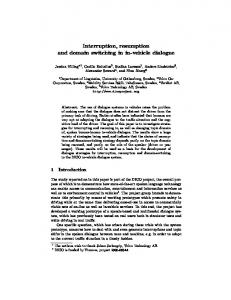
this pair of micrographs, the specimen was subjected to approximately ten field cyclings, and thus Fig. 1a does not represent a virgin state. The in-plane direction of the electric field, as determined by the electrode geometry, is indicated. There is also a vertical (i.e. into the page) component of the field. The amplitude of the field in this region is estimated to be < 0.2 V.µm−1 . As frequently happens in these domain switching experiments, the region of interest moved rapidly out of the field of view when the electric field was applied. Consequently, this leaves us with just the before and after views. Those domain walls that are aligned edge-on to the viewing direction show up as dark thin lines primarily because of diffraction contrast caused by shear strain across the boundary. Although KNbO3 can support many types of domain wall structure, the area shown in Fig. 1 is dominated by 90◦ and 180◦ domain walls, which are the most common. Initially (Fig. 1a) we observe many needle-like 90◦ domain walls that are pinned at their tips by a third domain orientation; by 90◦ and 180◦ we refer to the approximate relative angle between polarization vectors, P 1 and P 2 , adjacent to a given boundary. The polarization charge surface density, σ = ∆P ⊥ = (P 1−P 2 )·ˆ n, associated with a domain wall is zero if the normal component of the polarization, P·ˆ n, is continuous across the interface. Here, n ˆ is the unit vector normal to the wall into domain P 2 . Curvature in domain boundaries inevitably implies discontinuities in P ·ˆ n across parts of the boundary, resulting in non-uniformly charged walls and the possibility of increased mobility under an applied electric field, E. We note that in both KNbO3 and BaTiO3 the observed domain patterns are stable to mechanical perturbations and to thermal cycling within the ferroelectric phase [15], indicating that ferroelastic effects do not dominate the observed domain behavior. The weak, but observable, contrast at both the 90◦ and charge-neutral 180◦ domain walls is confirmed by standard multislice TEM image simulations [16]. In Figs. 1c(d) we delineate the relevant domain boundaries observed in the micrographs, along with the associated polarization directions and boundary charges. Selected area diffraction confirms the orientation of the polarization axes to within an ambiguity of ±180◦ . For consistency with the known electric field direction, we associate positive charge with the curved domain boundaries A1 , A2 , C1 , C2 , C3 whereas the straight interfaces along the diag4
onal wall are neutral. This interpretation is confirmed by temporary application of a weak electric field, as displayed in Figs. 1b and 1d (the field is switched off in Fig. 1d). Here we observe that curved boundaries and associated tips have moved, whereas the neutral 180◦ and 90◦ interfaces (e.g. B1 ) have undergone little change, suggesting that an applied electric field has maximum effect on curved and tilted walls. We have micrographs of qualitatively similar field-induced domain behavior in BaTiO3 , although the details of needle shape and relative abundance of 90◦ and 180◦ walls are different.
III. DISCUSSION
Domain walls can minimize electrostatic energy by maintaining continuity of the normal ˆ across the wall. This condition ensures zero polarization component of polarization P · n charge density on the wall and consequently no local contribution to the depolarization field. However, if the domain wall were tilted by an angle θ relative to the ideal angle (see Figure 2) then a charge density σ is developed. Ignoring small corrections due to deviations from √ true cubic symmetry, the surface charge density at 90◦ domains (Fig. 2a) is σ90 = 2P sin θ, and at 180◦ domains (Fig. 2b) is σ180 = 2P sin θ. We observe experimentally in KNbO3 and BaTiO3 that domain wall curvature and tilt often occurs when perpendicular sets of 90◦ domains intersect. Such tip curvature can result from a competition between minimization of the electrostatic energy (UE ∝
R
σ 2 dA) and
conservation of polarization charge (Q ∼ σdA) at the interrupted domain tip. We illustrate R
this point in Figure 3 for the simplest case of planar polarization. Figure 3a shows a sketch of two 90◦ domain orientations A and B where a third, C, is contained in B. The interface √ between A and C is a 180◦ tilted (θ ≈ 45◦ ) wall with polarization charge density σ ≈ 2P per unit area. Naturally this charge density can be eliminated if all of C transforms into B. The positive polarization charge then will flow to the opposite tip of domain C (or, conversely, negative polarization charge could flow from the opposite tip, with the same end result), and the polarization component B increases. The electrostatic energy of the configuration in 5
Fig. 3a can be lowered, while preserving approximately the total polarization, by curving the interfaces enclosing C. The resulting non-uniform charge density reduces UE and involves a redistribution of the boundaries between B and C. Alternatively, the wall between A and C can also tilt through 45◦ (Fig. 3c), resulting in a zero polarization charge density, σ = ∆P ⊥ = (P 1 −P 2 )· n ˆ = 0, everywhere. To accomplish such domain wall restructuring, with zero charge at the interfaces, a negative polarization charge must flow in from the left and right boundaries. The development of this charge-neutral pattern requires motion of the boundaries between A and B. The relative importance of these configurations depends on the energetic barriers between the different polarization domains A, B and C, and here elastic effects could play an important role. In multicomponent ferroelectrics, the spontaneous polarization is accompanied by a local deformation which, for simplicity, we do not treat directly in the present discussion. Similar needle-like domain structures to those discussed here (see Figure 3b) also arise in ferroelastics [17] and martensitics [18] due to competition between topological and long-range elastic effects. In the context of ferroelectrics we emphasize the polarization charge associated with such configurations, since this charge is crucial towards understanding their field-induced response. Under an applied electric field E, domains switch so as to reduce the polarization energy, UP = −P ·E. However, at temperatures well below the Curie temperature, Tc , there is a barrier to switching. Above the coercive field, this barrier disappears and switching occurs effortlessly. Our in-situ data, however, is acquired at fields well below the theoretical coercive field, and indicates that switching is dominated by domain wall motion rather than by spontaneous domain creation. The switching pressure on the wall separating two domains with polarizations P 1 and P 2 is given by (P 2 −P 1 )·E. This pressure is dependent on field direction, and can be zero. In the micrographs of Figure 1, the fact that the domain walls at A1 , A2 etc. are curved and tilted indicates that those parts of the wall are moving. These walls therefore, must be experiencing higher switching pressures than the straight walls, suchas those at B1 . 6
In the appendix, we present a simple isotropic Landau-Ginsburg Free energy analysis of a tilted 180◦ domain wall that is subjected to applied field. The analysis confirms that there are two effects caused by wall tilt, both of which increase the wall mobility under an applied electric field. First, the polarization energy term P · E is enhanced by a factor 1 + g(θ). This enhancement counteracts the reduction in local P caused by the depolarization field. Consequently, the pressure term (1 + g(θ)) P ·E is approximately independent of angle and roughly equal to P 0 ·E at all wall tilt angles θ, as expected. The second is that the effective Curie temperature is lowered, which means that the switching barrier height ∆Fbarrier , which is of the order of kB T˜c (θ), is lowered. Untilted, charge-neutral, walls have the highest barriers to switching. Realistically, depolarization fields will be screened at large lengthscales, particularly in thin films, but will continue to influence the polarizations adjacent to the wall under study. The preceding free energy argument provides insight into the field-induced motion of needle-like domains such as those shown in Fig. 1b(d). The curved tip of the needle supports a polarization charge that increases with tilt and is maximum at the horizontal wall of the tip (where θ = 90◦ , with θ1 = 0◦ ). In the absence of an electric field, the switching barrier at the tip is reduced compared with the uncharged needle sides. Consequently, the effective coercive field at the tip is lower than that of the flat sides. Under an applied field, the tip moves first, since the electrostatic pressure is approximately constant over the wall, and the barrier is lowest at the polarization-charged tip. It is believed that domain walls are unstable under finite electrostatic pressure [19], and ripples can appear. In order for the needle to retract, the tip must transfer its charge to lower parts of the wall. Most likely, the tip achieves this charge transfer by emitting a series of charged ripples which flow along the wall [20]. These ripples can propagate because the local charge at the ripple increases the local wall angle, concomitantly reducing the local switching barrier and increasing the local switching pressure. Locally, after the ripple has passed, the wall has moved sideways thus increasing the volume of polarization energetically favored by the applied field. From another perspective, these charge ripples result from local nucleation events at domain walls, and a 7
number of experiments suggest that lateral domain motion is controlled by these processes [21–23]. In particular, the measured exponential field-dependence of the wall velocity gives strong support to this scenario [23]. We now apply this understanding to the data shown in Figure 1. Figure 4 illustrates schematically an interlocked domain system in a similar orientation to that observed in Fig. 1. Three out of the four possible in-plane polarization directions are present. Domains A, B and C have the same polarization, with A and B forming vertical needles bordering 90◦ domains D, E and F, whereas C forms a horizontal needle bordered by 90◦ domains G and H, which have antiparallel polarization to D, E and F. Domains antiparallel to A, B and C are not present. In this diagram the electric field moves positive charge from top to bottom, and this flow is represented here as ripples of polarization charge ∆QD along the diagonal domain wall labeled 1–2–3–4–5. Charge flows from the upper left corner until it reaches the tip of domain A (region 2 in Fig. 4a). Domain A presents two additional domain wall surfaces along which charge flow can branch. Domain A cannot detach until a minimum charge has been accumulated (Fig. 4b), which is proportional to its width W . In addition, the charge accumulating near the tip 2 will generate a local depolarizing field which may act to decrease the flow of polarization current along the diagonal wall. Once domain A detaches, and its tip region 2 begins to retract (Fig. 4c), it carries a fixed polarization charge. The end of domain A transforms into a pointed tip in order to spread the fixed polarization charge Q =
R
σdA over a larger surface area so as to reduce the charge
density, σ, and hence the electrostatic energy, UE ∝
R
σ 2 dA. The charged ripples from the
electrode now continue along the diagonal wall, 1–3–4–5, to the tip of domain B (region 3 in Fig. 4d). The walls between domains B and G, and B and H, can support positive charge ripples which would shrink B. However, there is no driving force to propagate such ripples since the pressure on the wall (P G −P B )·E ≈ 0. There is no energy reduction obtained by switching B. Consequently, the charge flows past B, moving its tip 3 by an amount equal to the ripple height, but leaving the tip shape unaffected. The charge ripple moves on to domain C (Figs. 4e and 4f), which subsequently behaves similarly to domain A. In the 8
meantime, the tip of domain A has been retracting at a constant rate due to electrostatic pressure from the electrodes. Although A, B and C have equivalent polarization orientations, it is clear that they are not equally mobile. The curved tip of A can move parallel to the field in order to reduce the total polarization energy of the system, whereas the motion of B would be perpendicular to the field, with no reduction in overall energy. There is no switching force on the wall separating B and G. The B/G and B/H walls are intrinsically inhibited by the environment of domain B. B can only reduce its energy by switching to the orientation of domain E at its tip, and that switching rate is governed by the motion of the wall 1–2–3–4–5. Such intrinsically domain-interlocked configurations can reduce the amount of switchable polarization. We note that nonlinear field effects can induce boundary polarization charge [24], supporting the observation that periodic high-field pulses relieve ferroelectric fatigue [25]. We have observed that fine-scale domain fingering patterns move faster than larger ones, consistent with the notion of curvature-dependent charge densities. Current theories of ferroelectric switching times assume geometrically-independent domain velocities [6]; the observations here clearly point to the limitations of such approaches. The sign and direction of the charge ripples in a particular domain configuration are important. Figure 5a depicts the same region as in Figure 4a, under the same electric field, but this time the diagonal wall is carrying negative charge in the opposite direction, 5–4– 3–2–1. Following a similar reasoning as that for Fig. 4, we find that the principal difference in behavior is that in Figure 4, domain A detaches first, whereas in Figure 5, domain C detaches first. For different domain configurations and field orientations, the asymmetry in field response could be quite large, and thus might be an inherent contribution to imprint. The illustrative example described above shares many similarities with the domain wall behavior observed in Figure 1. The domains A1 and A2 are analogous to domain A in Figure 4; similarly B1 is analogous to B and C1 , C2 and C3 are analogous to C. The domains A1 and A2 have retracted the furthest under the field, whereas C1 , C2 and C3 have traveled the least distance. B1 is relatively unaffected by the field. The position of the five tips is 9
consistent with A1 having detached first, followed by A2 etc. and with subsequent uniform field-induced tip motion. The switching rate of B1 is determined entirely by the charge flow along the diagonal wall through its tip, and is therefore an indirect multi-step process. Charge ripples play a loosely analogous role to that of dislocations in the plastic deformation of crystals, where it is considerably easier to propagate a single dislocation over a slip plane, than it is to shear a whole region of the crystal over the same plane in one movement. The end result is the same, but the barrier to dislocation motion along the slip plane is significantly lower and is therefore much more likely to occur. Our observations demonstrate that the switchability of an unsupported ferroelectric depends on the distribution of domain orientations and their widths. More specifically, the charge threshold required for the field-induced depinning of a domain is proportional to its width, so domains of the type A and C in Figure 4 retract and hence switch more readily than their wider counterparts. By contrast, a domain of type B in Figure 4, identical in polarization orientation to that of A and C, requires multi-step switching processes since the polarization orientations of its neighbors make direct switching energetically unfavorable. The switchability of a particular domain then depends not only on the specifics of its own polarization orientation, but also on its possible final states as defined by its adjacent polarizations. We also note that there is an anisotropy in the intrinsic switching mechanism described here. In Figure 4 if the field were applied parallel to the diagonal wall, i.e. from the upper left to the lower right, then the relative mobility of domains A, B and C changes. Some crystal orientations will be less vulnerable to inhibition of domain switching. This conclusion is consistent with recent experiments which exhibit fatigue anisotropy in single-crystal ferroelectrics [26]. It follows from our model that if the electric field were to be rotated 90◦ , the roles of mobile and jammed domains would reverse. If the field were applied from right to left in Figure 4, domain B would form a negatively charged mobile tip which would retract to the right. A, C, D, E and F are now the interlocked domains. This suggests that the periodic application of a perpendicular field would provide a method for flushing out domain-locked regions in a fatigued polyaxial ferroelectric. Earlier experiments 10
on thin films of fatigued lead zirconate titanate show that unfatigued ferroelectric properties are indeed measured when the applied electric field is changed by 90◦ [27]. It is well-known that the experimental coercive field is significantly lower than the predicted theoretical value [21]. As we have shown, a tilted wall has a reduced coercive field compared to its untilted counterpart because of the associated depolarization field. The relevant angles to consider are not the static wall tilt angles observed in our micrographs. Instead, they are the angles adopted by the propagating charge ripples. We expect that these field-dependent angles could be large, since the ability of the charged ripple to propagate requires a highly reduced switching barrier. We have not observed such charge ripples directly in our experiments, since they move rapidly and could be of small amplitude, and so we can not make a quantitative analysis of this contribution. However, it is clear that domain walls do not move as rigid structures, and that therefore polarization charges are necessarily involved in domain wall motion. Many models of ferroelectric fatigue involve the electromigration of extrinsic pinning centers that suppress domain motion and hence polarization reversal [28–31]. In zero-applied field we frequently observe domain walls entangled with dislocations, such as shown in Figure 6. Curved and tilted domain walls can attract migrating charged defects electrostatically to neutralize their surface charges. Our studies indicate that these needle-like domains are highly mobile in an applied field, and can move towards extrinsic charge centers that are essentially stationary on the appropriate short time-scale [32]. The different domain behaviors we observe in our experiments are definitely not elastic stress-related phenomena, since our samples are freestanding single crystals. The electrodes are not in intimate contact with the regions being observed. Domain clamping by electrodes [33], although crucially important in epitaxially grown ferroelectric systems, does not occur in our experiments. Stresses are indeed present in our samples. The tip structures labeled 2, 3 and 4 in Figure 4a, are similar for both mobile and immobile needles, and resemble the charge-neutral conformation shown in Figure 3c. As in ferroelastics, there can be large stresses associated with such triple domain junctions [17,34] However, such stresses are 11
qualitatively similar for all tip structures, regardless of domain orientation with respect to the applied electric field, and can not explain the difference in their field-induced mobility. We expect that the domain behavior we observe is characteristic of a ferroelectric system that is not mechanically clamped. Examples would be polycrystalline films, and films with low Young’s modulus contact electrodes, such as liquids and some conducting oxides.
IV. CONCLUSIONS
We have presented evidence, using in-situ transmission microscopy on freestanding KNbO3 and BaTiO3 samples, that in a polyaxial ferroelectric not all domains of a given polarization orientation are equally switchable in low applied fields. Angled and curved domain walls are abundant, and often occur when perpendicular sets of 90◦ intersect. We can understand the observed domain configurations as resulting from a competition between the minimization of the electrostatic energy and conservation of the polarization charge. In our experiments, domain switching occurs as a fluid, non-rigid, wall motion and all observed domain patterns are stable to mechanical tapping. Spontaneous domain creation is never observed at fields well below the coercive field. The switching efficiency of a particular domain is determined by its allowed final states which are defined by its neighbors. If the relative energetics are unfavorable, switching will be inhibited. Such domain interlocking results in a reduction of the switchable volume in the sample, and provides an inherent contribution to degradation effects in polyaxial ferroelectrics. The sequential depinning of domain needle tips that we observe in BaTiO3 and KNbO3 under applied electric fields, reveals that polarization charge must be flowing along domain walls that are experiencing an electrostatic switching pressure. Polarization charge ripples facilitate domain switching in a manner roughly analogous to the role played by dislocations in crystal slip. Mobile needle-like domains retract in applied fields because of the reduced switching barriers at the tips. Inhibited domains have an environment that energetically prohibits the formation of a charged tip and thus require indirect switching processes. Rotation of 12
the direction of the applied electric field through 90◦ should free such inhibited domains. In addition, complex interactions with mobile extrinsic charges can further inhibit the retraction of intrinsically charged needles. Such processes could contribute to a reduction in the dipolar screening charge flowing in the external circuit to the electrodes, and thus could contribute to ferroelectric fatigue and possibly imprint. Domain interlocking is less likely to occur in ferroelectrics with reduced degrees of polarization freedom. We expect that ferroelectric fatigue will be greatly diminished in materials with a single preferred polarization axis, possibly induced by application of stress or field. We thank S. Bhattacharya, J. D. Chadi and J. F. Scott for stimulating discussions.
13
V. APPENDIX
Impact of wall tilt on switching barrier and switching pressure. We examine the simple isotropic Landau-Ginsburg free energy of a freestanding ferroelectric region close to a 180◦ domain wall that is tilted from the charge-neutral orientation by an angle θ. Figure 7a shows a model ferroelectric capacitor with a 180◦ domain wall perpendicular to the electrodes. The wall has been sheared slightly such that, near the middle of the wall, a small region has tilted through an angle θ. Far from the wall, the polarizations in each domain are ±P 0 , parallel and antiparallel to the electrode normals. A surface polarization charge develops at the tilted wall region. However, the charge at the wall is not simply ˆ associated with the wall charge, σ = 2P0 sin θ. There is a depolarization field E w = Ew n ˆ to be the unit that depolarizes the local polarizations to P 1 = ±(P 0 + ∆P ). Assigning n vector along the tilted wall normal, the self-consistent surface charge σw at the wall is, ˆ σw = [(−P 0 + ∆P ) − (+P 0 + ∆P )]· n ˆ − 2ǫ0 χEw n· ˆ n ˆ = −2P 0 · n = 2P0 sin θ − 2ǫ0 χEw .
(1)
The electric field Ew is also related to the surface charge σw by Ew =
σw . 2ǫǫ0
(2)
The field is of opposite sign in each domain, and can be considered constant out to a distance equal to the wall length, i.e. within the cylindrical region shown in Figure 7b. Substituting for Ew into equation (1) gives σw =
2P0 sin θ ≈ P0 sin θ 1 + χ/ǫ
and
14
(3)
Ew =
P0 sin θ P0 sin θ ≈ . ǫǫ0 (1 + χ/ǫ) 2ǫǫ0
(4)
Thus, in the limit of large ǫ, the depolarization field Ew acts to reduce the wall charge to about half of its nominal value, 2P0 sin θ. The depolarization field results in the local polarization vectors being tilted away from the wall by an amount θ1 . θ1 is found from the triangle defined by P 0 , P 1 and ∆P in Figure 7b, from which we get the sine rule relations P1 χP1 sin(θ−θ1 ) P0 = = cos(θ−θ1 ) cos θ ǫ sin θ1
(5)
which give cos θ sin(θ−θ1 ) −
ǫ sin θ1 = 0. χ
(6)
There is an additional volume charge that appears away from the domain wall. Far from the tilted wall, the polarization returns to the bulk value P 0 . The associated ∇·P gives rise to a volume polarization charge. The total volume charge is equivalent to the charge “missing” from the wall due to depolarization, thus the total wall plus volume charge equals 2P0 sin θ times the tilted wall area. An additional complication is imposed by the equipotential boundary conditions at the electrodes. These boundary conditions are equivalent to creating mirror images of the charged region. We have assumed that the multipole contributions to the local field can be ignored. The surface charge density on a wall of fixed tilt is independent of the electric field, and equal to σ = 2P 1 sin(θ−θ1 ). This can be rewritten in terms of the local polarization P as σ = 2|P −ǫ0 χE| sin(θ −θ1 ) (see Figure 7b). (P = P L or P R depending on which domain we are considering.) Incorporating the depolarization energy, UW = 21 ǫǫ0 Ew2 into a standard Landau-Ginsburg free energy expansion, we obtain for the regions either side of a tilted 180◦ domain wall i 1 h β 1 1 F ≈ α T − T˜c (θ) P 2 + P 4 + γP 6 − [1 + g(θ)] P ·E + µξ 2 (∇·P )2 2 4 6 2
15
(7)
where the reduced effective Curie temperature T˜c (θ) is given by T˜c (θ) = Tc −g(θ)/ǫǫ0 α, with g(θ) = sin2 (θ−θ1 ). Since the regions of interest are just either side of the domain wall, at a distance much closer than the characteristic length scale ξ for depolarization field gradients, the last term is essentially negligible. From this simple isotropic analysis, it emerges that one effect of wall tilt on a 180◦ domain is to reduce the barrier to switching by decreasing the effective Curie temperature T˜c (θ) of domain regions close to the tilted wall. In addition, the term corresponding to the electrostatic pressure on the wall is enhanced by a factor [1 + g(θ)]. This enhancement has the effect of maintaining an approximately constant electrostatic pressure 2P 0 · E on the tilted wall, despite the fact that the local polarization P 1 is reduced by the depolarization field. The expression for the effective Curie temperature T˜c = Tc −ηg(θ), where η = 1/ǫǫ0 α (≡ 4π/ǫα c.g.s.), that emerges from equation (7) indicates that there exists a threshold angle, defined by g(θ¯T ) = (Tc −T )/η, at each temperature delineating the ferroelectric and paraelectric phases. The presence of θ¯T is consistent with our TEM studies, which show ∗ ≤ 7◦ . Noting typical domain tip angles in BaTiO3 of θB∗ = 5 ± 1.4◦ and in KNbO3 of θK
that η = C/ǫ, where C is the Curie constant, we find using standard values [21] for C and ǫ ∗ for BaTiO3 and KNbO3 , that ηK < ηB ; thus the observation that θK > θB∗ is consistent with
our expectations from this phenomenological approach [35]. The coercive field, Ec (θ), required to move a tilted 180◦ domain wall varies with θ as "
ηg(θ) Ec (0) 1− Ec (θ) = [1 + g(θ)] Tc − T − ηg(θ)
#3/2
.
(8)
Since 0 ≤ g(θ) ≤ 1, g(θ) acts to reduce Ec (θ) locally. Again, there exists a threshold angle at each temperature, θ¯E < θ¯T defined by g(θ¯E ) = (Tc − T )/2η, above which there is fieldinduced switching. This angular dependence could provide a major contribution to the spread in coercive fields observed in standard hysteresis loops. A more complete free energy expression would incorporate anisotropy in both the polarization and stress fields. Such refinements are important for modeling the detailed be16
havior and shape of domain needles in different materials. Strain energy is particularly important for materials supported on stiff substrates where domain clamping effects dominate. Isotropic elastic strain fields are long-range and, unlike the electric fields, can not be screened. They are expected to increase switching barriers overall [36], but should not affect the angular dependencies discussed here. Clearly, they will not affect the electrostatic pressure. In our experiments, the ferroelectrics are freestanding and are not clamped by any support material. Further, the initial tip structures are similar for both mobile and immobile needles (i.e. Domains A and C versus domain B in figure 1). Elastic constraints caused by tip stresses are expected to be similar for all these domains, and therefore can not explain the different domain behaviors in the isotropic limit. Thus the simplified isotropic treatment presented here is adequate for understanding the underlying physical insights revealed by our data.
17
REFERENCES [1] J.F. Scott, Ferroelectric Memories (Springer-Verlag, Berlin, 2000). [2] E.L. Colla, S. Hong, D.V. Taylor, A.K. Tagantsev, N. Setter and K. No, Appl. Phys. Lett. 72. 2763 – 2765 (1998). [3] R. Ramesh, H. Gilchrist, T. Sands, V.G. Keramidas, R. Haakenaasen and D.K. Fork, Appl. Phys. Lett. 63, 3592 – 94 (1993). [4] T. Nakamura, Y. Nakao, A. Kamisawa and H. Takasu, Appl. Phys. Lett. 65, 1522 (1994). [5] C.A. Paz de Araujo, J.D. Cuchiaro, L.D. McMillan, M.C. Scott and J.F. Scott, Nature 374, 627 – 629 (1995). [6] J.F. Scott, Ferroelectrics Review, 1, 129 (1998) and references therein. [7] D. Damjanovic, Rep. Prog. Phys. 61, 1267 – 1324 (1998). [8] E.L. Colla, D.V. Taylor, A.K. Tagantsev and N. Setter, Appl. Phys. Lett. 72. 2478 – 2480 (1998). [9] W.L. Warren, D. Dimos, B.A. Tuttle, G.E. Pike, R.W. Schwartz, P.J. Clews and D. McIntyre, J. Appl. Phys. 77, 6695 – 6702 (1995). [10] J.F. Scott and C.A. Paz de Araujo, Science 246, 1400 (1989). [11] M. Tanaka and H. Goro, Journal of the Physical Society of Japan 19, 954, 954–970 (1964). [12] Y.H. Hu, H.M. Chan, X.Z. Wen and M.P Warmer, Journal of the American Ceramic Society, 69, 594 – 602 (1986). [13] N. Yamamoto, K. Yagi and G. Honjo, Physica Status Solidi (a) 62, 657 (1980). [14] E. Snoeck, L. Normand, A. Thorel and C. Roucau, Phase Transitions 46, 77–88 (1994). 18
[15] A. Krishnan, M.E. Bisher and M.M.J. Treacy, Mat. Res. Soc. Symp. Proc., 541, 475 (1998). [16] R. Kilaas, Macintosh Program for Simulation of High Resolution TEM Images, (Lawrence Berkeley Laboratories, Berkeley, 1988).. [17] E.K.H. Salje, Phase Transitions in Ferroelastic and Co-Elastic Crystals (Cambridge University Press, Cambridge, 1990). [18] Z. Nishiyama, Martensitic Transformation (Academic Press, New York, 1978). [19] S. P. Chervonobrodov and A. L. Roytburd, Ferroelectrics 83, 109 (1988). [20] D.R. Callaby, J. Appl. Phys. 36 2761 (1965). [21] F. Jona and G. Shirane, Ferroelectric Crystals, (Dover, New York, 1993). [22] R. Landauer, J. Appl. Phys. 28, 227 (1957). [23] R.C. Miller and A. Savage, Phys. Rev. 112, 755 (1958). [24] Fundamental Physics of Ferroelectrics 2000, ed. R.E. Cohen (AIP Conference Proceedings, New York, 2000). [25] J. F. Scott and B. Pouligny, J. Appl. Phys. 64, 1547 (1988). [26] V. Bornand, S. Trolier-McKinstry, K. Takemura and C.A. Randall, J. of Applied Phys. 87, 3965 (2000). [27] W.Y. Pan, C.F. Yue and B.A. Tuttle, Ceram. Trans. 25, 385–397 (1992). [28] U. Robels, H.J. Calderwood and G. Arlt, J. Appl. Phys. 77, 4002 (1995); G. Arlt and H. Neumann, Ferroelectrics 87, 109 (1988). [29] I.K. Yoo and S.B. Desu, Phys. Status Solidi A 133, 565 (1992). [30] C. Brennan, Ferroelectrics 150, 199 (1993).
19
[31] M. Dawber and J.F. Scott, Appl. Phys. Lett. 76 1060–1062 (2000). [32] N.A. Pertsev, Sov. Phys. Solid State 30, 1616-1621 (1988). [33] It has been observed that 90◦ domain walls do not move in clamped single crystal PZT films under applied electric fields. However, they do move once freed from the mechanical constraints imposed by the substrate (C. Ganpule and R. Ramesh, private communication, 2001). [34] N. Pertsev and G. Arlt, Ferroelectrics 132 27-40 (1992). [35] We thank J. F. Scott for alerting this to this point. [36] P.B. Littlewood and P. Chandra, Phys. Rev. Lett. 57, 2415 (1986); P. Chandra, Phys. Rev. A 39, 3672 (1989).
20
FIGURES
FIG. 1. Bright-field in-situ transmission electron micrographs of thin KNbO3 (a) before and (b) after application of an electric field, with accompanying schematics (c) and (d) indicating the electric field direction, polarization directions and accompanying boundary charges.
21
FIG. 2. Geometry of tilted; a) 90◦ domains; b) 180◦ domains.
++++++
+ +
+
+
B
C a)
A
A
A
B
B
+
+
C b)
+
B
B
C
B
c)
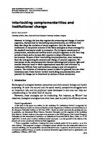
FIG. 3. Diagram illustrating how polarization charge can occur when 3 or more perpendicular 90◦ domain orientations meet. a) All domain walls are straight. polarization charge Q is localized to the 45◦ tilted 180◦ wall between domains A and C. b) Curved walls on domain C. The same polarization charge Q is now spread over the walls between B and C. c) Domains A and B move to tilt the wall between A and C transforming it into an untilted 180◦ domain wall. Polarization charge is eliminated.
22
1
(b)
2
3
C
5
F
A
+ ++ + + ++
2
C
E
G 3
B
H
4
D
(c)
B
H
4
E
G 3
B
E A
+ +
+ +
2 G
D
1
+
(a)
+
D QD
+
+
1
5
F
H
4 A
D
C
E
5
F
W 1
1
1
(e)
(f)
+
+
+
(d)
G
+
H
H
4
B
2
+
D
A
E
C
F
5
D
A
E
C
F
5
D
A
H
4 +
4
3
B
E
+ +
3
2
+
B
3
G
+ ++ + + ++
+ ++ + + ++
2
+
+ ++ + + ++
G
C F
5
FIG. 4. Schematic of domains observed in Figure 1. On application of a vertical electric field, positive polarization charge flows along the diagonal wall until it reaches domain A (a). Polarization charge is pinned by the tip of A resulting in domain curvature at the tip until the tip depins, (b) and (c). The needle domain A retracts under the field. Domain B cannot support positive polarization charge because it is energetically unfavorable (d). The polarization charge bypasses domain B where it is subsequently sequestered by domain C, (e) and (f). Domain C detaches after domain A. Although domain B has the polarization orientation as domains A and C, its switching is inhibited by its environment.
23
(a)
1
(b)
1
2
2
G
G 3
H -D QD 5 C F
A
E
H
4 + +
D
A
E
3-
B
4
E
G
C
F
B -
H
+ ++ ++ + +
B
+ +
3
D
(c)
1
2
5 D
A
E
4 5 C F
FIG. 5. The domain pattern of Figure 4a, with the same field direction, but with negative charge ripples flowing upwards (a). (b) The charge arrives at domain C first after converting part of domain H into domain F by moving the wall region 4–5 upwards. The tip region 4 of domain C develops a positive charge because part of domain C as well as part of domain H is being switched into domains E and F. Domain C acts as a sink of charge until domain C detaches, (c) whereupon charge continues towards region 3. As before, the tip of domain B does not form a point. The principal difference with Figure 4 is that here domain C detaches before domain A.
24
FIG. 6. Bright-field in-situ transmission electron micrograph of KNbO3 showing three 90◦ needle-like domains pinned at their tips by dislocations.
25
FIG. 7. (a) Diagram illustrating the local polarization charges and polarization vectors P L and P R either side of a tilted 180◦ domain wall far from the electrodes. (b) Detailed view of the polarization geometry near the tilted wall region. In zero appled field, the local polarization is tilted θ1 away from the wall. The depolarization field Ew is treated as constant out to a distance equal to half the lateral extent of the tilted wall region.
26