Apr 13, 2017 - dissipative Kerr solitons [17â21], dual-comb spectroscopy. [12, 22] and 2f â 3f self-referencing [23]. Beyond the promising applications, the ...
Efficient visible frequency comb generation via Cherenkov radiation from a Kerr microcomb Xiang Guo,1 Chang-Ling Zou,1, 2 Hojoong Jung,1 Zheng Gong,1 Alexander Bruch,1 Liang Jiang,2 and Hong X. Tang*1
arXiv:1704.04264v1 [physics.optics] 13 Apr 2017
1
Department of Electrical Engineering, Yale University, New Haven, Connecticut 06511, USA 2 Department of Applied Physics, Yale University, New Haven, Connecticut 06511, USA
Optical frequency combs enable state-of-the-art applications including frequency metrology, optical clocks, astronomical measurements and sensing. Recent demonstrations of microresonator-based Kerr frequency combs or microcombs pave the way to scalable and stable comb sources on a photonic chip. Generating microcombs in the visible wavelength range, however, has been limited by large material dispersion and optical loss. Here we demonstrate a scheme for efficiently generating visible microcomb in a high Q aluminum nitride microring resonator. Enhanced Pockels effect strongly couples infrared and visible modes into hybrid mode pairs, which participate in the Kerr microcomb generation process and lead to strong Cherenkov radiation in the visible band of an octave apart. A surprisingly high conversion efficiency of 22% is achieved from the pump laser to the visible comb. We further demonstrate a robust frequency tuning of the visible comb by more than one free spectral range and apply it to the absorption spectroscopy of a water-based dye molecule solution. Our work marks the first step towards high-efficiency visible microcomb generation and its utilization, and it also provides insights on the significance of Pockels effect and its strong coupling with Kerr nonlinearity in a single microcavity device.
I.
INTRODUCTION
The optical frequency combs are invaluable in diverse applications, including but not limited to precision metrology [1–3], optical communication [4], arbitrary waveform generation [5], microwave photonics [6, 7], astronomical measurement [8, 9] and spectroscopic sensing [10–12]. The large size and demanding cost of the mode-locked laser combs stimulate the need for a stable, low-cost and compact comb source, where the whispering gallery microresonator brings the breakthrough [13, 14]. Microresonators provide an excellent device configuration for comb generation on a chip, benefiting from the enhanced nonlinear optic effect by the high quality factors and small mode volume, as well as the engineerable dispersion by the geometry control. Over the last decade, we have witnessed the exciting progresses of microcombs, including octave comb span [15, 16], temporal dissipative Kerr solitons [17–21], dual-comb spectroscopy [12, 22] and 2f − 3f self-referencing [23]. Beyond the promising applications, the microcombs also provide a new testing bed for intriguing nonlinear physics because of its roots on generalized nonlinear Schrodinger equations, and allow for the fundamental studies of solitons, breathers, chaos, and rogue waves [24–28]. Despite the demanding need of visible combs for applications such as bio-medical imaging [29], frequency locking [30], and astronomical calibration [8, 9], demonstrating a microcomb in visible wavelength is rather challenging. The large material dispersion together with elevated optical loss in most materials appears to be the main obstacles for generating and broadening the visible microcomb. Great efforts have been devoted by the community to address these challenges. Only relatively narrow Kerr combs have been generated at the wavelength below 800 nm in polished calcium fluoride [31] and silica bubble [32] resonators, whose quality factors are challenging to achieve for typical integrated microresonators. In this article, we demonstrate a scheme for highefficiency visible microcomb generation on a chip by combining two coherent nonlinear optical processes (Pockels
and Kerr effects) in the microresonator. We realize a modified four-wave mixing process where the pump resides in the low loss infrared band but emits photons into visible band directly through the strongly coupled visible-infrared mode pairs. First, the strong second-order (Pockels effect) � optical nonlinearity χ(2) in aluminum nitride (AlN) microring [33] coherently couples the visible and infrared optical modes, which form hybrid mode pairs [34]. Mediated by these hybrid mode pairs, the visible modes participate in the four-wave mixing processes, which is stimulated by a pump laser � at infrared wavelength through Kerr nonlinearity χ(3) . This strong hybridization of χ(2) − χ(3) process enables efficient comb generation in the highly dispersive visible wavelength band. The nonlinear mode coupling between the visible and infrared optical modes leads to the observation of Cherenkov radiation in the visible comb spectrum, which is a new mechanism originated from the modified density of state by the coherent χ(2) nonlinear processes. This nonlinear-mode-coupling-induced Cherenkov radiation differentiates the current work from previous approaches of converting infrared comb to visible wavelengths by external frequency doubling [11, 35] or weak intracavity χ(2) process [36–39], behaving as the backbone for the realized high pump-to-visible comb conversion efficiency. We further show that our visible microcomb can be robustly tuned by more than one free-spectral-range through thermal tuning, a vital property for f − 2f self-referencing [40] and frequency locking to atomic transmission [30]. Lastly, we perform a proof-of-principle experiment to showcase the visible comb spectroscopy of a water-based dye molecule solution, which is not accessible by the more commonly available near-infrared comb because of the strong water absorption.
2
(a)
(b)
χ(2) & χ(3)
χ(3)
χ(2)
+
=
(c) (2)
) ,Ω 0 (2m 0
(3)
χ &χ
) ,2ω 0 Cherenkov (2m 0 Radiation
Frequency
χ(2)
) ,ω 0 (m 0
χ(3)
(
χ(3)
χ(2)
(
Orbital mode number
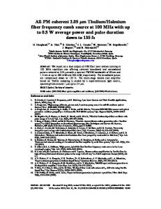
FIG. 1. AlN microring resonator for efficient comb generation and emission in visible wavelength. (a) Dual wavelength band frequency comb generation in a microring resonator. A single color pump is sent into a microring resonator with hybrid secondand third- order nonlinearity. After reaching the threshold of comb generation process, the infrared part of the comb is coupled out through the top bus waveguide while the visible part of the comb is coupled out through the bottom wrap-around waveguide. Background: false-color SEM image of the core devices. Eight (three shown in the SEM) microrings are cascaded using one set of bus waveguides. (b) The energy diagram of the χ(2) , χ(3) and the cascaded nonlinear interaction that involves the visible modes in the modified four wave mixing process. (c) The positions of the comb lines (red and blue solid circles) and their corresponding optical modes (red and blue open triangles) in the frequency-momentum space. The size of the circles represent the intensity of the comb lines. Cherenkov radiation appears in the position where the visible comb line has the same frequency as its corresponding optical mode. Inset: schematic of dual-band comb generation process in a hybrid-nonlinearity microring cavity.
II.
THEORETICAL BACKGROUND AND DEVICE DESIGN
Figure 1(a) shows a false color scanning electron microscope (SEM) image of the fabricated microring systems. We design a series (typically eight) of microrings which share the same set of coupling waveguides but have a constant frequency offset. As a result, each microring resonator can be pumped independently, which dramatically enlarges the device parameter space that we can afford for optimal device engineering within each fabrication run. The middle inset of Fig. 1(a) shows the schematic illustration of the dual-band comb generation process in the microring. The AlN microring supports high quality-factor (Q) optical modes ranging from visible (blue lines) to infrared (red lines) wavelengths. These optical modes form a variety of energy levels interconnected by second- and third- order nonlinearity, giving rise to two kinds of coherent nonlinear processes (Fig. 1(b)). First, driven by the χ(2) Pockels nonlinearity, optical modes in visible and infrared bands can be strongly coupled and form hybrid modes [34]. Here in our system the visible modes are higher-order transversemagnetic (TM) modes (TM2 ) while the infrared modes are fundamental TM modes (TM0 ). The amount of hybridization relies on the phase match condition of the χ(2) process, which can be engineered by tuning the width� of the microring [41]. Second, due to the Kerr effect χ(3) , these hybrid modes participate in the microcomb generation process [13, 17, 20, 42] and lase when the pump laser reaches a certain threshold. Therefore, the combination of strong
χ(2) and χ(3) nonlinearity of AlN allows the efficient generation of both infrared and visible combs, as shown in the inset of Fig. 1(c). To describe the cascaded coherent nonlinear process in our system, we represent the infrared and visible mode families by bosonic operator aj and bj . The corresponding mode frequencies are ωj = ω0 + d1 j + d2 j 2 /2 and Ωj = Ω0 + D1 j + D2 j 2 /2, respectively, when neglecting the higher-order dispersion. Here, the central infrared (visible) modes a0 (b0 ) has a frequency of ω0 (Ω0 ) and an orbital mode number of m0 (2m0 ). j∈ Z is the relative mode number with respect to the central modes (a0 , b0 ). d1 and D1 are the free spectral ranges, while d2 and D2 describe the group velocity dispersion of the corresponding mode families. We can see from the above expressions that the optical modes of infrared and visible wavelength are not of equal spacing in frequency domain, which is illustrated by the open triangles in Fig. 1(c). On the other hand, the frequencies of infrared and visible comb lines are of equal spacing, which can be expressed by: ωj,comb = ω0 + d1 j, Ωj,comb = 2ω0 + d1 j. The position of the comb lines are represented by the dots in Fig. 1(c). We introduce the integrated dispersion Dint , which describes the angular frequency difference between the optical modes and the corresponding comb lines. It is intuitive that when the integrated dispersion for infrared (Dint,IR = ωj − ωj,comb ) or visible (Dint,vis = Ωj − Ωj,comb ) mode approaches 0, the light generated in that mode will be enhanced by the resonance. As a result, in our system we should expect an enhanced comb generation in visible wavelength where Dint,vis ≈ 0 (as noted in Fig. 1(c)), which is referred to the Cherenkov radiation and discussed later.
3
N1 X
H =
N2 X
~∆aj a†j aj +
j=−N1
Dint/κa
j=−N2
(1)
� � P (2) where Hχ(2) = j,k,l ~gjkl aj ak b†l + a†j a†k bl is the threewave mixing interaction arising from Pockels effect of AlN (2) with coupling strength of gjkl , and Hχ(3) includes the fourwave mixing interaction (Kerr effect) inside one mode fam(2) ily or between two mode families [43]. Note that gjkl is nonzero only when j + k = l due to momentum conservation. With a pump field near a0 (with a detuning δ), the frequency detunings between the comb lines and the optical modes are ∆aj = d2 j 2 − δ and ∆bj = Ω0 + (D1 − d1 ) j + D2 j 2 − 2 (ω0 + δ). Under strong external pump, the cavity field of the pump mode (a0 )pcan be approximated by a classical coherent field a0 ≈ Np with Np for the intracavity pump photon number. We can therefore linearize the three-wave mixing interaction and obtain the dominant coherent conversion between two mode families � X (2) � † Hχ(2) ≈ ~Gj aj bj + a†j bj , (2) j (2) (2) p where Gj = g0jj Np . Despite a large difference in optical frequency, infrared (aj ) and visible (bj ) mode families are coupled through nonlinear interaction, which is essentially analogous to the linear coupling between two different spatial mode families of the same wavelength [44]. This nonlinear coupling leads to the formation of visible-infrared hybrid mode pairs, which can be described by the bosonic operators as superposition of visible and infrared modes
� i 1 h (2) a Gj aj + λ+ j − ∆j bj , NA,j i � 1 h − (2) λj − ∆bj aj + Gj bj , Bj = NB,j r� � � � Aj =
b ∆a j +∆j 2
(b)
~∆bj b†j bj
� � +Hχ(2) + Hχ(3) + ~�0 a0 + a†0 .
where λ± j =
(a) Dint/κa
We first describe how the visible and infrared optical modes can be coupled through Pockels effect. The dynamics of modes in the resonator can be described by the Hamiltonian
±
b ∆a j −∆j 2
2
(2)
+ Gj
(3)
(c)
(d)
(e)
(f)
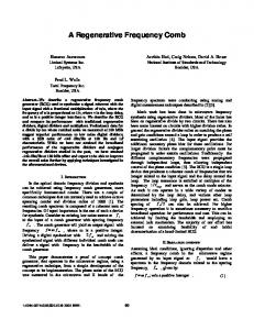
FIG. 2. Cherenkov radiation induced by nonlinear mode coupling. (a) The density of state for the infrared modes with a pump in a0 mode. Here the natural logarithm of the calculated density of state is plotted. An anomalous dispersion leads to a parabolic shape of frequency detuning between the frequency of each comb line and that of the optical modes. The dashed red line shows the frequency detuning Dint(IR) between the infrared comb lines and the corresponding optical modes. (b) The density of state for the visible modes with a pump in a0 mode. Here the natural logarithm of the calculated density of state is plotted. The dashed green line shows the frequency detuning Dint(vis) between the visible comb lines and the corresponding optical modes. The wavelength where the visible comb frequency detuning Dint(vis) approaches zero corresponds to Cherenkov radiation, leading to an enhanced emission into this mode. (c)-(d) The measured spectrum of the infrared (c) and visible (d) frequency comb. The blue arrow indicates the position of Cherenkov radiation. (e)-(f) Numerical simulation of the infrared (e) and visible (f) frequency comb. The discrepancy between (d) and (f) can be explained by a wavelengthdependent coupling efficiency from microring to wrap-around waveguide, which is not considered in simulation.
(4)
2
, NA,j and
NB,j are the normalization factors. Combing the χ(2) -induced mode coupling and the Kerr effect, an effective two-mode-family Kerr comb generation is obtained. The pump at infrared band generates emissions not only into the infrared wavelengths, but also into the visible wavelengths. For example, a possible photon emission at a frequency of ω in infrared wavelength can also be accumulated in a visible mode at a frequency of ω + ω0 + δ. As discussed above, we expect an enhanced emission where Dint,vis approaches 0, i.e. the visible comb line overlaps with its corresponding optical mode. It is convenient to quantify this on-resonance enhancement of comb generation in terms of the density of states (DOS) [43], which describes the field enhancement factor for a given optical mode and frequency detuning. By observing the DOS at the positions
where comb lines reside, we can predict the relative intensity of the generated comb lines. Figure 2(a) and (b) show the calculated DOS for infrared and visible modes, respectively. Here we are interested in the DOS along the Dint = 0 line (black dashed lines) in the figures, which corresponds to the positions where the comb lines appear. For the infrared band (Fig. 2(a)), the DOS along the black dashed line is symmetric around the pump. Dint,IR is of parabolic shape as represented by the red dashed line in Fig. 2(a). However, for the visible wavelength (Fig. 2(b)), the DOS along the black dashed line is asymmetric, showing an enhanced DOS at 725 nm where the comb line’s frequency matches the optical mode’s frequency (Dint,vis = 0). Here Dint,vis is represented by the green dashed line in Fig. 2(b). The enhanced DOS at the Dint,vis = 0 greatly boosts the comb emission due to Cherenkov radiation, similar to those observations induced by higher order dispersion [20, 45, 46]
4
(a)
(b) (i)
(i)
(ii)
(ii)
(iii)
(iii)
(iv)
(iv)
(v)
(v)
(vi)
(vi)
(vii)
(vii)
(viii)
(viii)
(ix)
(ix)
(x)
(x)
(c)
(d)
(e)
FIG. 3. Dual-band frequency comb generated by microrings with different widths. (a) Infrared combs generated by devices with a width of 1.12 µm (bottom) to 1.21 µm (top). (b) The corresponding visible combs generated by devices with a width of 1.12 µm (bottom) to 1.21 µm (top). The blue arrows show the Cherenkov radiation wavelength. (c) Cherenkov radiation wavelength for devices with different microring widths. The circles correspond to the experimental data and the solid line represents the theoretical calculations. The pentagram marks the device which is used to measure the power dependence in Fig. 4. (d) The number of infrared (red) and visible (blue) comb lines for devices with different widths. (e) The total power of the infrared (red) and visible (blue) comb lines for devices with different widths.
or linear mode coupling [44, 47].
III.
EXPERIMENTAL MEASUREMENTS A.
Dual band frequency comb
In the experiment we pump our microring with a 100 kHz repetition rate, 10 ns-long laser system (See Appendix B and supplementary section IV for more details). Figure 2(c) and (d) are the typical measurement spectra of the dualband combs. The infrared comb spectrum is relatively symmetric around the pump wavelength, as predicted by the
DOS in Fig. 2(a). For the visible combs, however, the spectrum is asymmetric and extends towards short wavelength side. The strong emission peaks near the second harmonic wavelength (777 nm) of the pump are attributed to the large intracavity photon number near pump wavelength, while the strong emissions centered around 725 nm (noted by the blue arrow in Fig. 2(d)) are attributed to the Cherenkov radiation, which is characterized by an enhanced DOS and Dint,vis = 0 as shown in Fig. 2(b). We will show later that when the large intracavity pump photon number is combined together with Cherenkov enhancement, i.e. when the Cherenkov radiation wavelength is close to the second harmonic wavelength of the pump, very efficient visible comb
5
(b) Dint/κa
(a) Dint/κa
generation can be obtained. As a further confirmation of this Cherenkov radiation mechanism, we carry out the numerical simulation of comb generation process. The numerical calculation is based on the Heisenberg equations of optical modes derived from the Hamiltonian shown in Eq. 1 [43]. Comparing the simulated results (Fig. 2(e) and (f)) with the experimental data, we find valid agreement which consolidates our analysis of the physical mechanism. The residual difference between the simulation (Fig. 2(f)) and the measured results (Fig. 2(d)) can be explained by a wavelength-dependent coupling efficiency between the microring and the visible light extraction waveguide, which increases with wavelength due to larger evanescent field but is not considered in our simulation model. The optical mode number where the Cherenkov radiation appears (jCR ) should satisfy the linear phase match condition Dint,vis (jCR ) = 0, which corresponds to q (D1 − d1 ) 1 2 jCR = − ± (D1 − d1 ) − 2D2 (Ω0 − 2ω0 ). D2 D2 (5) According to Eq. 5, the wavelength of Cherenkov radiation is related to Ω0 − 2ω0 , which is the frequency detuning between the second harmonic of the pump and its corresponding visible optical mode. To verify this relation in experiment, we change the frequency detuning Ω0 − 2ω0 by controlling the width of the microring, which is varied from 1.12 µm to 1.21 µm. Figure 3(a) and (b) show the measured dual comb spectra generated from microrings with different widths. We find that the position of the Cherenkov radiation (as noted by the blue arrows in Fig. 3(b)) in the visible comb spectrum changes consistently from shorter to longer wavelength with the increase of the microring width. Figure 3(c) shows the measured central wavelength of Cherenkov radiation (dots) against the microring width, exhibiting a good agreement with the theoretical prediction according to Eq. 5 (solid line). As easily observed from the comb spectra (Fig. 3(a)), the power, span, and the envelope shape of the infrared combs of different devices are quite similar because the dispersion at infrared wavelength is not sensitive to the widths of the microring. In contrast, those of the visible combs change drastically (Fig. 3(b)). In Fig. 3(d), the span of dual-band combs is summarized. We find that the appearance of Cherenkov radiation can help extend the span of the visible comb, which has been demonstrated in Kerr combs [20, 46]. When the Cherenkov radiation appears far-away from the second harmonic wavelength of the pump (e.g. the first and last devices in Fig. 3(b)), the generated visible comb tends to have a broader comb span and more comb lines. On the other hand, when the wavelength of Cherenkov radiation is close to the second harmonic wavelength of the pump (e.g. the 5th and 6th devices in Fig. 3(b)), there are less visible comb lines but the total power of the generated visible comb is greatly enhanced. As clearly observed in Fig. 3(e), the visible comb power (blue dots) varies more than two orders of magnitudes from 5 × 10⁻³ mW to 0.61 mW, while the power of infrared comb (red dots) keeps around 0.1 mW. It is quite counter-intuitive that the power of the generated visible comb can be almost ten times larger than that of the infrared comb. Such results cannot be explained by the simple conversion from infrared comb to
(c)
(d)
FIG. 4. Dual band comb generation efficiency under different pump powers. (a) The density of state for the infrared modes (with a pump in the a0 infrared mode) when the Cherenkov radiation is close to the second harmonic wavelength of the pump. (b) The corresponding density of state for the visible mode. (c) infrared (red) and visible (blue) comb powers under different pump powers. (d) On-chip conversion efficiency of the generated infrared (red) and visible (blue) combs. Here both the pump and the generated comb powers refer to the average powers.
the visible comb, and reaffirms the important role of the visible-infrared strong coupling in the visible comb generation process. We further investigate the dependence of comb power on the pump power, as shown in Fig. 4(c) and (d). When the Cherenkov radiation matches the second harmonic wavelength of the pump, an increase of comb powers with pump is observed in both infrared and visible bands (Fig. 4(c)). The pump-to-comb power conversion efficiency saturates at 3% for infrared combs and 22% for visible combs (Fig. 4(d)). Such high conversion efficiency can be attributed to both the large cavity photon number near the pump wavelength and the Cherenkov radiation enhancement. As can be observed in Fig. 4(b), the DOS at Dint,vis = 0 wavelength is greatly boosted, much larger than that can be observed when the Cherenkov radiation wavelength is far-away (e.g. Fig. 2(b)). Such large DOS finally enables the surprisingly high visible comb generation efficiency. The detailed comb spectra under different pump powers are shown in the supplementary section V.
B.
Thermal tuning of optical comb
The ability of continuously tuning the frequency comb is vital for applications such as precision sensing, frequency locking to atomic transition, and f −2f self-referencing. By tuning the temperature of the device, we obtain a continuously tunable visible comb by more than one free spectral range through thermo-optic effect [48], which allows for a much larger frequency tuning range than the mechanical actuation [49] or electro-optic effects [50]. Figure 5(a) and
6
(a)
(b)
(c)
(d)
FIG. 5. Wavelength tuning of both infrared and visible frequency combs. (a)-(b) The infrared frequency comb spectrum under different temperature of the device. (b) shows the zoomin of the dashed box region in (a). (c)-(d) The visible frequency comb spectrum under different temperature of the device. (d) shows the zoom-in of the dashed box region in (c).
(c) show the infrared and visible comb spectra under different temperature. The measured thermal shifting of the infrared comb lines are 2.62 GHz/K. Considering the free spectral range of 726.7 GHz, a temperature tuning range of 277.4 K is needed for shifting the infrared comb by one free spectral range. The visible comb lines, however, have a thermal shifting (5.24 GHz/K) twice as large as the infrared comb line. This doubled thermal shifting can be explained by the three-wave mixing process where two of the infrared photons combine together to generate one visible photon. The zoom in of the spectra in Fig. 5(b) and (d) clearly show that the visible comb has been tuned by one free spectral range with thermal tuning while the infrared comb is tuned by half free spectral range. C.
Visible comb spectroscopy
Spectroscopy is one of the important applications of optical frequency comb. For bio-medical sensing, which is predominantly in a water environment, visible optical combs are needed because of water’s low absorption coefficient in this wavelength range. Here we show the proof-ofprinciple experiment of frequency comb spectroscopy using our broadband, high power visible comb. To validate this method, we first apply our visible comb to measure the transmission spectrum of a thin film bandpass filter near 780 nm. By tuning the angle of the bandpass filter, the transmission band can be tuned continuously. After generating the visible comb on-chip, we send the comb through a fiber-to-fiber u-bench (Thorlabs FBC-780-APC) where the thin film filter can be inserted. The experimental setup is shown in supplementary section IV. Here the visible comb spectrum through an empty u-bench is measured as a reference, as shown by the blue line in Fig. 6(a). We then insert the thin film filter inside the u-bench with either 0◦ or 15◦ tilting, and measure the transmitted visible comb spectra afterwards. As shown by the green and red lines in Fig. 6(a), the passband of the thin film filter is tuned to shorter wavelength with an increase of tilting angle. We can extract the transmission of the bandpass filter in the position of each comb line, as plotted in Fig. 6(b) with green and red circles. To independently calibrate the sample’s absorption, we use a tunable Ti: sapphire laser (M2 Lasers
SolsTiS) to measure the transmission spectrum of the bandpass filter, as shown by the dashed lines in Fig. 6(b). A good agreement between these two methods has been observed. The visible microcomb is then used to measure the transmission spectrum of a water-solvable fluorescent dye molecule. The output of our visible comb is sent through a cuvette which contains either pure water or dye solution, and the transmitted comb spectra are measured as shown in Fig. 6(c). Comparing the comb’s spectrum after passing through the dye solution (red line in Fig. 6(c)) with the reference spectrum (blue line in Fig. 6(c)), we can clearly see the wavelength-dependent absorption induced by the fluorescent dye molecule. We plot the comb spectroscopy measurement result of this dye solution in Fig. 6(d), together with an independent measurement result using Ti: Sapphire laser (dashed line in Fig. 6(d)). A good agreement is obtained between the comb spectroscopy and the tunable Ti: sapphire laser, showing the validity of the visible comb spectroscopy in a water-based environment.
IV.
DISCUSSION AND CONCLUSION
Our experiment shows a novel scheme to generate high power microcomb in visible wavelength range, which is beneficial for realizing f − 2f self-reference on a single chip, for example by beating an octave spanning TM0 mode Kerr combs and a TM2 mode visible comb. The demonstrated thermal tuning can be an efficient way to control the carrier-envelope offset frequency. With an in situ, Cherenkov radiation enhanced frequency up-conversion process, the visible comb line power can be high enough, eliminating bulky equipment for external laser transfer and frequency conversion [23]. The ability to realize highefficiency χ(2) and χ(3) nonlinear process in a single microresonator opens the door for extending the Kerr frequency comb into both shorter and longer wavelength ranges and it is possible to realize multi-octave optical frequency comb generation from a single on-chip device. Future studies along this direction may include more coherent nonlinear effects in a single microresonator, such as third harmonic generation, Raman scattering, and electro-optical effects. Preliminary theoretical work [51] suggests the potential to realize triple-soliton states at three wavelength bands, uncovering the intriguing potential of the cascaded nonlinear process in a microcavity.
ACKNOWLEDGMENTS
H.X.T. acknowledges support from DARPA SCOUT program, an LPS/ARO grant (W911NF-14-1-0563), an AFOSR MURI grant (FA9550-15-1-0029), and a Packard Fellowship in Science and Engineering. Facilities used for device fabrication were supported by Yale SEAS cleanroom and Yale Institute for Nanoscience and Quantum Engineering. L.J. acknowledges support from the Alfred P. Sloan Foundation and Packard Foundation. X.G. thanks Chen Zhao for the discussion and help in visible comb spectroscopy measurement. The authors thank Michael Power and Dr. Michael Rooks for assistance in device fabrication.
7
(a)
(c)
(b)
(d)
15˚ tilting
0˚ tilting
FIG. 6. Comb spectroscopy in visible range. (a) Visible comb spectra with and without band pass filter. Blue line: original visible comb spectrum; green line: visible comb spectrum after 0 degree tilted thin film bandpass filter; red line: visible comb spectrum after 15 degree tilted thin film bandpass filter. (b) The measured transmission spectrum of the thin film bandpass filter using comb spectroscopy (dots) and Ti: sapphire laser (dashed lines). Inset: thin film tunable filter. (c) Visible comb spectra passing through pure water (blue) or Cy-7 fluorescent dye solution (red). (d) The measured transmission spectrum of the Cy-7 fluorescent dye. Red dot: transmission spectrum extracted from the data shown in (c); pink dot: transmission spectrum extracted from the comb data measured by a high sensitivity but low resolution optical spectrum analyzer; dashed line: transmission spectrum measured by tunable Ti: sapphire laser. Inset: the chemical formula of the used dye molecule.
APPENDIX A: DEVICE DESIGN AND FABRICATION
For efficient frequency comb generation in visible wavelength, the device geometry should be engineered to realize the anomalous dispersion for the fundamental (TM0 ) modes at the pump wavelength, as well as the phase match condition between the fundamental modes at infrared band and the high-order (TM2 ) modes at visible band. We design the microring width varying from 1.12 µm to 1.21 µm, for which parameters the anomalous dispersion is always achieved while the Cherenkov radiation wavelength is continuously tuned. For the convenience of fabricating and characterizing the microring with different geometry parameters, there are eight microring resonators in each bus waveguide sets. To avoid the overlap of the resonances for different microring resonators in the same bus waveguide sets, the radii of the cascaded microrings are offset by 9 nm, which results in an offset of resonance wavelength by 0.4 nm. As a result, the resonances of the eight microrings are well separated in frequency domain and can be selectively pumped by tuning the pump laser wavelength. There are two waveguides coupled with the microring resonator. One wrap-around waveguide tapered from 0.175 µm to 0.125 µm or from 0.15 µm to 0.1 µm is used to efficiently extract the visible light from the resonator, with a coupling gap varying from 0.3 µm to 0.5µm. The width of the other bus waveguide is fixed to be 0.8 µm with a gap
of 0.6 µm, realizing critical coupling for the pump light in infrared band. The radius of the microrings is fixed to be 30 µm. Our device is fabricated using AlN on SiO2 on silicon wafer. The nominal AlN film thickness is 1 µm, while the measured thickness is 1.055 µm. After defining the pattern with FOx 16 using electron beam lithography, the waveguide and microring resonators are dry etched using Cl2 /BCl3 /Ar chemistry, and then a 1 µm thick PECVD oxide is deposited on top of the AlN waveguide. The chip is annealed in N2 atmosphere for 2 hours at 950 ◦ C to improve the quality factors of optical modes. A critically-coupled quality factor of 1×10⁶ has been achieved in infrared band, and the visible resonance has a typical intrinsic quality factor of 1.5 × 10⁵ .
APPENDIX B: DETAILS OF MEASUREMENT PROCESS
The pump laser pulse is generated by amplifying 10 ns square pulse (duty cycle 1/1000) in two stages of EDFAs. Tunable bandpass filters are inserted after each amplification stage to remove the ASE noise. Due to the low average power of the pulses, the peak power of the optical pulse can be amplified to more than 10 W. The seeding pulse is obtained by modulating the output of a continuous-wave infrared laser (New Focus TLB-6728) with a electro-optic
8 modulator. The 10 ns pulse duration time is much longer than the cavity lifetime (< 1 ns) of our microring cavity, leading to a quasi-continuous wave pump for the optical modes. The optical comb spectra are measured by optical spectra analyzer which has a measurement span of 600 nm to 1700 nm. To avoid crosstalk in the optical spectrum analyzer, we used a long-pass (short-pass) filter to block all the
visible (infrared) light when we measure the infrared (visible) comb spectrum. Our chip sits on top of a close-loop temperature control unit (Covesion OC2) which has a thermal stability of 0.01 ◦ C and a thermal tuning range from room temperature to 200 ◦ C. The used thin film bandpass filter is 790/12 nm VersaChrome filter from Semrock and the fluorescent dye is sulfo-Cyanine7 from Lumiprobe.
[1] T. Udem, R. Holzwarth, and T. W. H¨ ansch, Optical frequency metrology, Nature 416, 233 (2002). [2] A. Schliesser, N. Picqu´e, and T. W. H¨ ansch, Mid-infrared frequency combs, Nat. Photonics 6, 440 (2012). [3] V. Torres-Company and A. M. Weiner, Optical frequency comb technology for ultra-broadband radio-frequency photonics, Laser Photon. Rev. 8, 368 (2014). [4] J. Pfeifle, V. Brasch, M. Lauermann, Y. Yu, D. Wegner, T. Herr, K. Hartinger, P. Schindler, J. Li, D. Hillerkuss, R. Schmogrow, C. Weimann, R. Holzwarth, W. Freude, J. Leuthold, T. J. Kippenberg, and C. Koos, Coherent terabit communications with microresonator Kerr frequency combs, Nature Photonics 8, 375 (2014), arXiv:1307.1037. [5] Z. Jiang, C.-B. Huang, D. E. Leaird, and A. M. Weiner, Optical arbitrary waveform processing of more than 100 spectral comb lines, Nature Photonics 1, 463 (2007). [6] A. A. Savchenkov, A. B. Matsko, V. S. Ilchenko, I. Solomatine, D. Seidel, and L. Maleki, Tunable Optical Frequency Comb with a Crystalline Whispering Gallery Mode Resonator, Physical Review Letters 101, 093902 (2008), arXiv:0804.0263. [7] W. Liang, D. Eliyahu, V. S. Ilchenko, A. A. Savchenkov, A. B. Matsko, D. Seidel, and L. Maleki, High spectral purity Kerr frequency comb radio frequency photonic oscillator, Nature Communications 6, 7957 (2015). [8] C.-h. Li, A. J. Benedick, P. Fendel, A. G. Glenday, F. X. K¨ artner, D. F. Phillips, D. Sasselov, A. Szentgyorgyi, and R. L. Walsworth, A laser frequency comb that enables radial velocity measurements with a precision of 1 cm s-1, Nature 452, 610 (2008). [9] A. Bartels, D. Heinecke, and S. a. Diddams, 10-GHz selfreferenced optical frequency comb. Science 326, 681 (2009). [10] F. Keilmann, C. Gohle, and R. Holzwarth, Time-domain mid-infrared frequency-comb spectrometer, Optics Letters 29, 1542 (2004). [11] S. Potvin and J. Genest, Dual-comb spectroscopy using frequency-doubled combs around 775 nm, Optics Express 21, 30707 (2013). [12] M.-G. Suh, Q.-F. Yang, K. Y. Yang, X. Yi, and K. J. Vahala, Microresonator soliton dual-comb spectroscopy, Science 354, 600 (2016). [13] P. Del’Haye, A. Schliesser, O. Arcizet, T. Wilken, R. Holzwarth, and T. J. Kippenberg, Optical frequency comb generation from a monolithic microresonator, Nature 450, 1214 (2007), arXiv:0708.0611. [14] T. J. Kippenberg, R. Holzwarth, and S. a. Diddams, Microresonator-based optical frequency combs. Science 332, 555 (2011). [15] P. Del’Haye, T. Herr, E. Gavartin, M. L. Gorodetsky, R. Holzwarth, and T. J. Kippenberg, Octave Spanning Tunable Frequency Comb from a Microresonator, Physical Review Letters 107, 063901 (2011), arXiv:0912.4890. [16] Y. Okawachi, K. Saha, J. S. Levy, Y. H. Wen, M. Lipson, and A. L. Gaeta, Octave-spanning frequency comb generation in a silicon nitride chip, Optics Letters 36, 3398 (2011),
arXiv:1107.5555. [17] T. Herr, V. Brasch, J. D. Jost, C. Y. Wang, N. M. Kondratiev, M. L. Gorodetsky, and T. J. Kippenberg, Temporal solitons in optical microresonators, Nature Photonics 8, 145 (2013), arXiv:1211.0733. [18] X. Xue, Y. Xuan, Y. Liu, P.-H. Wang, S. Chen, J. Wang, D. E. Leaird, M. Qi, and A. M. Weiner, Mode-locked dark pulse Kerr combs in normal-dispersion microresonators, Nature Photonics 9, 594 (2015). [19] X. Yi, Q.-F. Yang, K. Y. Yang, M.-G. Suh, and K. Vahala, Soliton frequency comb at microwave rates in a high-Q silica microresonator, Optica 2, 1078 (2015), arXiv:arXiv:1508.00170. [20] V. Brasch, M. Geiselmann, T. Herr, G. Lihachev, M. H. P. Pfeiffer, M. L. Gorodetsky, and T. J. Kippenberg, Photonic chip-based optical frequency comb using soliton Cherenkov radiation, Science 351, 357 (2016). [21] Q.-F. Yang, X. Yi, K. Y. Yang, and K. Vahala, Stokes solitons in optical microcavities, Nature Physics 1, 1 (2016), arXiv:1606.05259. [22] M. Yu, Y. Okawachi, A. G. Griffith, N. Picqu´e, M. Lipson, and A. L. Gaeta, Silicon-chip-based mid-infrared dual-comb spectroscopy, Arxiv:1610.01121 (2016), arXiv:1610.01121. [23] V. Brasch, E. Lucas, J. D. Jost, M. Geiselmann, and T. J. Kippenberg, Self-referenced photonic chip soliton Kerr frequency comb, Light: Science & Applications 6, e16202 (2016), arXiv:1605.02801. [24] A. Coillet, J. Dudley, G. Genty, L. Larger, and Y. K. Chembo, Optical rogue waves in whispering-gallerymode resonators, Physical Review A 89, 013835 (2014), arXiv:arXiv:1401.0924v1. [25] C. Godey, I. V. Balakireva, A. Coillet, and Y. K. Chembo, Stability analysis of the spatiotemporal LugiatoLefever model for Kerr optical frequency combs in the anomalous and normal dispersion regimes, Physical Review A 89, 063814 (2014). [26] C. Bao, J. A. Jaramillo-Villegas, Y. Xuan, D. E. Leaird, M. Qi, and A. M. Weiner, Observation of Fermi-PastaUlam Recurrence Induced by Breather Solitons in an Optical Microresonator, Physical Review Letters 117, 163901 (2016), arXiv:1606.06788. [27] M. Yu, J. K. Jang, Y. Okawachi, A. G. Griffith, K. Luke, S. A. Miller, X. Ji, M. Lipson, and A. L. Gaeta, Breather soliton dynamics in microresonators, Arxiv:1609.01760 (2016), arXiv:1609.01760. [28] E. Lucas, M. Karpov, H. Guo, M. Gorodetsky, and T. Kippenberg, Breathing dissipative solitons in optical microresonators, ArXiv:1611.06567 (2016), arXiv:1611.06567. [29] A. F. Fercher, W. Drexler, C. K. Hitzenberger, and T. Lasser, Optical coherence tomography-principles and applications, Reports on progress in physics 66, 239 (2003). [30] J. Vanier, Atomic clocks based on coherent population trapping: a review, Applied Physics B 81, 421 (2005). [31] A. A. Savchenkov, A. B. Matsko, W. Liang, V. S. Ilchenko, D. Seidel, and L. Maleki, Kerr combs with selectable central
9 frequency, Nature Photonics 5, 293 (2011). [32] Y. Yang, X. Jiang, S. Kasumie, G. Zhao, L. Xu, J. M. Ward, L. Yang, and S. N. Chormaic, Four-wave mixing parametric oscillation and frequency comb generation at visible wavelengths in a silica microbubble resonator, Optics Letters 41, 5266 (2016), arXiv:1606.03334. [33] X. Guo, C.-L. Zou, and H. X. Tang, Second-harmonic generation in aluminum nitride microrings with 2500%/W conversion efficiency, Optica 3, 1126 (2016). [34] X. Guo, C.-L. Zou, H. Jung, and H. X. Tang, On-Chip Strong Coupling and Efficient Frequency Conversion between Telecom and Visible Optical Modes, Physical Review Letters 117, 123902 (2016). [35] H. Jung, X. Guo, N. Zhu, S. B. Papp, S. A. Diddams, and H. X. Tang, Phase-dependent interference between frequency doubled comb lines in a χˆ(2) phase-matched aluminum nitride microring, Optics Letters 41, 3747 (2016). [36] H. Jung, R. Stoll, X. Guo, D. Fischer, and H. X. Tang, Green, red, and IR frequency comb line generation from single IR pump in AlN microring resonator, Optica 1, 396 (2014), arXiv:1410.5018. [37] S. Miller, K. Luke, Y. Okawachi, J. Cardenas, A. L. Gaeta, and M. Lipson, On-chip frequency comb generation at visible wavelengths via simultaneous second- and third-order optical nonlinearities, Optics Express 22, 26517 (2014), arXiv:arXiv:1311.1716. [38] X. Xue, F. Leo, Y. Xuan, J. A. Jaramillo-Villegas, P.-H. Wang, D. E. Leaird, M. Erkintalo, M. Qi, and A. M. Weiner, Second-harmonic assisted fourwave mixing in chip-based microresonator frequency comb generation, Light: Science & Applications (2016), 10.1038/lsa.2016.253. [39] L. Wang, L. Chang, N. Volet, M. H. P. Pfeiffer, M. Zervas, H. Guo, T. J. Kippenberg, and J. E. Bowers, Frequency comb generation in the green using silicon nitride microresonators, Laser & Photonics Reviews 10, 631 (2016). [40] P. Del’Haye, A. Coillet, T. Fortier, K. Beha, D. C. Cole, K. Y. Yang, H. Lee, K. J. Vahala, S. B. Papp, and S. A. Diddams, Phase-coherent microwave-to-optical link with a self-referenced microcomb, Nature Photonics 10, 516 (2016). [41] X. Guo, C.-l. Zou, C. Schuck, H. Jung, R. Cheng, and H. X. Tang, Parametric down-conversion photon-pair source on a nanophotonic chip, Light Sci Appl. 6, e16249 (2017), arXiv:1603.03726. [42] M. Pu, L. Ottaviano, E. Semenova, and K. Yvind, Efficient frequency comb generation in AlGaAs-on-insulator, Optica 3, 823 (2016). [43] See Supplemental Material for theoretical derivation, numerical simulation, experimental setup, and additional measurement data. [44] A. B. Matsko, W. Liang, A. A. Savchenkov, D. Eliyahu, and L. Maleki, Optical Cherenkov radiation in overmoded microresonators, Opt. Lett. 41, 2907 (2016). [45] M. Erkintalo, Y. Q. Xu, S. G. Murdoch, J. M. Dudley, and G. Genty, Cascaded Phase Matching and Nonlinear Symmetry Breaking in Fiber Frequency Combs, Physical Review Letters 109, 223904 (2012). [46] S. Coen, H. G. Randle, T. Sylvestre, and M. Erkintalo, Modeling of octave-spanning Kerr frequency combs using a generalized mean-field Lugiato-Lefever model, Optics Letters 38, 37 (2013), arXiv:1211.1697. [47] Q.-F. Yang, X. Yi, K. Y. Yang, and K. Vahala, Spatialmode-interaction-induced dispersive waves and their active tuning in microresonators, Optica 3, 1132 (2016), arXiv:1606.00954.
[48] X. Xue, Y. Xuan, C. Wang, P.-H. Wang, Y. Liu, B. Niu, D. E. Leaird, M. Qi, and A. M. Weiner, Thermal tuning of Kerr frequency combs in silicon nitride microring resonators, Optics Express 24, 687 (2016). [49] S. B. Papp, P. Del’Haye, and S. A. Diddams, Mechanical Control of a Microrod-Resonator Optical Frequency Comb, Physical Review X 3, 031003 (2013), arXiv:1205.4272 [physics.optics]. [50] H. Jung, K. Y. Fong, C. Xiong, and H. X. Tang, Electrical tuning and switching of an optical frequency comb generated in aluminum nitride microring resonators, Optics Letters 39, 84 (2014). [51] C.-l. Zou, X. Guo, L. Jiang, and H. X. Tang, The simulation of microcomb generation by multiple mode families, In preparation (2017).