REVIEW OF SCIENTIFIC INSTRUMENTS
VOLUME 69, NUMBER 7
JULY 1998
Electron paramagnetic resonance detection by time-locked subsampling James S. Hyde,a) Hassane S. Mchaourab, Theodore G. Camenisch, Joseph J. Ratke, Robert W. Cox, and W. Froncisz Biophysics Research Institute, Medical College of Wisconsin, Milwaukee, Wisconsin 53226-0509
~Received 20 March 1998; accepted for publication 29 April 1998! A detection method for electron paramagnetic resonance spectroscopy is described that permits simultaneous acquisition of multiple in- and out-of-phase harmonics of the response to magnetic-field modulation for both dispersion and absorption: ~i! conversion of the microwave carrier to an intermediate frequency ~IF! carrier; ~ii! subsampling of the IF carrier by an analog-to-digital converter four times in K IF cycles where K is an odd integer; ~iii! dividing the digital words into two streams, odd indexes in one and even in the other, followed by sign inversion of every other word in each stream; and ~iv! feeding the two streams to a computer for the digital equivalent of phase-sensitive detection ~PSD!. The system is broadbanded, in the frequency domain, with narrow banding for improved signal-to-noise ratio occurring only at the PSD step. All gains and phases are internally consistent. The method is demonstrated for a nitroxide spin label. A fundamental improvement is achieved by collecting more information than is possible using a single analog PSD. © 1998 American Institute of Physics. @S0034-6748~98!03707-1#
I. INTRODUCTION
Field modulation was introduced into continuous wave ~cw! resonance by Bloch et al.,1 who considered it as a sinusoidal time domain modulation of the resonance condition. A large modulation amplitude was used in Ref. 1 in order to display the resonance on an oscilloscope. Bloembergen et al. introduced phase-sensitive detection of the field-modulated signal2 using a low modulation amplitude. After phasesensitive detection, a signal is detected that asymptotically approaches the shape of the derivative of the resonance line as the modulation amplitude approaches zero. Analysis of field modulation in the frequency domain3 provided an alternate perspective: field modulation is like frequency modulation of the source, resulting in modulation sidebands incident on the sample. Signals are detected not only when the resonance condition of each sideband is satisfied, but also from intermodulation combinations. The use of field modulation methods to investigate nonlinear phenomena was based on a theoretical model introduced by Portis.4 Hyde extended the Portis theory and pointed out that this model permitted determination of T1 in magnetically dilute paramagnets5,6 by observing the phase and shape of the dispersion signal using suitable modulation frequencies and amplitudes. Mailer and Taylor used this method to measure T1 in cytochrome c. 7 This perspective was extended by Hyde and Dalton, who used the line shape of the first-harmonic dispersion out-of-phase signal to determine rotational correlation times of spin-labeled macromolecules in the range of 1023 – 1027 s. 8 Later, Hyde and Thomas showed that the second-harmonic absorption out-ofphase signals were also sensitive to rotational diffusion in this range.9 This particular variant is widely used today. The
use of modulation phenomena to study slow rotational diffusion is called saturation-transfer electron paramagnetic resonance ~ST-EPR!. Hyde and Thomas also pointed out that the first-harmonic out-of-phase absorption signal was a favorable T1-sensitive display.9 It was apparent to workers in this field that it would be desirable to detect in- and out-of-phase signals simultaneously at the first and second harmonics of both dispersion and absorption—requiring eight phase-sensitive detectors ~PSD! with equalized gains and well-controlled phases. However, not only were costs prohibitive, but also division of the signal into eight paths would reduce the signal-tonoise ~SNR! ratio unless a low-noise microwave amplifier ~LNA! was introduced into the signal pathway. More recently, the need for simultaneous detection of several harmonics in and out of phase for both absorption and dispersion was reinforced by the introduction of multiquantum EPR.10,11 In one form of this method, which uses no field modulation, two time-locked microwave frequencies are incident on the sample. They are closely spaced within the homogeneous linewidth. The relationship between time domain and frequency domain perspectives for this irradiation is given by the trigonometric identity: ~ 1/2! cos~ v 1D v ! t1 ~ 1/2! cos~ v 2D v ! t5cos D v t cos v t. ~1!
This irradiation pattern causes the spin system to generate a series of intermodulation sidebands at frequencies given by Eq. ~2!, where n is a positive integer,
v k 5 v 6 ~ 2n11 ! D v .
It was again apparent that broadband detection apparatus was desirable to permit simultaneous collection of all signal sidebands.
a!
Corresponding author: 8701 Watertown Plank Road, P.O. Box 26509, Milwaukee, WI 53226-0509; electronic mail:
[email protected]
0034-6748/98/69(7)/2622/7/$15.00
~2!
2622
© 1998 American Institute of Physics
Downloaded 31 Dec 2003 to 128.231.88.2. Redistribution subject to AIP license or copyright, see http://ojps.aip.org/rsio/rsicr.jsp
Hyde et al.
Rev. Sci. Instrum., Vol. 69, No. 7, July 1998
2623
FIG. 1. Signal path for TLSS detection. U(t) and V(t) stream directly to a computer for signal processing.
This paper describes the successful solution of this longstanding technical problem. We introduce the method of time-locked subsampling ~TLSS! detection. It ideally consists of the following steps: ~i! Use of a LNA to establish the noise floor of the signal x( f 0 ,t) ~see Fig. 1!. ~ii! Synthesis of a microwave local oscillator frequency ( f 0 1 f IF) that is time locked to an intermediate frequency f IF away from the signal oscillator. Time locking means that the frequencies have a fixed known temporal relation; for example, cos(2p f 0t) and cos@2p(f 01f IF)t # always start at the value 1 when t50. Time locking is necessary to preserve phase information in the signals. ~iii! Mixing the signal to an IF carrier at f IF as in conventional superheterodyne detection. ~iv! Synthesizing a new sampling frequency that is time locked to f IF at a frequency given by f s 5 f IF
4 . 2K11
~3!
Any value of K>0 is permissible; 3 was used in this article: f s 5(4/7) f IF . ~v! Analog-to-digital ~A/D! conversion at f s . As will be shown in detail, in the frequency domain the signal now resides in the bandpass from 0→ f s /2 Hz. The A/D converter must be preceded by a bandpass filter centered at f IF that matches this width. ~vi! Shuffling the digitized words ~see Fig. 1! as follows: every other odd point is sign reversed and the odd data stored in one array. Similarly, every other even point is sign reversed and the even data stored in a different location. This entire process constitutes, to this point, detection of microwave dispersion and absorption. The process in the time domain is illustrated in Fig. 2. ~vii! Feeding the two data trains, for a given static field setting, to a PC, and cross correlating with sinusoidal and cosinusoidal wave forms of as many harmonics of the modulation as desired consistent with the bandwidth. This is mathematically identical to phase-sensitive detection at all harmonics in and out of phase. This process is illustrated schematically in Fig. 3 for 14.3 kHz field modulation. In Fig. 3 the notation introduced by Thomas et al.12 is illustrated: viz. U, V for dispersion, absorption; prime to denote out of phase, and subscript to denote harmonic number. In this process all desired information has been carried in a broadband of frequencies, and narrow banding occurs at the moment of
FIG. 2. K50: Conventional baseband digital detection in the time domain; K51,2,... : TLSS detection. Digitized words obtained at the solid circles constitute a signal stream that is in quadrature with the signal stream of digitized words obtained at the open circles.
cross correlation. The analog of the time constant of the PSD is a digital smoothing filter. ~viii! Step the field, repeat, and store. TLSS detection was introduced into magnetic resonance by Stormont et al.13 in the context of magnetic resonance imaging ~MRI! and patented.14 It is used in GE Signa MRI scanners. The abstract and the patent are limited in detail and to our knowledge no full paper has appeared. The method has never been used in EPR or for the detection, in any context, to the best of our knowledge, of periodically modulated signals. For detection of such signals, there are constraints that require the modulation period to be time locked to f IF . Pohida et al. used some aspects of the method for detection of pulse EPR, but did not use subsampling.15 It is this feature that makes detection of both U and V modes using a single A/D converter and a single signal pathway possible, which is the main claim of the patent.14 The method is not well known in the conventional signal processing literature, although it has been discussed in a number of trade
FIG. 3. Computer-based signal processing of U(t) and V(t) from Fig. 1. Prime denotes out of phase with respect to the field-modulation frequency and its harmonics; subscripts define the harmonic.
Downloaded 31 Dec 2003 to 128.231.88.2. Redistribution subject to AIP license or copyright, see http://ojps.aip.org/rsio/rsicr.jsp
2624
Hyde et al.
Rev. Sci. Instrum., Vol. 69, No. 7, July 1998
journal articles in recent years,16,17 apparently because of its utility in modern digital communications. In the following sections, the theory of TLSS detection is presented, apparatus is described for TLSS detection at X band, and initial experimental results are presented. II. THEORY A. Bandpass sampling
A theoretical analysis of magnetic resonance in the presence of a time-varying magnetic field parallel to the static field, referred to as field modulation or Zeeman modulation, has been presented in the context of the Bloch equations3 as well as in the context of the density matrix formalism.18 In the frequency domain the transverse magnetization can be expanded as a Fourier series M 6 5M x 6iM y 5
(n M ~6n !e 6i~ v 6n v 0
m !t
,
~4!
where M 1 is related to the off-diagonal element of the density matrix of a single transition by M 1 5Tr ~ r ba ! ,
~5!
and the field modulation frequency f m [ v m /2p . Terms M (n) 6 are calculated from the Bloch equations. Equation ~4! transforms the differential equations into a set of 3N coupled algebraic equations. The number of harmonics in the sum is theoretically infinite. However, for the practical purposes of solving the Bloch equations or for TLSS detection, it is truncated at a certain value N above which all values of M (n) 6 are considered negligible. The choice of N is dependent on the amplitude of the modulation field H m . Thus, the signal extends symmetrically around the carrier with a bandwidth BW52N f m . In cw EPR, phase-sensitive detection with the modulation frequency acting as a reference is employed to select the harmonic to be detected. In TLSS, the frequency pattern of Eq. ~4! is downconverted to a band centered about an intermediate frequency f IF5 v IF/2p . Down conversion translates Eq. ~4! to M 6 5M x 6iM y 5
(n M ~6n !e 6i~ v
IF6n v m ! t
.
~6!
@See Fig. 4~a!.# Terms M 6 contain amplitude and phase information and are the signals to be sampled. At every harmonic, there exist four unique EPR signals:18 ~a! The in-phase dispersion:
U n 5M ~xn ! 1M ~x2n ! . ~7!
~b! The out-of-phase dispersion: ~c! The in-phase absorption:
U 8n 5M ~yn ! 2M ~y2n ! . ~8!
V n 5M ~yn ! 1M ~y2n ! . ~9!
~d! The out-of-phase absorption:
V 8n 5M ~xn ! 2M ~x2n ! . ~10!
For signals at nonzero IF, with spectral content characterized by a bandwidth BW, the general Nyquist theorem requires the sampling rate f s to be at least twice the bandwidth; thus, f s >4N f m . The effects of sampling on the frequency pattern of Eq. ~6! can be derived from application of
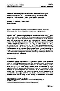
FIG. 4. Frequency domain signal processing schematics. Convolution of the patterns of harmonics ~a! with the sampling function ~b! results in repeated replication of the original signal ~c!. Since negative frequencies do not exist, the left side of ~c! folds over onto the right. Conventional baseband detection is centered at zero frequency. The frequency axes in ~a!, ~b!, and ~c! have different units for convenience of representation.
the convolution theorem. Sampling in the time domain is equivalent to multiplying the incoming signal with the function `
S s~ t ! 5
( d ~ t2kDt ! , k52`
where Dt5
1 . fs
~11!
In the frequency domain this is equivalent to convolution with the Fourier transform of S s (t), Fig. 4~b!, which results in replication of the signal as illustrated in Fig. 4~c!. The incoming signal is down-converted to produce new banded signals centered at frequencies f IF6k f s and 2 f IF6k f s . In baseband sampling, low-pass filters before the A/D input are used to ensure that no frequency component f a > f s /2 is sampled. For bandpass sampling, all sampled frequencies separated by integer multiples of f s are indistinguishable. However, aliasing occurs if components separated by noninteger multiples of f s coincide, i.e., the dotted envelopes in ~c! overlap. A hardware requirement then is to have a bandpass filter that limits the bandwidth of M 6 and also filters out the sum component resulting from frequency conversion occurring in the microwave mixer. In addition to the condition f s >4N f m , the values of f s are also constrained by the fact that f IF2k f s should be within a bandwidth of f s /2 for some integer k. 16 Thus, k is chosen such that f IF2k f s 51BW/2, or f IF2k f s 52BW/2.
~12!
An additional requirement is that the aliased frequency components from the 2 f IF6k f s band do not overlap with those of f IF6k f s . Thus, f IF2 ~ k11 ! f s 53BW/2.
~13!
The required f s is calculated as
Downloaded 31 Dec 2003 to 128.231.88.2. Redistribution subject to AIP license or copyright, see http://ojps.aip.org/rsio/rsicr.jsp
Hyde et al.
Rev. Sci. Instrum., Vol. 69, No. 7, July 1998
f s 54
f IF . 4k61
2625
~14!
Equation ~14! can be rewritten as f s 54
f IF , 2K11
~15!
for some K51,2,... . Here, K52k if the plus sign in Eq. ~14! is used, and K52k21 if the minus sign is used. For even K, the frequencies around f IF are aliased to the band (0, BW); for odd K, they are aliased to the band (2BW,0). B. Separation of U and V —the ‘‘word shuffle’’
The use of an intermediate frequency defined by Eq. ~15! allows the separation of the in- and out-of-phase components of the signal, the word shuffle. Using Eq. ~15! we find that the term e i v IFt 5 @~ 21 ! K i # m , for t5
m . fs
~16!
For odd values of K this is also equivalent to e 2i ~ p /2! f s t 5 ~ 2i ! m .
~17!
Thus, in Eq. ~6!, the term e 6i v IFt can be replaced by e 7i( p /2) f s t for t5m/ f s . The total signal at the input of the A/D converter is S5M 1 1M 2 . If S is multiplied by e i( p /2) f s t we obtain Se i ~ p /2! f s t 5
(n @ M ~1n !e in v
mt
1M ~12n ! e 2in v m t
1M ~2n ! e 2in v m t ~ 21 ! n 1M ~22n ! e in v m t ~ 21 ! m # .
If S is multiplied by e Se 2i ~ p /2! f s t 5
~18!
2i( p /2) f s t
,
(n @ M ~1n !e in v
mt
~ 21 ! m 1M ~12n ! e 2in v m t
~ 21 ! m 1M ~2n ! e 2in v m t 1M ~22n ! e in v m t # .
FIG. 5. Microwave bridge with TLSS detection. Frequencies f m , f IF , and f s are derived from synthesizers that have a common clock.
i.e., for even time points in the series, the dispersion components are detected @Eqs. ~7! and ~8!#. For the case of even K, the sign of Eq. ~20! changes. The factor (2) r in Eqs. ~20! and ~21! shows that the sign of every other sample point is inverted. Therefore, not only do U and V need to be separated but the sign has to be reversed. The output of the A/D converter is then separated into two data streams, each of which is a sum of sinusoids and cosinusoids according to Eqs. ~19! and ~20!. If the maximum number of harmonics in the sum, also defined by the bandwidth, is N, then for every modulation cycle a total of at least 4N data points have to be collected, 2N for U and 2N for V. It is advisable, however, to pick f s and f m such that f s / f m .4N. Subsequent digital cross correlation separates the harmonic constituents of each channel.
~19! Subtracting Eqs. ~18! and ~19!, we find for odd sample points (m52r11), S @~ 2r11 ! Dt #~ 21 ! r 52
F( n
@ 2 ~ M ~yn ! 1M ~y2n ! ! cos~ n v m t !
G
12 ~ M ~xn ! 2M ~x2n ! ! sin~ n v m t !# , ~20! i.e., for odd time points in the sampling series, the measured signal consists of a sum of the absorption signals, Eqs. ~9! and ~10!. For even sample points (m52r), adding Eqs. ~18! and ~19!: S ~ 2rDt !~ 21 ! r 5
(n @ 2 ~ M ~xn !1M ~x2n ! ! cos~ n v m t ! 22 ~ M ~yn ! 2M ~y2n ! ! sin~ n v m t !# ,
~21!
III. METHODS
Figure 5 illustrates a Varian E101 X-band EPR microwave bridge that has been modified for TLSS detection. Figure 5 shows inputs at the field-modulation frequency f m , the A/D sampling frequency f s , and the local oscillator ~LO! frequency f 0 1 f IF , where f IF is an intermediate frequency and f 0 is the klystron frequency. Frequencies f m , f s , f IF , and f LO are generated in the synthesizer array ~Fig. 6!. Frequencies f m , f s , and f IF are derived from a common clock and are, therefore, ‘‘time locked.’’ As is apparent from the theory section, there are a number of constraints on the choice of f m , f s , and f IF , If the A/D conversion rate and either the number of harmonics or the field-modulation frequency are fixed, other parameters are predetermined. Frequencies and other key parameters are shown in Table I for the experiments described here. A conventional 70 kHz automatic frequency control ~AFC! was used to lock the klystron frequency to the loop–
Downloaded 31 Dec 2003 to 128.231.88.2. Redistribution subject to AIP license or copyright, see http://ojps.aip.org/rsio/rsicr.jsp
2626
Hyde et al.
Rev. Sci. Instrum., Vol. 69, No. 7, July 1998
FIG. 6. Block diagram of the frequency synthesizer array.
gap resonator ~LGR! frequency ~details not shown!. A LNA with 20 dB gain ~Miteq AMF-2S-8596-4, Hauppauge, NY! was used to amplify the signal reflected from the resonator. A key aspect of the TLSS concept is the requirement to raise the noise floor above that of the detection system. See Ref. 19 for a discussion of noise considerations with LNAs in a context of EPR spectroscopy. It was decided to stream all data directly into the PC memory in order to preserve maximum flexibility in signal processing including the word shuffle and cross correlation. The A/D card ~WIN-30PGL, UEI, Watertown, MA! is specified at 1 MHz, 12 bit, with streaming capability to 1 MHz. We were unable to achieve this rate of streaming, apparently because of our requirement to use an external rather than internal clock to generate f s . In our hands, the sampling limit was approximately 350 kHz and it was decided eventually to digitize at 286 kHz. This unanticipated technical problem was encountered after the bandpass filter centered at the IF ~500.5 kHz!, Fig. 5, had been designed. As a consequence, it has a bandwidth that is twice the theoretically desirable width of 143 kHz, which results in aliasing of noise
and can be expected to degrade the performance by about 3 dB. The LGR ~Fig. 5! is of the two-loop–one-gap type.20 The effective sample volume is 1 ml. The resonator efficiency parameter L ~Ref. 21! is about 6. See Ref. 22 for a review of LGRs. Generation of the local oscillator frequency ~Fig. 6! used the technology that was developed earlier for multiquantum EPR.23 The HP 3326A synthesizer ~Hewlett–Packard, Palo Alto, CA! provides two quadrature outputs that drive the IF ports of a single sideband modulator ~SSM! ~Anaren 90338DC, East Syracuse, NY!. The voltage levels, relative phase shift, and dc offsets were adjusted for minimal carrier leakage ~at f 0 ! and spurious sideband generation using a HP8564E spectrum analyzer. A microwave power amplifier ~Miteq AMF-3B-8596-20P! with a gain of 20 dB resulted in a LO output level of 110 dBm. This output drives a double balanced mixer ~Watkins–Johnson WJ-M80C, Palo Alto; CA!. This mixer has a 0 dBm compression point, which is desirable when using a LNA. However, 3 dB was sacrificed by the use of this type of mixer; an image-reject mixer is desirable. The two IF amplifiers following the mixer have gains of 28 and 20 dB, respectively. In a typical EPR experiment, the field was scanned in 4 min with data streamed directly to disk at a rate of 286 000 points or 572 000 bytes per second, resulting in a 137 Mbyte binary data file corresponding to over 68 million data points. The field was swept linearly, and this file was divided into 1024 blocks corresponding to 1024 field positions. Each block, consisting of 66 960 points, was divided into six subblocks of 11 160 data points and these six sub-blocks were averaged. At this stage in the signal processing, the word shuffle process was carried out as described previously, resulting in U- and V-mode signals. Cross correlation was accomplished by multiplying the U and V arrays by computergenerated sines and cosines at n f m where n varied from 1 to 4 and the field modulation frequency f m was 14.3 kHz. The resulting numbers were stored, and this process repeated 1024 times to generate spectra. It was found under the nonsaturating conditions used in the present experiment that outof-phase signals with respect to the field modulation were of negligible intensity, and therefore, phases of detected harmonics were rotated by software for maximum intensity. Uand V-mode phases were subsequently rotated by software for line shapes of the required symmetry, i.e., even and odd. Representative spectra obtained by this process are shown in Fig. 7. In principle, results should not be dependent on the length of the six sub-blocks. A different number of subblocks with corresponding different lengths should yield the same final result, which was verified experimentally.
TABLE I. Frequencies. f IF5500.5 kHz ~the intermediate frequency! f s 5286 kHz ~the sampling frequency! f m 514.3 kHz ~the field-modulation frequency! f 0 58.9 GHz ~the microwave frequency! BW5143 kHz ~filter bandwidth! f s / f IF54/7 ~the subsampling ratio! f s / f m 520 ~10 samples in U and 10 in V!
IV. RESULTS
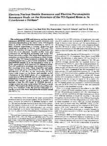
Figure 7 shows eight spin-label spectra that were acquired simultaneously in a single sweep of the magnetic field using TLSS detection: dispersion and absorption, first four harmonics in phase. A field-modulation amplitude of 1.5 G at 14.3 kHz was used along with an estimated microwave field intensity at the sample in the rotating frame of 0.2 G.
Downloaded 31 Dec 2003 to 128.231.88.2. Redistribution subject to AIP license or copyright, see http://ojps.aip.org/rsio/rsicr.jsp
Hyde et al.
Rev. Sci. Instrum., Vol. 69, No. 7, July 1998
FIG. 7. Example of eight spectra of a nitroxide radical spin label produced using TLSS detection in a single sweep of the magnetic field. The notation is defined in Fig. 3.
The incident microwave power on the LGR was 1 mW. The peak-to-peak linewidth for the sample ~1024 M TEMPO in H2O at room temperature! using a low-field-modulation amplitude is 1.2 G. Under conditions used to obtain Fig. 7, the modulation amplitude was close to the value that yields the largest possible first-harmonic signals, V 1 ,U 1 . The noise is about the same for both dispersion and absorption, and was independent of incident microwave power under the conditions used to obtain Fig. 7. The limiting noise source has not been firmly established, but noise appears to be determined by the noise figure of the low-noise microwave amplifier ~see Fig. 5!. It was experimentally verified that the noise in Fig. 7 is 3 dB higher than would be the case if an image-reject mixer had been employed to down-convert to the intermediate frequency. Mixers of this type are commercially available. At higher incident power, for example, 10 mW, microwave phase noise dominates in both U- and V-mode displays. A low-noise Gunn diode oscillator of the type described in Ref. 24 could, in principle, be used to reduce the phase noise by about 20 dB compared with the klystron used here. The overall SNR compared with conventional homodyne detection using 14.3 kHz field-modulation frequency is about the same, extrapolated to estimates of the same effective integrating time constants. However, more detailed analysis is appropriate since the effective filters in the two detection processes do not have the same characteristics in the frequency domain. When the field modulation amplitude was increased, the amplitude of the higher harmonics increased, as expected. The individual displays in Fig. 7 can be converted from even to odd symmetry, or vice versa, by a Hilbert transform without changing the noise amplitude. The symmetry can also be changed by transformations that have filtering characteristics including integration, differentiation, and pseudomodulation.25 Signals can be combined for improved resolution25 or improved SNR. As expected, noise in the eight spectra is incoherent. The condition f s >4N f m ~see the theory section! was experimentally investigated. In the present experiment, ten points are digitized for each field-modulation cycle, limiting the number of harmonics that can be detected without alias-
2627
ing to four. The field-modulation amplitude was increased in order to increase the intensity of higher harmonics. Aliasing of higher harmonics was indeed observed, which indicates the importance of the bandpass filter before the A/D converter ~see Fig. 5!. A further experimental check of aliasing was carried out by reducing the field-modulation frequency to 4.5 kHz such that 64 points were digitized for each fieldmodulation cycle. As expected, aliasing was not observed. An unexpected but understandable phase anomaly was observed during the rotation by software that was carried out in order to obtain pure dispersion and absorption signals. Since the dispersion data stream is shifted in time from the absorption data streams by one digitization period ~i.e., 1/f s 53.5 m s!, field-modulation phases differ by 2 p n f m / f s rad/s, which is 18° for the signal at the field-modulation frequency in the present experiment comparing dispersion with absorption. In conventional EPR spectrometers, the AFC system is used to make the instrument sensitive to small changes in either the real or imaginary component of the microwave reflection coefficient of the resonator. See, for example, Ref. 26. The absorption and dispersion signals are in phase with respect to these real and imaginary reflection coefficients, respectively. It is possible, in principle, to use the same strategy in TLSS detection. In the experiment described here, a conventional 70 kHz frequency-modulation AFC was used, locking the klystron to the resonant frequency of the LGR. We attempted to use the 70 kHz signal in the TLSS signal channel to set the phase for detection of either the U or V modes, but were unsuccessful. However, by introducing an additional frequency modulation at 20 kHz, it was possible to use the resulting signal as seen in the TLSS signal channel to set the U and V phases precisely. It seems certain that use of a higher f s will permit setting of phases using the conventional 70 kHz AFC system. It appears quite feasible for the entire AFC system to be based on TLSS detection. V. DISCUSSION
The goal of the work described in this paper was to establish the principles of TLSS detection of EPR signals produced by field modulation and to demonstrate initial experimental results. The choice of field-modulation frequency, 14.3 kHz, was based solely on the specifications of an A/D converter that happened to be on hand. The intent of the paper was to describe experiments designed to establish the feasibility for future development of TLSS detection using 100 kHz field modulation. In conventional EPR spectrometers, the data are in a very broad bandwidth at the microwave detector. The bandwidth is narrowed to about 5 kHz in the input amplification stage of the 100 kHz PSD, and is narrowed again to, typically, 1 Hz by the integrating time constant of the PSD. The reason for the 5 kHz filter was a concern about the nonlinear response of the final amplifiers to the broad spectrum of noise from the microwave detector. This engineering concern has never, however, been rigorously investigated. The technological risk of TLSS detection, which is an intrinsically broadband method, was that it would be subject to nonlinearities that would convert input noise to the frequencies
Downloaded 31 Dec 2003 to 128.231.88.2. Redistribution subject to AIP license or copyright, see http://ojps.aip.org/rsio/rsicr.jsp
2628
Hyde et al.
Rev. Sci. Instrum., Vol. 69, No. 7, July 1998
of interest. Thus far, no problems of this nature have been found. An additional technological risk lay in introduction of noise by the various frequency synthesizers. Synthesizers have poor noise specifications relative to high-quality fundamental oscillators. The strategy was to use sufficient microwave amplification prior to IF conversion that the noise floor would be well above any noise introduced by the IF synthesizer, the microwave mixer, the synthesizer that provides the A/D conversion rate, or the A/D converter itself. This strategy was in general successful, but a careful engineering study of noise introduced at each of these stages in the signal channel path is appropriate as the next phase in development of TLSS detection for EPR usage. Still another issue with respect to noise is that TLSS detection is effectively a modern version of superheterodyne detection, which is known to be sensitive to microwave phase noise. The gain of the LNA and the performance of the IF mixer determine the sensitivity to phase noise of the microwave source. The LGR used in the experiments described here decreases the overall sensitivity to phase noise relative to use of a conventional cavity resonator, and use of a LNA increases the sensitivity because of its improved noise figure. On balance, the klystron was not a limiting source of noise in the experiments described here where the incident power was 1 mW. The amplitude of the IF carrier depends on the mismatch of the cavity resonator. This level is critical in at least three respects: ~i! over ranging of the A/D converter can occur; ~ii! the IF level affects the sensitivity to microwave phase noise; and ~iii! the IF level serves to dither the information of interest across the quantitization levels of the A/D converter. An A/D converter with greater resolution than used here, which was 12 bits, is desirable and we anticipate using a 16 bit A/D converter in the future. For experiments described here, the field was swept continuously and data were streamed directly into a PC and digitally filtered in the temporal dimension. Ideally, the field would be stepped and acquisition of a data set would occur within the field interval before stepping to the next field point. No filtering in the field domain was employed to produce Fig. 7, but that could have been done. Complete independence of filtering in time and in field exists in TLSS detection. This is unlike the conventional analog experiment where the field is swept continuously and a 12 dB/octave analog filter is employed that combines filtering in time and in field. An interesting application of independent temporal and field filtering would be cross correlation with the fieldmodulation frequency in the time domain and cross correlation with a known spectrum in the field domain for quantitative determination of the amount of the known species present. Other advantages of TLSS detection are that the data can readily be inspected for abnormal spikes or environmental interference that could be specifically removed before filtering, and that filtering can be optimized after acquisition rather than by estimation of filter settings prior to acquisition. TLSS detection is used routinely in MRI scanners made by GE Medical Systems in a signal processing environment
that is similar to that of EPR. It is thus established that TLSS detection is a commercially reliable method. We have endeavored to be conservative in this discussion by objectively pointing out various possible problems. Nevertheless, we are convinced that TLSS detection is, indeed, the modern digital approach to EPR spectroscopy and that it will become widely used. The principal advantages of TLSS detection are ~i! improved filtering, ~ii! collection of dispersion and absorption simultaneously, and ~iii! collection of fundamental as well as harmonic responses to field modulation. Fundamentally, these three advantages individually and in concert increase the SNR in the linear ~low microwave power! regime. At higher microwave power, the response in and out of phase at the various harmonics for both dispersion and absorption with consistent phases and amplitudes constitute collection of information that reflects the nonlinear response of the spin system. ACKNOWLEDGMENTS
This work was supported by Grant Nos. GM22923 GM27665 and RR01008 from the National Institutes of Health. F. Bloch, W. W. Hansen, and M. Packard, Phys. Rev. 70, 474 ~1946!. N. Bloembergen, E. M. Purcell, and R. V. Pound, Phys. Rev. 73, 679 ~1948!. 3 W. A. Anderson, Phys. Rev. 102, 151 ~1956!, see the appendix. 4 A. M. Portis, Phys. Rev. 91, 1071 ~1953!. 5 J. S. Hyde, Phys. Rev. 119, 1483 ~1960!. 6 J. S. Hyde, Phys. Rev. 119, 1492 ~1960!. 7 C. Mailer and C. P. S. Taylor, Biochim. Biophys. Acta 322, 195 ~1973!. 8 J. S. Hyde and L. Dalton, Chem. Phys. Lett. 16, 568 ~1972!. 9 J. S. Hyde and D. D. Thomas, Ann. ~N.Y.! Acad. Sci. 222, 680 ~1973!. 10 P. B. Sczaniecki, J. S. Hyde, and W. Froncisz, J. Chem. Phys. 93, 3891 ~1990!. 11 H. S. Mchaourab and J. S. Hyde, J. Chem. Phys. 98, 1786 ~1993!. 12 D. D. Thomas, L. R. Dalton, and J. S. Hyde, J. Chem. Phys. 65, 3006 ~1976!. 13 R. S. Stormont, J. P. Noon, N. J. Pelc, N. R. Hattes, M. D. Anas, R. H. Horwarth, and R. Glusick, in SMR Book of Abstracts, Vol. 1, 8th Annual Meeting, Amsterdam, 1989 ~Society of Magnetic Resonance in Medicine, Berkeley, CA, 1989!, p. 962. 14 R. S. Stormont, M. C. Anas, N. J. Pelc, U.S. Patent No. 4,992,736, Serial No. 389456, issued February 12, 1991. 15 T. J. Pohida, H. A. Fredrickson, R. G. Tschudin, J. F. Fessler, M. C. Krishna, J. Bourg, F. Harrington, and S. Subramanian, Rev. Sci. Instrum. 65, 2500 ~1994!. 16 M. L. Schiff, Pers. Eng. Aug, 42 ~1995!. 17 C. Olmstead and M. Petrowski, RF Design Sept, 30 ~1994!. 18 L. A. Dalton and L. R. Dalton, in Multiple Electron Resonance Spectroscopy, edited by M. M. Dorio and J. H. Freed ~Plenum, New York, 1979!, pp. 169–228. 19 J. S. Hyde, M. E. Newton, R. A. Strangeway, T. G. Camenisch, and W. Froncisz, Rev. Sci. Instrum. 62, 2969 ~1991!. 20 W. L. Hubbell, W. Froncisz, and J. S. Hyde, Rev. Sci. Instrum. 58, 1879 ~1987!. 21 W. Froncisz and J. S. Hyde, J. Magn. Reson. 47, 515 ~1982!. 22 J. S. Hyde and W. Froncisz, in Advanced EPR: Applications in Biology and Biochemistry, edited by A. J. Hoff ~Elsevier, Amsterdam, 1989!, pp. 277–306. 23 P. B. Sczaniecki, J. S. Hyde, and W. Froncisz, J. Chem. Phys. 94, 5907 ~1991!. 24 T. Oles, R. A. Strangeway, J. Luglio, W. Froncisz, and J. S. Hyde, Rev. Sci. Instrum. 63, 4010 ~1992!. 25 J. S. Hyde, A. Jesmanowicz, J. J. Ratke, and W. E. Antholine, J. Magn. Reson. 96, 1 ~1992!. 26 J. S. Hyde and J. Gajdzinski, Rev. Sci. Instrum. 59, 1352 ~1988!. 1 2
Downloaded 31 Dec 2003 to 128.231.88.2. Redistribution subject to AIP license or copyright, see http://ojps.aip.org/rsio/rsicr.jsp