Embedded cluster-based architecture with high level support - presenting the. HC-MPSoC. Felipe G. MagalhËaes, Sérgio J. Filho, Oliver Longhi, Fabiano Hessel.
Embedded cluster-based architecture with high level support - presenting the HC-MPSoC Felipe G. Magalh˜aes, S´ergio J. Filho, Oliver Longhi, Fabiano Hessel Faculty of Informatics – PUCRS – Av. Ipiranga 6681, Porto Alegre, Brazil E-mail: {felipe.magalhaes, sergio.johann, oliver.longhi}@acad.pucrs.br, {fabiano.hessel}@pucrs.br Abstract—Multiprocessor System-on-Chip (MPSoC) can be found in almost every market branch and its design typically presents several restrictions such as chip area and energy consumption. State-of-art MPSoCs uses networks-on-chip as the primary communication infrastructure and the tendency is that NoC-based systems will still be used for a long time, thanks to a greater design flexibility and also a high communication bandwidth and parallelism. However, such systems also have certain usage restrictions, such as the location of the tasks that compose the application. Mapping and partitioning techniques seek to solve this problem or at least reduce it to a non critical point by diving tasks along the architecture but are not always completely successful. In this context, cluster-based architectures emerges as a viable alternative to MPSoCs. This type of system typically has a hybrid architecture on its constitution, using more than one communication infrastructure, thus being able to group elements by affinity and still use high-speed communication channels, such as NoCs. In this way, the presented work introduces the HC-MPSoC, an architecture for cluster-based intrachip systems, which uses buses and a NoC in a joint way, forming groups of elements independently distributed throughout the platform. The extensions made on the HellfireOS in order to execute it over the hybrid architecture are also presented. All HC-MPSoC modules as well as the HellfireOS modules and the results obtained using the platform are presented along the text. Keywords—MPSoC, NoC, Cluster, HellfireOS I. I NTRODUCTION Embedded systems present a rising number of features, leading to a significant growth in the applications’ design complexity. Also, systems have had their implementation based on multiple processing elements integrated on the same die, running at a lower clock frequency, due to energy consumption constraints [1]. Such integrated system is called Multiprocessor System-on-chip (MPSoC). Since the introduction of MPSoCs one of the design main concerns lies in how the communication between internal components is performed. Bus-based systems presents a well known solution, with a reasonable bandwidth and great ease of implementation, but as the internal number of components rises, buses become less likely to be used thanks to the growing design complexity [2]. Still, on traditional bus-based systems the communication can become a bottleneck in the system performance [3] which can compromise it’s operation. To solve this issue one of the most popular solutions is to use a Network-on-chip (NoC). NoC-based systems tend to provide a better communication c 978-1-4799-6851-0/14/$31.00 2014 IEEE
100
performance [4], where the communication management is performed by routers that forward packets over the network. Each network node consists of a router and a component attached to it which could be, for example, a processor or a memory. Besides the gain in the communication capability, NoCs usually have an improved energy reliability and efficiency and a high re-usability level [5]. Moreover, even NoC-based systems can present situations where their usage is not the most indicated, eg in situations where applications’ tasks are located far from each other, which increases the communication overhead thanks to the tasks dependencies. Another important drawback is the fact that the NoC routers’ physical implementation is more expensive in terms of chip area when compared to a bus, for example. Besides the architectural concern the use of multiple processing elements in a single chip introduces new challenges, like the system programmability, specially when it counts with dynamic features and real-time constraints. One way to deal with this factor is to reduce the effort required to build applications for MPSoCs. Real-time operating systems (RTOSs) offer more standard interfaces so developers can use or at least have easier access to the processing power available on hardware. As the computing power offered by new MPSoCs raises, applications and features can be included at run-time. Therefore, this work presents the Hellfire cluster-based MPSoC (HC-MPSoC), an architecture for intrachip systems that uses, jointly, buses and a NoC. This architecture was designed in such a way so it gets to use the benefits from both medias, the low-cost usage presented by buses coupled with the NoC’s greater communication capability. Thus, the designer has a greater possibilities range to map the system elements over the architecture. This way, IPs can be grouped into a cluster and communicate through a single bus, or, for situations where the communication is a critical point of the application, the designer can allocate these IPs directly to the NoC routers and utilize its high communication capacity. This configuration freedom opens great design possibilities that enrich the design space exploration. Also, along with the HC-MPSoC and its modules’ introduction, this paper presents the extensions made on HellfireOS (HFOS) [6] in order to port it to the platform. The HFOS has a well defined programming model for multiprocessed systems, which facilitates the application’s development for parallel processing architectures, such as the HC-MPSoC. The communication primitives used to exchange messages between IPs and clusters will be presented as well as the results in terms of the HC-MPSoC’s communication capability. The remainder of the paper is organized as it follows. Sec-
tion 2 shows some related work. Section 3 presents the Hellfire System, used as the base architecture in this work. Following, the description of the developed architecture is presented in Section 4. Results are presented in Section 5 and, finally, Section 6 concludes the paper besides presenting some future work. II. R ELATED W ORK This section presents the related works on cluster-based embedded architectures. An analysis of each work and then a comparison of the methodologies adopted by the authors will be shown. Despite many researches have some characteristics that could go into this comparison, only intrachip systems were taken into account. Luo-feng [7] presents a platform composed of 17 NiosII processors [8] grouped into four groups of four processors each, plus a central processor that controls the whole system, dividing tasks among groups. Each group is connected via one shared memory and each processor has a local memory for its own tasks. To perform the communication between clusters and the central processor an irregular NoC was used. The input and output control as well as the access to peripherals are all held in the master processor, centralizing the MPSoC control at a single point. The main differences between the work presented by Luo-feng and the work presented here lies in the fact that the architecture introduced here is more easily configurable as it uses a customizable NoC. Another important difference is the fact that, despite the centralized control presented by Luo-feng, this work employs a full parallel approach. At last the fact that no programming model to be used over the platform or no highlevel support was introduced by Luo-feng must be pointed. Jin [9] introduced a cluster-based system formed by ARM processors grouped in ’n’ clusters of variable size which communicate through an AMBA-AHB bus [10]. The communication between clusters is performed by a NoC with a cluster on each router. The structure introduced by Jin seems to be very promising, however, unlike the work suggested here, no highlevel support is presented which increases the project complexity. An architecture using a NoC as the communication infrastructure between clusters and a simple bus to communicate internal elements on each cluster is presented in [11] and named P2012. In this model each node is composed by IPs that may be hardware or soft cores plus two modules to communicate with the NoC router. The P2012 is an easily configurable platform that is scalable for a large amount of cores, however, unlike the work suggested here, the P2012 platform uses proprietary IP cores, which can hinder their use and integration with projects that do not use such IPs. Another important issue lies in the fact that no programming model is presented. This fact may compromise the usability of the platform or, at least, make the applications’ design harder. Seifi [12] presented a cluster-based system using a single NoC with modified routers. Unlike all previous works presented here the work introduced in [12] does not use buses to communicate the inner cores of their clusters, which are directly connected to the NoC router. In order to allow such thing the NoC routers were changed to include three more local ports. An important
101
limitation of this architecture is its scalability as the number of IPs on each cluster is limited to four. Still, there is no high-level support to program the system. The work presented in [13] introduces a different approach for embedded cluster-based system. While all presented solutions uses physical hardware implementations, the work presented in [13] uses virtualization techniques to expand the MPSoC capability, running ’n’ virtual processors on each physical unit. This solution uses MIPS processors [14] and a central NoC to perform the communication between physical cores. An important limitation of this architecture lies in the fact that the use of virtual processors can imply on a high overhead as well as the fact that the choice of processors to be used used are limited to the ones that are already available. Tudruj [15] presents a model of dynamic clusters where the message exchange is performed using local memories. The internal modules of each cluster are interconnected with a bus and the clusters are connected through a point-to-point connection. The main limitation of this architecture is its scalability, due the fact that a point-to-point connection is used. While point-topoint architectures provides a great communication throughput, their usage is limited to a few nodes due to the increased design complexity. A cluster-based architecture using internal buses and an external NoC is presented by Chen [16]. At each cluster three ARM processors are connected to a communication interface with a NoC router through a simple bus. An important difference of the work presented by Chen and the work proposed here is the fact that the number of internal processors in each node is always set in three, besides that no high-level support is presented. A spotty architecture is presented by Leng [17]. This architecture is formed by routers distributed in a non-linear way and on each router, a cluster node with ’n’ IP cores and a simple bus is attached. No comments were made regarding which IP cores were used in the architecture, unlike the work presented here, that uses Plasma cores. Another important consideration is the fact that an irregular architecture was used, which can result on a greater manufacture effort. The Table I presents a comparison between the previous works and the proposed one, where five characteristics were used for comparison, as follows: • A - Internal communication infrastructure: corresponds to the means of communication used by the internal nodes on each cluster; • B - Communication infrastructure between clusters: media used to realize the communication between different clusters; • C - High-Level support: points the presence, or not, of any high-level development support, like an operating system; • D - System Control: indicates whether there is a node in the system that performs the division of tasks as well as controls the data input and output; • E - IP Used: IP module used as processing unit. G-IP defines a generic core, when none is explicitly pointed. By the table it is possible to observe that buses’ usage for the inner communication on clusters is a major trend. Another common thread in most cases, with just one exception, is the adoption of a NoC as the central communication media.
TABLE I W ORKS C OMPARISON
/ A B C D E
[7] Bus NoC No Centralized NiosII
[9] Bus NoC No Local ARM
[11] Bus NoC No Local G-IP
[12] Router NoC No Local STxP70
[13] Virtual NoC Yes Local Plasma
An important feature to point out is the fact that only one of the previous works cited have some kind of high level support or programming model presented. This kind of support eases the applications’ development on the platform but are not always provided, a fact that the work presented here suppresses as it provides an API to be used over the platform. III. H ELLFIRE S YSTEM Despite the fact that the time for embedded systems’ design is dwindling in order to don’t lose the time-to-market, the number of constraints that involves its project are increasing significantly. To aid its development and also decrease its design time different platforms like [18] and [19] offer features such as simulation and debugging tools that streamline this process. Another example of design aid tool is the Hellfire Framework [20], which was used as the base platform in this work. The Hellfire System is formed by four main modules: • HellfireOS: embedded real time operating system; • Hardware: composed by ’n’ Plasma processors and a communication infrastructure; • Simulator: emulates all hardware functionalities; • Web-Framework: integrates onto a web interface the software and a platform model. As the focus of this work is only on the architectural level and its support, exclusively the HellfireOS will be introduced. A. HellfireOS The HellfireOS is a real-time operating system (RTOS) developed intending to ensure maximum flexibility on its configuration and allow a high level platform customization. In order to allow such features, the HFOS was implemented in a modular way, where each module corresponds to some specific functionality. The HFOS is organized in layers and all hardware-specific functions are defined in the first layer, known as HAL (Hardware Abstraction Layer). The uKernel lies just above it and the communication, migration, memory management and mutual exclusion drivers, as well as the API are placed over the uKernel layer. The user applications belong to the top layer. Due to its modular implementation, the HellfireOS is easily portable to others architectures, requiring only the rewrite of hardware-dependent functions, implemented in the HAL. In order to decrease the kernel final size, allowing HFOS to be used even in architectures with severe memory limitations, parameters such as maximum number of user tasks, stack and heap size and drivers are configurable. The users’ applications
102
[15] Bus P2P No Local G-IP
[16] Bus NoC No Local ARM
[17] Bus NoC No Local G-IP
HC-MPSoC Bus NoC Yes Local Plasma
are written using the C programming language and the HellfireOS API. Another configurable parameter is the the activation bit used by the timing register, which determines the system tick size. The tick size corresponds to the minimum periodic timing unit of the system. This unit varies from 0.32ms to 83.88ms1 and the relation between the processor clock frequency rate and the bit activation bit is ruled by the following formula: tick = f2req . In order to describe an application, a defined model is used, where the application is represented as one or more tasks that execute in the processing elements. Each one of the tasks is characterized with its own parameters, along with the code and data used to implement its functionality. Thus, a task is defined as an n-uple Ti =< idi , uidi , pi , ei , di , lci , pwri , cdi , dti >, where: idi represents the task local identification and uidi its unique identification in the system, pi stands for period of task i; ei represents the task execution time or capacity; di is its deadline; lci stands for a communication related list; pwri represents the task energy requirements; and finally, cdi , dti represent the task code and data segments, respectively. Here, pi , ei and di parameters are specific to a given real-time scheduling policy and must be informed in abstract time units. pwri , cdi and dti require further characterization, as they depend on the technology, the algorithm and the compiler chosen. Each task execute according to this task model2 , and is mapped onto a single processing element, where it may share processing time with other tasks. Still, communication between tasks is represented by the tuple cij = < tj , ωij >, where tj is the target task and ωij the data content for this communication. As the total communication data generated by a single task can be composed by several communication interactions, the total communication is reprePn−1 sented by lci = i=0 ωij , where n is the number of interactions.
The Figure 1 shows an example of a task description and its initialization on HFOS. On the figure it is possible to see a task named my task declared with some random and no relevant functionalities. Just below the task description, its initialization is performed using some parameters, like period and capacity.
1 the tick size used is a decision made at design time and is a trade off between tasks’ context switch and its response time 2 The simple task model assumes that: (i) all tasks are periodic, (ii) the relative deadline of a given task is equal to its period and (iii) all tasks are independent, so there is no precedence.
A simple bus was implemented to serve as the internal communication infrastructure between elements on each cluster. This bus consists of a shared via controlled by an arbiter that uses a round-robin algorithm to decide which port will have access to the bus. Figure 3 shows the basic structure of the bus where four IPs are connected to the bus via wrappers, identified in the figure as W. These wrappers are responsible for protocol conversions between the IP module and the bus, performed in a pipeline way, avoiding performance loss during the conversion. The wrapper is also responsible for requesting access to the bus thought the arbiter, thus, the arbiter can manage the access to the bus and the input and output units, identified in the figure by I/O.
Fig. 1. Task Example
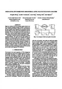
IV. D EVELOPED W ORK This Section presents the developed work, where the hardware modules that composes the HC-MPSoC are presented. The new HFOS communication driver will also be introduced, with the new available primitives to communicate clusters. The modules introduction and the new driver will be presented in two sub-sections apart, being the hardware modules presented on the Sub-section 4-A and the new driver introduced on the subSection 4-B. A. HC-MPSoC Tasks division among different processors for increased system performance is already a common practice in embedded systems, but the communication can be a bottleneck, by not presenting a great scalability thus limiting the number of processors that can be used (bus) or presenting situations where the mapping of tasks on the MPSoC can result in prohibitive messages exchange times (NoC). The developed platform attempts to minimize those issues by using a hybrid approach consisting of a NoC and various buses. Figure 2 presents an overview of the developed platform. It is possible to observe the presence of a centralized NoC, responsible for the exchange of messages between clusters and, on each cluster a sub-system formed by a single bus and ’n’ indoor units. It is noteworthy that each NoC router can be attached to a cluster composed by, at most, eight IPs or directly to a single IP module. This limitation on the number of internal cluster components is justified by the well known fact that buses do not scale well.
Fig. 2. Cluster platform overview
103
Fig. 3. Bus overview
For our NoC implementation we use HERMES NoC [21], which implements a mash topology and is composed by routers, buffers and controllers of routers information (switch control). Still, the internal queue scheduling uses the Priority Round Robin algorithm. The packet routing algorithm that is used is the XY [22] and the packet flow protocol is handshake. In order to communicate the inner cores of the cluster with the NoC router a wrapper was developed and named Cluster Interface (CI). The CI consists of two queues used to temporary store the data that travels between a router and the bus. This module runs in parallel with the IPs that are executing on each cluster. Thus, to exchange a message between clusters, the message should go out of its IP, pass through the CI, which is interconnected to the NoC router through the local port, which sends it to the destination cluster. On the receiver node the router receives the message on the local port and transfers it to the CI. Finally, the CI module forwards the message to the destination IP unit. As commented before, in this work the flow control adopted among the NoC nodes is handshake and to use another protocol the CI module must be adapted. The decision to use buffers to temporarily store the messages was made in order to make all clusters independent of each other. The main idea is to make the message exchange overhead smaller as possible on the application level working in a pipeline to send and receive messages. So, when an IP is communicating with another IP that isn’t on the same cluster, it just sends the message to the CI module and then continues its regular execution, while the CI module performs the rest of the message delivering. The traffic between cluster and router is performed in two distinct steps: first, the packet with a defined size (defined at design time) is sent through the bus for the CI and only upon the receipt of all packet the CI passes it to the router. The Figure 4 shows an example of packet exchange between two clusters. In the figure it is possible to observe the presence of an external NoC
with a cluster on each local port counting on two IP cores, a bus and the CI. First (block A on figure) the source node sends a packet to the CI module through the bus. After all packet is stored in the CI’s intermediate buffer a send request is made to the local port of the NoC. Once it gets the release signal from the router, the CI module sends the packet to the cluster destination via the NoC (block B on figure). Finally (block C on the figure), the packet is received by the destination cluster’s CI module through the local port which sends the packet via the internal bus to the destination IP. It is important to notice that some details were deliberately omitted, like the intermediate buffers, as the main purpose of the figure is to illustrate the traffic flow between clusters.
• src cpu: contains the address of the node that sent the message; • src task and dest task: stores the ID of the source task and the ID of the destination task; • msg size: contains the message size used by the driver in cases where the message is fragmented; • pkg seq: field used to rebuild a fragmented message, and; • msg: the packet payload.
Fig. 5. Message stack
Fig. 4. Message exchange between clusters example
B. HellfireOS Driver A communication driver was already available in previous versions of the HFOS but only supporting regular MPSoCs (bus and NoC based ones) with direct communication between two nodes. This driver was extended for the development of the cluster-based driver version. An important detail is that the communication between components in the same cluster will also use the new driver, leaving the old driver designed only for MPSoCs based on NoCs or buses. The former driver version counts with two basic tasks’ communication primitives (int HF Send(unsigned short int target cpu, unsigned char target id, unsigned char buf[], unsigned short size) and int HF Receive(unsigned short int *source cpu, unsigned char *source id, unsigned char buf[], unsigned short *size)). Two more parameters were added to this primitives, corresponding to the target router address, for traffic between clusters and destination IP for internal routing inside the cluster. The structure of the new packet can be observed in the Figure 5 and each of the items that composes it are presented hereafter. • CI ID: contains the CI address inside the cluster; • payload: total size of the sent packet; • dest cluster: destination cluster’s address; • dest node: destination node’s address inside the cluster; 104
As commented earlier on the text, the HFOS’s communication driver was used as the base for the new one and the new functions prototypes are: • int HF Send(unsigned short int target cpu, unsigned short int target node, unsigned char target id, unsigned char buf[], unsigned short size), and; • int HF Receive(unsigned short int *source cpu, unsigned short int *source node, unsigned char *source id, unsigned char buf[], unsigned short *size). For this first cluster-based driver version, in order to send a message the designer must know the task’s location, the destination cluster address and the specific IP inside the cluster. When the message is aimed to an internal IP, in other words, a communication inside the cluster, the designer must explicitly indicate it by passing ¡local cluster¿ as the destination cluster parameter on the HF Send function. V. R ESULTS Several experiments were performed in order to evaluate the HC-MPSoC’s communication capability. To obtain these results some MPSoCs were configured, counting on 16, 49 and 81 points3 using varied internal cluster sizes but with the number of internal points never larger than eight. For comparison purposes NoC-based MPSoCs were also used to extract results, counting on the same number of points as the clusters’ test cases. To evaluate the MPSoCs’ communication capability a scenario that most utilizes the communication medium was used, where all points communicate with all others. In each of the tests the size of exchanged messages ranged between 64 and 512 bytes, with the results shown in number of clock cycles used to exchange all messages. 3 The following nomenclature will be adopted: node refers to a cluster and point to a cluster internal connection point.
The Table II presents the values obtained in simulations for 16 points. It is possible to observe two fields for each message size, ”Total and Internal”. While the ”Total” field refers to the total time it takes for a point to send messages to all other points, the ”Internal” field refers to the time it takes for a point to send messages to all points that are part of the same cluster. For the NoC counterpart, the ”Total” field remains the same, all points communicating with all others and the ”Internal” field refers to the same grouped nodes as the cluster-based architecture. 16 COMMUNICATION POINTS 512 bytes Total cluster Internal cluster 37142 cycles 2744 cycles
Total NoC 2088 cycles
Total NoC 17297 cycles
Internal NoC 11772 cycles
Total Cluster Total NoC Intra-Cluster Intra-NoC
80000
14000
12000 Clock cycles
Total NoC 93339 cycles
Internal NoC 1630 cycles
90000
Total Cluster Total NoC Intra-Cluster Intra-NoC
16000
Total NoC 12859 cycles
Internal NoC 3752 cycles
On the Table it is possible to observe a longer time to complete the messages exchange using an cluster-based architecture when compared to architectures exclusively formed by NoCs, a fact already expected. Unlike MPSoCs composed solely by NoCs, which avail themselves of parallelism to exchange messages, the clusters utilizes buses which can be used by only one point at a time, generating a greater restraint. Still, in order for a message to leave its own cluster it must be buffered, which increases even more the communication overhead. However, the time used to exchange internal messages on the cluster is smaller than the time for the NoC-based architecture to exchange the same messages. In this case, unlike the cases when the messages leave the cluster, all communication is performed only between points on the same cluster, excluding the buffering overhead. The Figure 6 presents a graph of the average time, in clock cycles, of the messages exchange in MPSoCs with 16 points. In this case the cluster-based architecture shown an average increase of 123.64% in the time to exchange messages when compared with the NoC-based model, with an average reduction of 23.29% on the internal messages exchange. 18000
512 bytes Total cluster Internal cluster 187648 cycles 5956 cycles
10000
8000
6000
4000
2000
0 16 communication points
Fig. 6. 16 points communication graph
The results obtained to communicate 49 points can be seen on Table III where, once again, the ”Total” communication took longer on the cluster-based architecture, with a smaller time on the ”Internal” messages exchange.
105
70000
60000 Clock cycles
Internal NoC 476 cycles
64 bytes Total cluster Internal cluster 25092 cycles 849 cycles
The Figure 7 presents a chart comparing the time spent to exchange messages using both architectures. The cluster-based MPSoC shows a 88.10% higher time to exchange all messages, however, as in the case of 16 points, there was a reduction in the sending time for the internal points of the cluster at an average rate of 50.10%.
TABLE II
64 bytes Total cluster Internal cluster 4998 cycles 391 cycles
TABLE III 49 COMMUNICATION POINTS
50000
40000
30000
20000
10000
0 49 communication points
Fig. 7. 49 points communication graph
The last scenario was formed by 81 communication points and the results can be seen on the Table IV, where the same behavior of 16 and 49 points can be noted, with a greater Total time to exchange messages on the cluster-based architecture and a smaller time for ”Internal” messages. TABLE IV 81 COMMUNICATION POINTS 64 bytes Total cluster Internal cluster 52838 cycles 1371 cycles
512 bytes Total cluster Internal cluster 395735 cycles 9657 cycles
Total NoC 24643 cycles
Total NoC 189998 cycles
Internal NoC 2979 cycles
Internal NoC 22691 cycles
An average drop of 55.77% on the delivery time inside the clusters and an increase of 111.35% on the Total exchange time of messages were obtained for the scenario with 81 points, as the graph in Figure 8 shows. After gathering all results it is possible to reach the conclusion that the average time to send messages to all points in the architecture using a cluster-based MPSoC is 117.77% higher, but for the internal communications the average time is 20.26% smaller. For the HFOS driver validation, all scenarios used on the previous shown tests here were also used, with the addition of some synthetic applications, like MPEG4 [23], mapped on the HCMPSoC. As the main idea of those tests weren’t valuate the
250000
[3]
Total Cluster Total NoC Intra-Cluster Intra-NoC
Clock cycles
200000
[4]
150000
[5] 100000
[6]
50000
[7]
0 81 communication points
Fig. 8. 81 points communication graph [8]
driver performance, but just validate its usability and reliability no results were formally annotated. On all tests the driver shown the desired functionality, being able to send and receive messages using the presented HF Send() and HF Receive() primitives.
[9]
[10] [11]
VI. C ONCLUDING R EMARKS AND F UTURE W ORK Embedded systems have tight computational requirements that can be achieved using MPSoCs solutions. As the MPSoCs capabilities rises, their design complexity rises along. New MPSoCs came to rely on very efficient and reliable communication infrastructures, which enriches its design space exploration. In order to better use all hardware capabilities a common approach is to take benefit of an operating system, that presents a standardized programming model and an API to aid the developer to build its application. This work presented the HC-MPSoC, a cluster-based architecture for intrachip systems. The HC-MPSoC uses buses and a NoC as communication means to connect all IPs on the system, thus allowing a higher configuration level at design time. The system’s IPs can be grouped together and communicate with each other using a simple bus. Each group of IPs, namely cluster, communicate using a NoC. Still, a high-level support thought an OS was presented with the functions available to exchange messages on the HC-MPSoC. Results shown that the message exchange time rises by an average of 117.77% using the cluster-based solution when comparing to a NoC-based one, but pointed that the internal communication inside the cluster is smaller by an average of 20.26% the same comparison is made. Future works include the study of partitioning and mapping algorithms that take into account this new type of architecture. Still, the impact of different clusters sizes must be deeper valuated, as it interferes directly on the system communication performance. Another future work is the development of high-level models of the architecture, like simulators, in order to allow a faster application deployment over it. R EFERENCES [1] [2]
Alberto Sangiovanni-Vincentelli, “Quo vadis, SLD? reasoning about the trends and challenges of system level design,” Proceedings of the IEEE, vol. 95, no. 3, pp. 467–506, 2007. Thuan Le and M. Khalid, “Noc prototyping on fpgas: A case study using an image processing benchmark,” jun. 2009, pp. 441–445.
106
[12] [13]
[14] [15]
[16]
[17]
[18]
[19]
[20]
[21]
[22] [23]
C. Hilton and B. Nelson, “Pnoc: a flexible circuit-switched noc for fpgabased systems,” Computers and Digital Techniques, IEE Proceedings -, vol. 153, no. 3, pp. 181 – 188, May 2006. S. Tota, M.R. Casu, M.R. Roch, and M. Zamboni, “A multiprocessor based packet-switch: performance analysis of the communication infrastructure,” in Signal Processing Systems Design and Implementation, 2005. IEEE Workshop on, nov 2005, pp. 172 – 177. Luca Benini and Giovanni De Micheli, “Powering networks on chips: energy-efficient and reliable interconnect design for socs,” in Proceedings of the 14th international symposium on Systems synthesis, New York, NY, USA, 2001, ISSS ’01, pp. 33–38, ACM. S.J. Filho, A. Aguiar, C.A. Marcon, and F.P. Hessel, “High-level estimation of execution time and energy consumption for fast homogeneous mpsocs prototyping,” jun. 2008, pp. 27–33. Geng Luo-feng, Zhang Duo-li, and Gao Ming-Lun, “Performance evaluation of cluster-based homogeneous multiprocessor system-on-chip using fpga device,” in Computer Engineering and Technology (ICCET), 2010 2nd International Conference on, april 2010, vol. 4, pp. V4–144 –V4–147. “Altera ltd, nios ii processor reference, url: http://www.altera.com,” last access June 2014. Xin Jin, Yukun Song, and Duoli Zhang, “Fpga prototype design of the computation nodes in a cluster based mpsoc,” in Anti-Counterfeiting Security and Identification in Communication (ASID), 2010 International Conference on, july 2010, pp. 71 –74. “Amba ahb reference, url: http://alturl.com/88d98,” last access April, 2014. D. Melpignano, L. Benini, E. Flamand, B. Jego, T. Lepley, G. Haugou, F. Clermidy, and D. Dutoit, “Platform 2012, a many-core computing accelerator for embedded socs: Performance evaluation of visual analytics applications,” in Design Automation Conference (DAC), 2012 49th ACM/EDAC/IEEE, june 2012, pp. 1137 –1142. M.R. Seifi and M. Eshghi, “A clustered noc in group communication,” in TENCON 2008 - 2008 IEEE Region 10 Conference, nov. 2008, pp. 1 –5. A. Aguiar, F.G. de Magalhaes, and F. Hessel, “Embedded virtualization for the next generation of cluster-based mpsocs,” in Rapid System Prototyping (RSP), 2011 22nd IEEE International Symposium on, may 2011, pp. 113 –119. Steve Rhoads, “Mips plasma, url: http://opencores.org/project,” last access July, 2014. M. Tudruj and L. Masko, “Dynamic smp clusters with communication on the fly in soc technology applied for medium-grain parallel matrix multiplication,” in Parallel, Distributed and Network-Based Processing, 2007. PDP ’07. 15th EUROMICRO International Conference on, feb. 2007, pp. 270 –277. Chunhua Chen, Gaoming Du, Duoli Zhang, Yukun Song, and Ning Hou, “Communication synchronous scheme for mpsoc,” in Anti-Counterfeiting Security and Identification in Communication (ASID), 2010 International Conference on, july 2010, pp. 310 –313. Xianglun Leng, Ningyi Xu, Feng Dong, and Zucheng Zhou, “Implementation and simulation of a cluster-based hierarchical noc architecture for multi-processor soc,” in Communications and Information Technology, 2005. ISCIT 2005. IEEE International Symposium on, oct. 2005, vol. 2, pp. 1203 – 1206. R. Le Moigne, O. Pasquier, and J.-P. Calvez, “A generic rtos model for real-time systems simulation with systemc,” in Design, Automation and Test in Europe Conference and Exhibition, 2004. Proceedings, Feb. 2004, vol. 3, pp. 82–87 Vol.3. S. Yoo, G. Nicolescu, L. Gauthier, and A. Jerraya, “Automatic generation of fast timed simulation models for operating systems in soc design,” in DATE ’02: Proceedings of the conference on Design, automation and test in Europe, Washington, DC, USA, 2002, pp. 620 – 627, IEEE Computer Society. A. Aguiar, S.J. Filho, F.G. Magalhaes, T.D. Casagrande, and F. Hessel, “Hellfire: A design framework for critical embedded systems’ applications,” in Quality Electronic Design (ISQED), 2010 11th International Symposium on, mar. 2010, pp. 730–737. Fernando Moraes, Ney Calazans, Aline Mello, Leandro M¨oller, and Luciano Ost, “Hermes: an infrastructure for low area overhead packetswitching networks on chip,” Integr. VLSI J., vol. 38, no. 1, pp. 69–93, 2004. Sudeep Pasricha and Nikil Dutt, On-Chip Communication Architectures: System on Chip Interconnect, Morgan Kaufmann Publishers Inc., San Francisco, CA, USA, 2008. Dragomir Milojevic, Luc Montperrus, and Diederik Verkest, “Power dissipation of the network-on-chip in a system-on-chip for mpeg-4 video encoding,” 2007 IEEE Asian SolidState Circuits Conference, pp. 392–395, 2007.