Use, copying, and distribution of any EMC software described in this ...... When writing to a RAID group with parity, th
EMC CONFIDENTIAL – INTERNAL USE ONLY EMC CONFIDENTIAL – INTERNAL AND PARTNER USE ONLY DELETE IF THIS IS A PUBLIC DOCUMENT
N
EMC CONFIDENTIAL – INTERNAL USE ONLY EMC CONFIDENTIAL – INTERNAL AND PARTNER USE ONLY DELETE IF THIS IS A PUBLIC DOCUMENT
EMC CLARiiON Best Practices for Performance and Availability: Release 30.0 Firmware Update Applied Best Practices
P/N PART NUMBER A
EMC Corporate Headquarters Hopkinton, MA 01748-9103 1-508-435-1000 www.EMC.com
Copyright © 2008, 2009, 2010, 2011 EMC Corporation. All rights reserved. Published March 2011 EMC believes the information in this publication is accurate as of its publication date. The information is subject to change without notice. THE INFORMATION IN THIS PUBLICATION IS PROVIDED ―AS IS.‖ EMC CORPORATION MAKES NO REPRESENTATIONS OR WARRANTIES OF ANY KIND WITH RESPECT TO THE INFORMATION IN THIS PUBLICATION, AND SPECIFICALLY DISCLAIMS IMPLIED WARRANTIES OF MERCHANTABILITY OR FITNESS FOR A PARTICULAR PURPOSE. Use, copying, and distribution of any EMC software described in this publication requires an applicable software license. For the most up-to-date listing of EMC product names, see EMC Corporation Trademarks on EMC.com. All other trademarks used herein are the property of their respective owners.
EMC CLARiiON Best Practices for Performance and Availability: Release 30.0 Firmware Update Applied Best Practices P/N h5773.5
2 EMC CLARiiON Best Practices for Performance and Availability: Release 30.0 Firmware Update Applied Best Practices
Contents
About this Document ........................................................................... ix Chapter 1
General Best Practices .......................................................................... 13
Chapter 2
Host Best Practices ............................................................................... 15 Performance ......................................................................................... 15 Application design ....................................................................... 15 I/O types ...................................................................................... 15 Large block size versus small I/O ................................................ 16 Volume managers ........................................................................ 18 HBAs ...................................................................................... 20 File systems ................................................................................. 20 Availability ........................................................................................... 25 PowerPath .................................................................................... 25 Other multipath I/O applications (MPIO) .................................... 25 ALUA ...................................................................................... 26 Storage network adapters and HBAs ........................................... 29
Chapter 3
Network Best Practices ........................................................................ 31 Performance ......................................................................................... 31 iSCSI LAN .................................................................................. 31 Availability ........................................................................................... 33 FC SAN ...................................................................................... 33 iSCSI LAN .................................................................................. 33
Chapter 4
Storage System Best Practices.............................................................. 35 Performance ......................................................................................... 35 Front-end ports............................................................................. 35 Storage processor ......................................................................... 39 Write cache configuration ............................................................ 40 Vault drives.................................................................................. 43 Vault drive capacity ..................................................................... 43 Vault and PSM effects ................................................................. 43 Load balancing............................................................................. 45 Back-end considerations .............................................................. 45 RAID groups ................................................................................ 49
EMC CLARiiON Best Practices for Performance and Availability: Release 30.0 Firmware Update Applied Best Practices
3
Contents
Binding ...................................................................................... 54 LUN provisioning ........................................................................ 55 MetaLUNs ................................................................................... 56 Expansion model initial configuration ......................................... 60 Further information ...................................................................... 62 Virtual Provisioning: thin and thick LUNs .................................. 62 Fully Automated Storage Tiering (FAST) Virtual Provisioning .. 69 LUN compression ........................................................................ 72 Storage devices ............................................................................ 74 FAST Cache ................................................................................. 80 Availability ........................................................................................... 83 RAID group provisioning ............................................................ 83 Drive operation and planning ....................................................... 86 LUN and Virtual Provisioning pool initialization ........................ 92 Chapter 5
Storage System Sizing and Performance Planning ............................... 95 Introduction .......................................................................................... 95 Capacity ................................................................................................ 95 Vault drives .......................................................................................... 95 Actual drive capacity ................................................................... 95 Parity versus mirrored protection ................................................. 96 Performance.......................................................................................... 96 Rule-of-thumb approach .............................................................. 96 Sizing example ..................................................................................... 101 Step 1: Determine the workload................................................... 101 Step 2: Determine the required I/O drive load ............................. 101 Step 3: Determine the number of drives required ........................ 101 Step 4: Determine the number and type of storage systems ......... 102
Appendix A Glossary ................................................................................................ 103
4
EMC CLARiiON Best Practices for Performance and Availability: Release 30.0 Firmware Update Applied Best Practices
Figures
Figure 1 Figure 2 Figure 3 Figure 4 Figure 5 metaLUNs Figure 6
Plaid types ......................................................................... 18 Effect of misalignment with a 63-block metadata area .... 23 Hybrid striped metaLUN .................................................. 58 Initial distribution of storage for metaLUNs .................... 60 Example of data fencing with RAID group sets and .......................................................................................... 61 MetaLUN base LUN stacking.......................................... 62
EMC CLARiiON Best Practices for Performance and Availability: Release 30.0 Firmware Update Applied Best Practices
5
Figures
6
EMC CLARiiON Best Practices for Performance and Availability: Release 30.0 Firmware Update Applied Best Practices
Tables
Table 1 ALUA and Active/Passive Failover compliant OSs ......... 27 Table 2 Maximum VLANs per iSCSI port .................................... 34 Table 3 iSCSI port bandwidth and IOPS ....................................... 36 Table 4 CX4 maximum iSCSI ports per SP ................................... 37 Table 5 Fibre Channel port bandwidth........................................... 38 Table 6 Maximum Fibre Channel ports per SP .............................. 38 Table 7 16x FC front-end port CX4-480........................................ 39 Table 8 CX4 family characteristics ................................................ 40 Table 9 Maximum cache allocations in FLARE 29 ....................... 41 Table 10 CX4 recommended cache settings .................................... 42 Table 11 Default watermark Settings ............................................... 42 Table 12 Maximum host I/O loads for vault drives ......................... 44 Table 13 Hot spare provisioning example ....................................... 48 Table 14 MetaLUN stripe multipliers .............................................. 59 Table 15 Pool drive increments for different CLARiiON models ... 64 Table 16 Thin provisioning storage pools per storage system ......... 65 Table 17 Virtual Provisioning storage pool storage device configurations, FLARE 30.0 ................................................................ 65 Table 18 Recommended storage pool storage device allocations .... 67 Table 19 Thin provisioning thin LUN provisioning recommendations ................................................................................. 67 Table 20 Compression operations by CLARiiON model ................ 73 Table 21 Drive type DAE hosting restrictions ................................. 75 Table 22 CLARiiON Flash drive configurations ............................. 76 Table 23 Flash drive capacity .......................................................... 77 Table 24 Maximum Flash drives per CLARiiON model, FLARE Rev. 30 .................................................................................... 78 Table 25 Flash drive rebuild rates for RAID 5 ................................ 79 Table 26 FAST Cache Maximum Flash drives per Storage System by Drive Capacity, FLARE Rev. 30.0 .................................................. 82 Table 27 LCC failure and provisioning ........................................... 85 Table 28 Low, Medium, and High migration rates for FLARE 29 .. 87 Table 29 ASAP migration rate default settings for FLARE 29 ....... 88 Table 30 Economical mirrored and parity RAID Fibre Channel hard drive rebuild rates ......................................................................... 89 Table 31 ASAP mirrored and parity RAID Fibre Channel hard drive rebuild rates with no load .................................................... 90 Table 32 ASAP hard drive rebuild speed adjustment ...................... 90 Table 33 Parity RAID rebuild rate for RAID group size ................. 90 Table 34 Mirrored and parity RAID Fibre Channel equalization
EMC CLARiiON Best Practices for Performance and Availability: Release 30.0 Firmware Update Applied Best Practices
7
Tables
rebuild rates .......................................................................................... 91 Table 35 Small block random I/O by drive type .............................. 96 Table 36 Large block random bandwidth by drive type................... 97 Table 37 CX4 optimal drive counts ................................................. 100 Table 38 Sizing estimate calculation results .................................... 102
8
EMC CLARiiON Best Practices for Performance and Availability: Release 30.0 Firmware Update Applied Best Practices
About this Document
This document examines best practices for achieving high performance and availability with EMC® CLARiiON® CX4™ series storage systems. It discusses factors influencing CLARiiON availability and performance at the host, network, and storage system level. In some cases, we offer more than one recommendation. The recommendation you follow will depend on your application and business priorities. For example, when configuring a storage system, you may need to decide whether availability or performance is more important, and provision your system accordingly. If you are not familiar with something discussed in this paper, please refer to the EMC CLARiiON Storage Fundamentals for Performance and Availability white paper. Fundamentals follows the same format as this Best Practices paper, so it is easy to use Fundamentals as a reference for this paper. We recommend that you read Fundamentals if you are not familiar with storage systems or CLARiiON storage systems. The ―Sizing example‖ section at the end of this document discusses how to size a CLARiiON storage system for performance and capacity. This section is not a substitute for the proprietary software tools available to EMC sales and technical professionals. Throughout this document, there are references to EMC white papers that are available on www.emc.com and Powerlink. We recommend that you read these documents to gain a fuller understanding of a feature, its best practices and their effects. This version of Best Practices applies to the FLARE® release 30.0 firmware. Additions and changes to this revision of Best Practices include: Fully Automated Storage Tiering (FAST) FAST Cache Virtual Provisioning enhancements (thick LUNs and LUN Compression) Miscellaneous corrections In this document, the term drive refers to both mechanical hard drives and Enterprise Flash drives (Flash drives or EFDs). Flash drives are non-volatile, NAND memory-based drives that are sometimes referred to as solid state disks (SSDs) in the IT industry. Mechanical drives and Flash drives are similar in function. However there are some differences, which are discussed in this document. Also, a glossary at the end of this paper defines EMC-specific terms. Note that tuning parameters and software features change from revision to revision of FLARE. Out-of-date parameters used in tuning the host, network, or storage system may not work, or have unexpected results. If you need guidance with CLARiiON CX3 and the earlier CLARiiON series storage systems, please see the
EMC CLARiiON Best Practices for Performance and Availability: Release 30.0 Firmware Update Applied Best Practices
9
About this Document
EMC CLARiiON Best Practices for Fibre Channel Storage: FLARE Release 26 Firmware Update white paper available on Powerlink. How to use this paper
You can read this paper as a tutorial, or use this as a reference. To use it as a reference, decide which subsystem (host, network, or CLARiiON) you want to optimize. Then, decide whether you need help with performance, availability, or both, and read the entire section that pertains to your concerns. This paper is divided into the following sections that discuss storage-related performance and availability best practices for the three subsystems in a storage system, and also includes a section about how to size a storage system: Host best practices Performance best practices for the host Availability best practices for the host Network best practices Performance best practices for the SAN Availability best practices for the SAN CLARiiON storage system Performance best practices for the CLARiiON Availability best practices for the CLARiiON Storage system sizing and performance planning: what to consider when configuring a storage system for a workload Please note that some best practices in these sections will also affect both the performance and the availability of the entire storage system. Audience
The intended audience for this document is technical personnel who require guidance with the best approaches to implementing CLARiiON CX4 and AX4 series storage. An understanding of the basics of hosts (servers) and storage system networks (SAN, iSCSI LAN, DAS), and knowledge of CLARiiON storage system fundamentals are needed. Related documents
The following white papers can be found on www.EMC.com and Powerlink: An Introduction to EMC CLARiiON CX4 Disk-Drive Spin Down Technology An Introduction to EMC CLARiiON and Celerra Unified Storage Platform Storage Device Technology EMC CLARiiON Global Hot Spares and Proactive Hot Sparing EMC CLARiiON Asymmetric Active/Active Feature EMC CLARiiON Best Practices for Fibre Channel Storage: FLARE Release 26 Firmware Update EMC CLARiiON and Celerra Unified FAST Cache
10
EMC CLARiiON Best Practices for Performance and Availability: Release 30.0 Firmware Update Applied Best Practices
About this Document
EMC CLARiiON High Availability (HA) — Best Practices Planning EMC CLARiiON MetaLUNs — A Detailed Review EMC CLARiiON Virtual Provisioning — Applied Technology EMC CLARiiON Storage Solutions: Microsoft Exchange 2007 — Best Practices Planning EMC CLARiiON Storage System Fundamentals for Performance and Availability EMC FAST for CLARiiON — A Detailed Review Introduction to the EMC CLARiiON CX4 Series Featuring UltraFlex Technology Using diskpar and diskpart to Align Partitions on Windows Basic and Dynamic Disks The following product documentation can be found on Powerlink: EMC Navisphere Analyzer Administrator’s Guide (release 19 only, see Navisphere Help for newer releases) EMC Networked Storage Topology Guide EMC PowerPath Version 5.3 Product Guide Installation Roadmap for CLARiiON Storage Systems Native Multipath Failover Based on DM-MPIO for v2.6.x Linux Kernel and EMC Storage Arrays Navisphere Command Line Interface (CLI) Reference Navisphere Manager version 6.29 online help Unified Flash Drive Technology Technical Notes Using EMC CLARiiON Storage with VMware vSphere and VMware Infrastructure TechBook CX4 Model 960 Systems Hardware and Operational Overview
EMC CLARiiON Best Practices for Performance and Availability: Release 30.0 Firmware Update Applied Best Practices
11
About this Document
12
EMC CLARiiON Best Practices for Performance and Availability: Release 30.0 Firmware Update Applied Best Practices
Chapter 1
General Best Practices
There are rarely simple answers on how to design, configure, and tune large, complex, computer-based systems. However, the following are general best practices for getting optimal performance and availability from the storage system: Read the manual. Install the latest firmware. Know the workload. Resolve problems quickly. Use the default settings. Read the manual: Become familiar with CLARiiON‘s hardware by reading the Introduction to the EMC CLARiiON CX4 Series Featuring UltraFlex Technology white paper, and the Hardware and Operational Overview for your model CX4. (For example, the overview for the CLARiiON CX4-960 is the CX4 Model 960 Systems Hardware and Operational Overview.) In addition, familiarize yourself with CLARiiON‘s software by browsing the Navisphere Manager version 6.29 online help. Many answers to questions can be found there. The help information is directly available on the CLARiiON storage system and is downloadable from Powerlink. The EMC CLARiiON Storage System Fundamentals for Performance and Availability also provides helpful background on how the CLARiiON works. Install the latest firmware: Maintain the highest firmware release and patch level practical. Stay current with the regularly published release notes for CLARiiON. They provide the most recent information on hardware and software revisions and their effects. This ensures the highest level of performance and availability known to EMC. Have a prudent upgrade policy and use the CLARiiON‘s Non-disruptive Update (NDU) to upgrade, and maintain the highest patch level available without adversely affecting the workload. Follow the procedure for CLARiiON Software Update (Standard) available on Powerlink to update CLARiiON‘s firmware to the latest revision. Know the workload: To implement best practices, you should understand a storage system‘s workload(s). This includes knowledge of the host applications. Please remember that when the workload‘s demands exceed the storage system‘s performance capabilities, applying performance best practices has little effect. Also, it is important to maintain historical records of system performance. Having performance metrics before applying any best practices to evaluate results saves considerable time and labor. Finally, be aware of any changes in the workload or overall system configuration so that you can understand the change‘s effect on overall performance. EMC recommends using Unisphere™ Analyzer to monitor and analyze performance. Monitoring with Analyzer provides the baseline performance metrics for historical comparison. This information can give early warning to unplanned changes in performance.
EMC CLARiiON Best Practices for Performance and Availability: Release 30.0 Firmware Update Applied Best Practices
13
General Best Practices
Resolve problems quickly: The storage system continuously monitors itself and can be configured to generate alerts, warnings, and centralized, comprehensive logs and reports. Be proactive, and practice handling common problems, like failed drive replacement. To avoid a more serious problem later, you should periodically review the logs and generate and review system reports. Also, know how to quickly respond to alerts and warnings, such as a failed drive with the appropriate action. Use the default settings: Not all workloads require tuning to make the best use of the CLARiiON storage system. The CLARiiON default configuration settings provide a high level of performance and availability for the largest number of workloads and storage system configurations. When in doubt, accept the defaults. In addition, use conservative estimates with configuration settings and provisioning when making changes.
14
EMC CLARiiON Best Practices for Performance and Availability: Release 30.0 Firmware Update Applied Best Practices
Chapter 2
Host Best Practices
Host best practices advise on the software and hardware configurations of the server-class computers attached to the storage systems, and the effect they have on overall storage system performance and availability.
Performance Application design The host application‘s design, configuration, and execution determine the behavior of the overall system. Many important applications, such as Microsoft Exchange and Oracle, have integrated performance and availability features. In many cases, proper application configuration or application tuning yields greater performance increases than either network or storage system tuning. I/O types The operational design of the system‘s applications—how they are used, and when they are used—affects the storage system load. Being able to characterize the I/O is important in knowing which best practices to apply. The I/O produced by application workloads has the following characteristics: Sequential versus random Writes versus reads Large-block size versus small-block size Steady versus bursty Multiple threaded versus single threaded Sequential versus random I/O
An application can have three types of I/O: Sequential Random Mixed How well the CLARiiON handles writes and reads depends on whether the workload is mainly sequential or random I/O. Random refers to successive reads or writes from or to non-contiguous storage locations. Small random I/Os use more storage system resources than large sequential I/Os. Random I/O is characterized by throughput. Applications that only perform sequential I/O have better bandwidth than applications performing random or mixed I/O. Working with workloads with both I/O types requires analysis and tradeoffs to ensure both bandwidth and throughput can be optimized.
Performance
15
Host Best Practices
The type of I/O an application performs needs to be known and quantified. The best practices for either sequential I/O or random I/O are well understood. Knowing the I/O type will determine which best practices to apply to your workload. Writes versus reads I/O
Writes consume more CLARiiON resources than reads. Writes to the write cache are mirrored to both storage processors (SPs). When writing to a RAID group with parity, the SP‘s CPU must calculate the parity, which is redundancy information that is written to disks. Writes to mirrored RAID groups (RAID 1 and 1/0) create redundancy by writing two copies of the same data instead of using parity data protection techniques. Reads generally consume fewer CLARiiON resources. Reads that find their data in cache (a cache hit) consume the least amount of resources and can have the highest throughput. However, reads not found in cache (a cache miss) have much higher response times because the data has to be retrieved from drives. Workloads characterized by random I/O have the highest percentage of cache misses. Whether a read operation is a cache hit or miss affects the overall throughput of read operations. Generally, workloads characterized by sequential I/O have the highest bandwidth. Sequential writes have lower SP and drive overhead than random writes. Sequential reads using read-ahead techniques (called prefetching) have a greater likelihood of a cache hit than do random reads. The ratio of writes to reads being performed by the application needs to be known and quantified. Knowing the ratio of writes to reads being performed by the application determines which best practices to apply to your workload. Large block size versus small I/O Every I/O has a fixed and a variable resource cost that chiefly depends on the I/O size. For the purposes of this paper, up to and including 16 KB I/Os are considered small, and greater than 64 KB I/Os are large. Doing large I/Os on a CLARiiON delivers better bandwidth than doing small I/Os. If a large RAID group or a large metaLUN is the destination of large I/Os, the back-end bus speed may become the limiting performance factor. Small-block random access applications such as on-line transaction processing (OLTP) typically have much higher access times than sequential I/O. This type of I/O is constrained by maximum drive operations per second (IOPS). When designing for high throughput workloads, like OLTP, it is important to use drivebased IOPS ratings, not bus-based bandwidth ratings from the recommendations found in this document. On a CLARiiON storage system, both write caching and prefetching are bypassed when I/O reaches a certain size. By default, the value of this parameter (the Write Aside size) is 2048 blocks. The prefetch value (the Prefetch Disable size) is 4097 blocks. These values are changeable through Unisphere Secure CLI. Caching and prefetching for Virtual Provisioning-based storage cannot be changed. The decision to use a large request or break it into smaller sequential requests depends on the application and its interaction with the cache. It is important to know the I/O size, or the distribution of sizes, performed by the applications. This determines which best practices to apply to your workload. Steady versus bursty I/O
I/O traffic to the storage system can be steady (with high regularity) or bursty (sporadic). The traffic pattern can also change over time, being sporadic for long periods, and then becoming steady. It is not uncommon 16
EMC CLARiiON Best Practices for Performance and Availability: Release 30.0 Firmware Update Applied Best Practices
Host Best Practices
for storage systems configured for a random-access application during ―business hours‖ to require good sequential performance during backups and batch processes after hours. An example is an OLTP system, whose behavior is bursty during normal operation and becomes steady during the nightly backup. Bursts, sometimes called spikes, require a margin of storage system performance to be held in reserve. This reserve, especially of write cache, is needed to handle the ―worst case‖ demand of the burst. Otherwise, user response times may suffer if spikes occur during busy periods. The type of I/O performed by the application needs to be known and quantified. Knowing the I/O pattern, when the I/O pattern changes, and how long the I/O pattern is in effect will determine which best practices to apply to your workload. Multiple threads versus single thread
The degree of concurrency of a workload is the average number of outstanding I/O requests made to the storage system at any time. Concurrency is a way to achieve high performance by engaging multiple service centers, such as drives, on the storage system. However, when there are more I/O requests the service centers become busy and I/O starts to queue, which can increase response time. However, applications can achieve their highest throughput when their I/O queues provide a constant stream of I/Os. The way those I/O requests are dispatched to the storage system depends on the threading model. A thread is a sequence of commands in a software program that perform a certain function. Host-based applications create processes, which contain threads. Threads can be synchronous or asynchronous. A synchronous thread waits for its I/O to complete before continuing its execution. This wait is sometimes called pending. Asynchronous threads do not pend. They continue executing, and may issue additional I/O requests, handling each request as they complete, which may not be the order in which they were issued. Single-threaded access means only one thread can perform I/O to storage (such as a LUN) at a time. Historically, many large-block sequential workloads were single threaded and synchronous. Asynchronous single threads can still achieve high rates of aggregate performance as the multiple I/Os in their queues achieve concurrency. Multithreaded access means two or more threads perform I/O to storage at the same time. I/O from the application becomes parallelized. This results in a higher level of throughput. In the past, small-block random workloads were multithreaded. However, it is now common to find large-block sequential workloads that are multithreaded. It is important to know which I/O threading model is used for your storage system‘s LUNs. This determines which best practices to apply to your workload. Application buffering, and concurrency
Many applications perform their own I/O buffering to coalesce file updates. Some mature products such as Microsoft Exchange, Microsoft SQL Server, and Oracle use application buffering to intelligently manage I/O and provide low response times. For example, some databases periodically re-index themselves to ensure low response times. Detailed information on buffer configuration (also referred to as cache configuration) for many specific applications is available on Powerlink. For example, the white paper EMC CLARiiON Storage Solutions: Microsoft Exchange 2007 - Best Practices Planning specifically advises on cache configuration for the application. Application concurrency (or parallelism) in an application allows the host to keep a number of drives busy at the same time. This utilizes the storage system most efficiently, whether for the random I/O of multiple
Performance
17
Host Best Practices
Microsoft Exchange databases, or in high-bandwidth applications that are benefited by the distribution of a large I/Os across multiple RAID groups. Application concurrency addresses the conflicting requirements for simultaneous reads and updates within the application to a single object or table row. It attempts to avoid overwriting, non-repeatable reading (reading a previously changed value), and blocking. The higher the I/O concurrency is, then the better the system‘s performance is. Applications can be configured to adjust concurrency internally. Review the workload application‘s configuration documentation for their best practices on concurrency configuration. Volume managers The greatest effect that host volume managers have on performance has to do with the way they stripe CLARiiON LUNs. The technique used is also known as a plaid or stripe on stripe. There are three different plaid techniques: Dedicated RAID group Multisystem Cross The following figure shows the three plaid techniques. Host Volume B
Host Volume C Host Volume D
Host Volume A SP A SP A
RAID Group 10
RAID Group 11
A. Plaid with Dedicated RAID Groups
Figure 1
SP B
SP B
SP A
SP A
B. Multisystem Plaid
SP B
RAID Group 10
SP B
RAID Group 11
C. Cross Plaid
Plaid types
Dedicated RAID group
Only one storage processor can service a single LUN or metaLUN at a time. Configuration A in Figure 1 shows a plaid that allows distribution of a high-bandwidth load across both SPs. Note that to fully drive each active path to a CLARiiON SP, a Fibre Channel host bus adapter (HBA) on the host for each SP is needed. For example, when planning to drive I/O simultaneously through two ports on SP A and two ports on SP B, at least four single-port Fibre Channel HBAs are needed on the host to achieve maximum bandwidth. An iSCSI SAN requires a different configuration; it is best to use a TCP/IP-Offload-Engine (TOE) NIC or an iSCSI HBA. Otherwise, the combined traffic may overload either the host NIC or the host when the host CPU is handling the iSCSI-to-SCSI conversion. Multisystem
Spanning storage systems is shown in configuration B in Figure 1. This configuration is suggested only when file-system sizes and bandwidth requirements warrant such a design. Note a software upgrade or any
18
EMC CLARiiON Best Practices for Performance and Availability: Release 30.0 Firmware Update Applied Best Practices
Host Best Practices
storage system fault—such as deactivation of the write cache due to a component failure on one storage system—may adversely affect the entire file system. A good example of a candidate for multisystem plaid is a 30 TB information system database that requires a bandwidth exceeding the write-bandwidth limits of one storage system. The cross plaid
It is not uncommon for more than one host volume to be built from the same CLARiiON RAID groups (a cross plaid—see configuration C in Figure 1). The rationale for this design is a burst of random activity to any one volume group is distributed over many drives. The downside is determining interactions between volumes is extremely difficult. However, a cross plaid may be effective when: I/O sizes are small in size (8 KB or less) and randomly accessed. The volumes are subjected to bursts at different times of the day, not at the same time. Plaid do’s
Set the host manager stripe depth (stripe element) equal to the CLARiiON LUN stripe size. Use an integer multiple of the stripe size, but it is best to keep the stripe element at 1 MB or lower. For example, if the CLARiiON stripe size is 512 KB, make the host stripe element 512 KB or 1 MB. For simplicity, build host manager stripes from CLARiiON base LUNs. Do not build them from metaLUNs. Use LUNs from separate RAID groups; the groups should all have the same configuration (stripe size, drive count, RAID type, drive type, and so forth). Plaid don’ts
Avoid using host-based RAID implementations requiring parity (for example, RAID 3, 5, or 6). This consumes host resources for parity protection better handled by the storage system. Don‘t stripe multiple LUNs from the same RAID group together. This causes large drive seeks. When combining multiple LUNs from one RAID group, concatenate contiguous LUNs—do not use striping. Don‘t make the host stripe element less than the CLARiiON RAID stripe size. Don‘t plaid together LUNs from RAID groups with differing RAID types, stripe sizes, or radically different drive counts. The result is not catastrophic, but it is likely to give uneven results. Plaids for high bandwidth
Plaids are used in high-bandwidth applications for several reasons: Plaids can increase concurrency (parallel access) to the storage system. Plaids allow more than one host HBA and CLARiiON SP to service a single volume. Very large volumes can be split across more than one CLARiiON system. Increasing concurrency
Plaids are useful when applications are single-threaded. If the application I/O size fills the volume manager stripe, the volume manager can access the LUNs making up the volume concurrently.
Performance
19
Host Best Practices
Plaids and OLTP
OLTP applications are hard to analyze and suffer from hot spots. A hot spot is a RAID group with a higherthan-average drive utilization. Plaids are an effective way to distribute I/O across many hard drives. An application that can keep many drives busy benefits from a high drive count. Note some volume managers recommend small host stripes (16 KB to 64 KB). This is not correct for CLARiiON LUNs, which use a striped RAID type. For OLTP, the volume manager stripe element should be set to the CLARiiON stripe size (typically 128 KB to 512 KB). The primary cost of a plaid for OLTP purposes is most users end up with a cross plaid. HBAs The network topology used for host attach depends on the goals of the system. More than one HBA is always recommended for both performance and availability. The positive performance effect of HBAs is in their use for multipathing. Multiple paths give the storage system administrator the ability to balance a load across CLARiiON resources. The ―PowerPath‖ section on page 25 has a description of CLARiiON multipathing. Keep HBAs and their driver behavior in mind when tuning a storage system. The HBA firmware, the HBA driver version used, and the operating system of the host can all affect the maximum I/O size and the degree of concurrency presented to the storage system. The EMC Support Matrix service provides suggested settings for drives and firmware, and these suggestions should be followed. Each HBA port should be configured on its switch with a separate zone that contains the HBA and the SP ports with which it communicates. EMC recommends a single-initiator zoning strategy. File systems Proper configuration of the host‘s file system can have a significant positive effect on storage system performance. Storage can be allocated to file systems through volume managers and the operating system. The host‘s file systems may support shared access to storage from multiple hosts. File system buffering
File-system buffering reduces load on the storage system. Application-level buffering is generally more efficient than file-system buffering. Buffering should be maximized to increase storage system performance. There are, however, some exceptions to the increased buffering advantage. The exceptions are: When application-level buffering is already being applied Hosts with large memory models Ensure that application-level buffering and file-system buffering do not work to cross purposes on the host. Application-level buffering assumes the application (for example, Oracle) can buffer its I/O more intelligently than the operating system. It also assumes the application can achieve better I/O response time without the file system‘s I/O coalescing. The extent of the file system resident in host memory should be known. With 64-bit operating systems, hosts can have up to 128 GB of main memory. With these large memory model hosts, it is possible for the entire file system to be buffered. Having the file system in memory greatly reduces the response times for read I/Os, which might have been buffered. Write I/Os should use a write-through feature to ensure persistence of committed data.
20
EMC CLARiiON Best Practices for Performance and Availability: Release 30.0 Firmware Update Applied Best Practices
Host Best Practices
File-system coalescing
File-system coalescing can assist in getting high bandwidth from the CLARiiON. In most sequential-access operations, use the maximum contiguous and maximum physical file-system settings (when available) to maximize file-system coalescing. This increases the I/O size to the storage system, which helps improve bandwidth. For example, this technique can be used with backup programs to coalesce 64 KB writes into full-stripe writes. Full stripe writes are very efficient with parity RAID groups when the write cache can be bypassed. File-system I/O size
Coordinating the file-system I/O size with the application and the storage system may result in a positive performance effect. Minimum I/O size: Ensure the application and file system are not working at cross purposes over minimum I/O size. File systems can be configured for a minimum I/O extent size. This is the smallest indivisible I/O request given to the storage system. Typical values are 4 KB, 8 KB, 16 KB, or 64 KB. Applications performing I/O at sizes smaller than the file system‘s extent size cause unnecessary data movement or readmodify-write activity. Note that storage configured as raw partitions, whose request sizes are not limited by a file-system I/O size, do not have this constraint. Review both the workload‘s applications and operating system‘s file-system documentation for recommendations on resolving the optimal minimum I/O size setting. Maximum I/O size: If the goal is to move large amounts of data quickly, then a larger I/O size (64 KB and greater) will help. The storage system is very efficient at coalescing sequential writes in cache to full stripes on the RAID groups, as well as pre-reading large sequential reads. Large I/O sizes are also critical in getting good bandwidth from host-based stripes since they will be broken into smaller sizes according to the stripe topology. File-system fragmentation
When the percentage of storage capacity utilization is high, file system defragmentation of FLARE LUNs can improve performance. EMC does not recommend that you defragment pool-based LUNs or FAST Cache LUNs. A fragmented file system decreases storage system throughput by preventing sequential reads and writes. In a fragmented file system the hard drives seek more frequently and over a larger portion of the drive than they would if the data were located contiguously on the hard drive. In general, the longer a file system is in use, the more fragmented it becomes. Fragmentation noticeably degrades performance when the drive‘s capacity starts to exceed 80 percent. In this case, there is likely to be difficulty finding contiguous drive space for writes without breaking them up into smaller fragments. It is important to monitor the fragmentation state of the file system. You should regularly defragment the file system hosted on FLARE LUNs with defragmentation tools appropriate to the file system. Defragmentation should always be performed during periods of low storage system activity (off-hours). Pool-based LUNs do not usually benefit from file system defragmentation the way FLARE LUNs do. The pool‘s allocation algorithms are such that defragmentation of files does not guarantee an increase in
Performance
21
Host Best Practices
available pool capacity or performance. Thick LUNs may receive some benefit. Thin LUNs will receive no benefit or only the smallest benefit. Thick LUNs pre-allocate their capacity within the pool. Because of this, there is the potential for some benefit in defragmenting them. More heavily fragmented thick LUNs benefit the most. It is inadvisable to defragment thin LUNs. Defragmenting a thin LUN may reclaim space for the file system, but it does not return that capacity to the pool, just to the file system. The potential performance benefit of file consolidation also may not be realized. The defragmented files will likely not result in an optimal re-organization within the pool‘s storage. The highest pool performance comes when data is widely distributed across the pool‘s RAID groups. A thin LUN defragmentation may compact data that was previously widely and distributed into a small portion of a smaller number of RAID groups. This reduces overall pool performance. You can shrink a host LUN to reclaim the defragmented file system capacity for the pool. LUN shrinks should only be used when severely fragmented pool LUNs have been defragmented. This is because a LUN shrink cannot reduce capacity below 50 percent of the original LUN‘s capacity. In addition, pools implementing the FAST feature or supported by FAST Cache should not be defragmented. Defragmentation makes assumptions about the physical layout and physical locality of data based on the file system‘s logical locality. This assumption is not correct within a tiered pool or a pool supported by a secondary cache. Depending on the file system‘s allocation granularity the operation of the defragmentation may have an adverse effect on performance by changing the previously algorithmically selected contents of the tiers or the secondary cache. A small granularity, for example 4 KB, will result in changes that may require re-warming the tiers or cache. Larger sized granularity is likely to have no effect. Defragmentation tools
EMC does not recommend any defragmentation tool over another. File-system fragmentation occurs independently of the operation of the storage system. The actions of any defrag tool are simply treated as I/O by the storage system. Before using any defragmentation tool it is prudent to perform a full backup to ensure the safety of the file system. An effective alternative method to tool-based file-system defragmenting is to perform a file-level copy to another LUN, or by executing a backup and restore of the file system. File-system alignment
A file system aligned with RAID group striping has reduced latency and increased throughput. However, only certain types of I/O will see any benefit from alignment. File-system misalignment adversely affects performance in two ways: Misalignment causes drive crossings. Misalignment makes it hard to stripe-align large uncached writes. In a drive crossing, an I/O is broken across two drives. This is the most common misalignment case. The splitting of the I/O lengthens its duration. An aligned file system would quickly service the I/O with a single drive. Even if the drive operations are buffered by cache, the effect can be detrimental, as it will slow flushing from cache. Random reads, which by nature require drive access, are also affected. They are affected directly (they must wait for two drives to return data) and indirectly (the RAID group‘s drives are busier than they need to be).
22
EMC CLARiiON Best Practices for Performance and Availability: Release 30.0 Firmware Update Applied Best Practices
Host Best Practices
The most common example is shown in Figure 2. Intel-based systems are misaligned due to metadata written by the BIOS. In an aligned system, the 64 KB write would be serviced by a single drive. 64 KB Write Split into 31.5 KB and 32.5 KB I/Os to Disk
64 KB Element Size
Disk 0
Figure 2
Disk 1
Disk 2
Disk 3
Metadata User Data
Effect of misalignment with a 63-block metadata area
Knowing the I/O type and size of the workload is important in understanding the benefits of alignment. The type and size of a data transfer is application-dependent. A partition that has been aligned has a noticeable positive effect on response time when there is a high percentage of random I/O with block sizes of 16 KB or greater. Workloads of predominantly 4 KB I/Os will see a small advantage from alignment. Applications such as databases (Oracle, SQL Server, or IBM UDB/DB2) supporting multiple block sizes will see a positive performance effect from alignment when the larger (8 KB and 16 KB) block size is used. With its default 64 KB stripe element size, all I/O larger than 64 KB will involve drive crossings. To minimize the number of crossings, partitions can be aligned on a stripe boundary. If a specific file system or application encourages the use of an aligned address space, and the offset is declared, EMC recommends using a host operating system drive utility be used to adjust the partitions. The Unisphere LUN bind offset facility should be used with caution, since it can adversely affect layered application synchronization rates. File-system alignment procedure
Detailed information and instructions for performing file-system alignments for host operating systems can be found on Powerlink. For Microsoft-based file systems refer to the white paper Using diskpar and diskpart to Align Partitions on Windows Basic and Dynamic Disks. For VMware alignment, the Using EMC CLARiiON Storage with VMware Infrastructure and vSphere Environments TechBook is a good source. With Linux, align the partition table first using the fdisk utility with instructions provided on the man page. Microsoft-based file-system alignment procedure
Microsoft Windows Server 2008, partitions are offset by the OS to 1 MB. This provides good alignment for the power-of-two stripe element sizes typically used by the storage system. In addition, be aware that Windows Server 2008 defaults to a smaller power-of-two offset for small drives. Use the DiskPart command utility to align Microsoft Windows Server 2003 SP1 or later. To align a basic disk, use the align parameter to create a partition:
This makes the partition start at sector 2048. After aligning the drive, assign a drive letter to the partition Performance
23
Host Best Practices
before NTFS formatting. For more information about using the DiskPart command please refer to Microsoft Windows Server 2003 or 2008 documentation. You cannot use the align command for dynamic disks; you must use the DiskPart command utility. Linux file-system alignment procedure
The following procedure using fdisk may be used to create a single aligned partition on a second Linux file sda or sdc file-system LUN utilizing all the LUN‘s available capacity. In this example, this partition will be: /dev/nativedevicename.
The procedure is: fdisk /dev/nativedevicename # sda and sdc n # New partition p # Primary 1 # Partition 1 # 1st cylinder=1 # Default for last cylinder # Expert mode b # Starting block 1 # Partition 1 128 # Stripe element = 128 w # Write
Aligning Linux file-system very large LUNs
To create an aligned partition larger than 2 TB the GUID Partition Table (GPT) drive partitioning scheme needs to be used. GPT is part of the Extensible Firmware Interface (EFI) initiative. GPT provides a more flexible mechanism for partitioning drives than the older Master Boot Record (MBR) partitioning scheme. By default, a GPT partition is misaligned by 34 blocks. In Linux, use the parted utility to create and align a GPT partition. The following procedure describes how to make a partition larger than 2 TB. In this example, this partition will be /dev/sdx. The command aligns a 2.35 TB partition to a 1 MB starting offset. Following are the Linux commands needed to create a GPT partition: # parted /dev/sdb GNU Parted 1.6.19 Using /dev/sdb (parted) mklabel gpt (parted) p Disk geometry for /dev/sdb: 0.000-2461696.000 megabytes Disk label type: gpt Minor Start End Filesystem Name (parted) mkpart primary 1 2461696 (parted) p Disk geometry for /dev/sdb: 0.000-2461696.000 megabytes Disk label type: gpt Minor Start End Filesystem Name 1 1.000 2461695.983 (parted) q # mkfs.ext3 /dev/sdb1 # Use mkfs to format the file system
24
Flags
Flags
EMC CLARiiON Best Practices for Performance and Availability: Release 30.0 Firmware Update Applied Best Practices
Host Best Practices
Availability PowerPath Failover is the detection of an I/O failure and the automatic transfer of the I/O to a backup I/O path. The host-resident EMC PowerPath® software integrates failover, multiple path I/O capability, automatic load balancing, and encryption. If available on the OS, we recommend PowerPath—whether for a single-attach system through a switch (which allows host access to continue during a software update), or in a fully redundant system. A recommended introduction to PowerPath and its considerations is available in the latest revision of the EMC PowerPath Product Guide available on Powerlink. Port load balancing
PowerPath allows the host to connect to a LUN through more than one SP port. This is known as multipathing. PowerPath optimizes multipathed LUNs with load-balancing algorithms. It offers several load-balancing algorithms. Port load balancing equalizes the I/O workload over all available channels. We recommend the default algorithm, ClarOpt, which adjusts for number of bytes transferred and for the queue depth. Hosts connected to CLARiiONs benefit from multipathing. Direct-attach multipathing requires at least two HBAs; SAN multipathing also requires at least two HBAs. Each HBA needs to be zoned to more than one SP port. The advantages of multipathing are: Failover from port to port on the same SP, maintaining an even system load and minimizing LUN trespassing Port load balancing across SP ports and host HBAs Higher bandwidth attach from host to storage system (assuming the host has as many HBAs as paths used) While PowerPath offers load balancing across all available active paths, this comes at some cost: Some host CPU resources are used during both normal operations, as well as during failover. Every active and passive path from the host requires an initiator record; there are a finite number of initiators per system. Active paths increase time to fail over in some situations. (PowerPath tries several paths before trespassing a LUN from one SP to the other.) Because of these factors, active paths should be limited, via zoning, to two storage system ports per HBA for each storage system SP to which the host is attached. The exception is in environments where bursts of I/O from other hosts sharing the storage system ports are unpredictable and severe. In this case, four storage system ports per HBA should be used. The EMC PowerPath Version 5.5 Product Guide available on Powerlink provides additional details on PowerPath configuration and usage. Other multipath I/O applications (MPIO) Applications other than PowerPath may be used to perform the MPIO function. These applications perform similarly to PowerPath, although they may not have the all the features or as close integration with the CLARiiON of PowerPath. Availability
25
Host Best Practices
Microsoft Multi-Path I/O
Microsoft Multi-Path I/O (MPIO) as implemented by MS Windows Server 2008 provides a similar, but more limited, multipathing capability than PowerPath. Features found in MPIO include failover, failback, Round Robin Pathing, weighted Pathing, and I/O Queue Depth management. Review your Microsoft Server OS‘s documentation for information on available MPIO features and their implementation. Linux MPIO
Linux MPIO is implemented by Device Mapper ( ). It provides a similar, but more limited, multipathing capability than PowerPath. The MPIO features found in Device Mapper are dependent on the Linux release and the revision. Review the Native Multipath Failover Based on DM-MPIO for v2.6.x Linux Kernel and EMC Storage Arrays Configuration Guide available on Powerlink for details and assistance in configuring Device Mapper. ALUA Asymmetric Logical Unit Access (ALUA) can reduce the effect of some front- and back-end failures to the host. It provides path management by permitting I/O to stream to either or both CLARiiON storage processors without trespassing. It follows the SCSI SPC-3 standard for I/O routing. The white paper EMC CLARiiON Asymmetric Active/Active Feature available on Powerlink provides an in-depth discussion of ALUA features and benefits. Host considerations
PowerPath versions 5.1 and later are ALUA-compliant releases. Ensure usage of PowerPath version 5.1 or later, and reference ―PowerPath‖ on page 25 for host compliance. PowerPath load balances across optimized paths. It only uses non-optimized paths if all the original optimized paths have failed. For example when an optimized path to the original owning SP fails, it sends I/O via the non-optimal path to the peer SP. If path or storage processor failures occur, PowerPath initiates a trespass to change LUN ownership. That is, the non-optimized path becomes the optimized path, and the optimized path becomes the non-optimized paths. Not all multipathing applications or revisions are ALUA compliant. Verify that your revision of MPIO or other native host-based failover application can interoperate with ALUA. When configuring PowerPath on hosts that can use ALUA, use Failover Mode 4. This configures the CLARiiON for asymmetric Active/Active operation. This has the advantage of allowing I/O to be sent to a LUN regardless of LUN ownership. Details on the separate failover modes 1 through 4 can be found in the EMC CLARiiON Asymmetric Active/Active Feature — A Detailed Review white paper, available on Powerlink. OS considerations
To take advantage of ALUA features, host software needs to be ALUA-compliant. Several operating systems support native failover with Active/Passive (A/P) controllers. The next table shows the current ALUA status of some common operating systems.
26
EMC CLARiiON Best Practices for Performance and Availability: Release 30.0 Firmware Update Applied Best Practices
Host Best Practices
Table 1 ALUA and Active/Passive Failover compliant OSs Operating system
PowerPath with ALUA
Native with ALUA
PowerPath with A/P
Native with A/P
MS Windows Server 2008
Yes
Yes
Yes
No
W2K3
PP 5.1 and later
No
Yes
No
Win2K
PP 5.1 and later
No
Yes
No
HP-UX 11i v1 and v2 HP-UX 11i v3 Solaris 9/10
PP 5.1.1 and later
No
Yes
Yes (LVM)
PP 5.1.1 and later PP 5.1 and later
Yes Yes
No Yes
No Yes
Linux (RH and SuSE)
Yes
SLES 10 SP1 RHEL 4.6, 5.4
Yes
Yes
AIX
No
No
Yes
AIX 5.3 and higher
VMware ESX 3.x VMware ESX 4.x
No PP/VE 5.4 and later
No Yes
No PP/VE 5.4 and later
Yes Yes
PowerPath with ALUA: ALUA features are provided when the specified PowerPath release is used with the noted operating system. Native with ALUA: ALUA features are provided when using the noted operating system alone. (PowerPath is not required.) PowerPath with A/P: Standard Active/Passive failover (not ALUA) is provided by PowerPath with the noted operating system. (PowerPath issues trespass commands to enable alternate paths by changing SP LUN ownership.) Native with A/P: Standard Active/Passive failover (not ALUA) is provided when using the noted operating system alone. (OS issues trespass commands to enable alternate paths.) Performance considerations
The optimized path is the normal operation path. ALUA has no effect on optimized path performance. Performance is adversely affected on the non-optimized path. Host I/O requests received over non-optimized paths are received by the storage processor not owning the destination LUN. These requests are then forwarded to the peer storage processor owning the LUN. This storage processor executes the I/O as though the request had been received directly. When the I/O completes, data or acknowledgements are forwarded back through the peer to be transmitted to the host. The redirection, from storage processor to peer storage processor and back, increases I/O response time. The duration of the delay is dependent on the overall storage system, storage processor workloads, and the size of the I/O. Expect a 10-20 percent decrease in maximum IOPS, and up to a 50 percent decrease in bandwidth with non-optimum path usage. Monitoring ALUA performance
A number of metrics have been created to describe requests arriving over optimized versus non-optimized paths. This path usage can be monitored through Unisphere Analyzer. In addition, metrics exist for total
Availability
27
Host Best Practices
I/O over all paths. These metrics describe the utilization of paths and the differences in performance. Information on how to use Unisphere Analyzer can be found in the EMC Navisphere Analyzer Administrator’s Guide, available on Powerlink. Queuing, concurrency, queue-full (QFULL)
A high degree of request concurrency is usually desirable, and results in good resource utilization. However, if a storage system‘s queues become full, it will respond with a queue-full (QFULL) flow control command. The CX4 front-end port drivers return a QFULL status command under two conditions: The practical maximum number of concurrent host requests at the port is above 1600 (port queue limit). The total number of requests for a given LUN is (14 * (the number of data drives in the LUN) ) + 32 The host response to a QFULL is HBA-dependent, but it typically results in a suspension of activity for more than one second. Though rare, this can have serious consequences on throughput if this happens repeatedly. The best practices 1600 port queue limit allows for ample burst margin. In most installations, the maximum load can be determined by summing the possible loads for each HBA accessing the port and adjusting the HBA LUN settings appropriately. (Some operating system drivers permit limiting the HBA concurrency on a global level regardless of the individual LUN settings.) In complex systems that are comprised of many hosts, HBAs, LUNs, and paths, it may be difficult to compute the worst-case load scenario (which may never occur in production anyway). In this case, use the default settings on the HBA and if QFULL is suspected, use Unisphere Analyzer (release 30 or later) to determine if the storage system‘s front-end port queues are full by following the steps described below. Information on how to use Unisphere Analyzer can be found in the Unisphere online help. HBA queue depth settings usually eliminate the possibility of LUN generated QFULL. For instance, a RAID 5 4+1 device would require 88 parallel requests ((14*4) + 32) before the port would issue QFULL. If the HBA queue-depth setting is 32, then the limit will never be reached. A common exception is for RAID 1 (or RAID 1/0 (1+1)). For example, if the HBA queue-depth default setting was altered to a larger value (such as 64) to support greater concurrency for large metaLUNs owned by the same host, the RAID 1 device could reach queue-full because its limit is 46 requests(1*14)+32). QFULL is never generated as a result of a drive‘s queue-depth. Port statistics are collected for Unisphere Analyzer; this data includes several useful statistics for each individual port on the SP: Port queue-full – a counter has been added showing the number of QFULL signals issued due to port queue overflow Per-port bandwidth and IOPS Usage
Consider all hosts connected to the storage system, and which LUNs they access. If necessary, set HBA throttles to limit concurrent requests to each LUN. Depending on the operating system, it may be possible to globally limit the total outstanding requests per HBA or per target. Set the HBA throttles of the hosts sharing a port so the total cannot exceed the port queue limit. Remember that multipathing to one LUN via multiple ports on the same SP may lead to exceeding the port queue limit.
28
EMC CLARiiON Best Practices for Performance and Availability: Release 30.0 Firmware Update Applied Best Practices
Host Best Practices
If high concurrency is suspected and performance problems occur, check port statistics reported by Unisphere Analyzer for queue-fulls, and lower the HBA throttles if appropriate. Storage network adapters and HBAs Hosts use Fibre Channel HBAs to attach to Fibre Channel storage networks. A network interface card (NIC), iSCSI HBAs, and TCP/IP Offload Engines (TOE) with iSCSI drivers connect a host to an Ethernet network for iSCSI storage network support. HBAs, NICs, and TOEs share the host‘s I/O bus bandwidth. Host bus
Ensure the network adapter‘s full bandwidth is supported by the host‘s I/O bus hardware. (The host‘s I/O bus is sometimes called the peripheral bus.) Knowing the number, distribution, and speed of the host‘s buses is important to avoid bottlenecks within the host. Entry-level and legacy hosts may have less internal I/O bus bandwidth than their network adapters or HBAs. For this reason it is important to verify that your host can handle the bandwidth of the network interfaces when using these protocols: Fibre Channel networks that are faster than 4 Gb/s; 10 Gb/s Ethernet; and 10 Gb/s Fibre Channel over Ethernet (FCoE). In addition, when more than one adapter is present on a host I/O bus, remember that these adapters share the available bus bandwidth, and it is possible for the summed bandwidth requirement of the adapters to exceed the host‘s available bus bandwidth. The ratio of network adapter ports to buses needs to be known. A host may have more than one internal bus. The distribution of bus slots accepting network adapters to buses is not always obvious. Review the number of network adapters, and the number of ports per network adapter that are being attached to each of a host‘s individual buses. Ensure that network adapters are connected to fast (>66 MHz) and wide (64-bit) PCI, PCI-X, and four-lane (x4) or greater PCI Express (PCIe) 1.1 or 2.0 host buses. In all cases, the host I/O bus bandwidth needs to be greater than the summed maximum bandwidth of the network adapters to avoid a bottleneck. HBAs
High availability requires two HBA connections to provide dual paths to the storage network or if directly connected, to the storage system. It is a best practice to have redundant HBAs. Either multiport (dual or quad) or multiple single-port HBAs may be used. Using more than one single-port HBA enables port- and path-failure isolation, and may provide performance benefits. Using a multiport HBA provides a component cost savings and efficient port management that may provide a performance advantage. For example, multiport HBAs are useful for hosts with few available I/O bus slots. The liability is a multiport HBA presents a single point of failure for several ports. Otherwise, with a single-ported HBA, a failure would affect only one port. HBAs should also be placed on separate host buses for performance and availability. Note this may not be possible on smaller hosts that have a single bus or a limited number of bus slots. In this case, multiport HBAs are the only option. Always use an HBA rated for or exceeding the bandwidth of the storage network‘s maximum bandwidth. Ensure that legacy 1 Gb/s or 2 Gb/s HBAs are not used for connections to 4 Gb/s or higher SANs. FC SANs reduce the speed of the network path to the HBA‘s lower speed either as far as the first connected switch, or to the storage system‘s front-end port when directly connected. This may bottleneck the overall network when bandwidth is intended to be maximized.
Availability
29
Host Best Practices
Finally, using the current HBA firmware and driver from the manufacturer generally has a positive effect on performance and availability. The CLARiiON Procedure Generator (installation available through Powerlink) provides instructions and the configuration settings for HBAs specific to your storage system. Network interface cards (NIC), TCP/IP offload engines (TOE), and iSCSI host bus adapters (HBA)
Three host devices connect hosts to iSCSI SANs: NICs, TOEs, and iSCSI HBAs. The differences in the devices include cost, host CPU utilization, and features (such as security). The same server cannot use both NICs and HBAs for paths to iSCSI storage systems. NICs are the typical way of connecting a host to an Ethernet network. They are supported by software iSCSI initiators on the host. Ethernet networks will auto-negotiate down to the lowest common device speed. Using a lower-rated NIC may bottleneck the storage network‘s bandwidth. When possible, use a NIC rated for or exceeding the bandwidth of the available Ethernet network. Do not use legacy 10 Mb/s or 100 Mb/s NICs for iSCSI SAN connections to 1 Gb/s or higher Ethernet networks. A TOE is a faster type of NIC. A TOE has on-board processors to handle TCP packet segmentation, checksum calculations, and optionally IPSec (security) offload from the host CPU on to themselves. This allows the host CPU(s) to be used exclusively for application processing. In general, iSCSI HBAs are the most scalable interface. On iSCSI HBAs the TCP/IP and iSCSI processing is offloaded to the HBA. This reduces host CPU utilization. An iSCSI HBA also allows booting off an iSCSI target. This is an important consideration when considering diskless host booting. HBAs also typically provide for additional services such as security. The decision to use an iSCSI HBA versus a TOE, versus a NIC is dependent on the percentage CPU utilization of the host when it is processing workload(s). On small hosts, and hosts with high CPU utilizations, a TOE or iSCSI HBA can lower the host‘s CPU utilization. However, using an HBA or TOE may increase workload response time. In addition, an iSCSI HBA or TOE costs more than a conventional NIC. On large hosts or hosts not affected by high CPU utilization, we recommend a conventional NIC. Note that to work on an iSCSI SAN, the NIC must support the iSCSI protocol on the host. Check with the NIC‘s manufacturer for the appropriate driver support. Redundant NICs, iSCSI HBAs, and TOEs should be used for availability. NICs may be either single or multiported. A host with a multiported NIC or more than one NIC is called a multihomed host. Typically, each NIC or NIC port is configured to be on a separate subnet. Ideally, when more than one NIC is provisioned, they should also be placed on separate host buses. Note this may not be possible on smaller hosts having a single bus or a limited number of bus slots, or when the on-board host NIC is used. All NICs do not have the same level of performance. This is particularly true of host on-board (mainboard) NICs, 10 Gb/s NICs, and 10 Gb/s HBAs. For the most up-to-date compatibility information, consult the EMC Support Matrix (ESM), available through E-Lab Interoperability Navigator (ELN) at: http://elabnavigator.EMC.com. Finally, using the current iSCSI initiator, NIC, TOE, or iSCSI HBA firmware and driver from the manufacturer generally has a positive effect on performance and availability. You can use the web page at http://corpusweb130.corp.emc.com/upd_prod_CX4/ to create custom documentation that provides instructions and configuration settings for NICs and TOEs in your storage system configuration.
30
EMC CLARiiON Best Practices for Performance and Availability: Release 30.0 Firmware Update Applied Best Practices
Chapter 3
Network Best Practices
Network best practices advise on the software and hardware configurations of the iSCSI and Fibre Channel network infrastructure that attaches hosts to storage systems and their effect overall storage system performance and availability. A recommended introduction to storage system networks and networking performance considerations can be found in the EMC Networked Storage Topology Guide available on Powerlink.
Performance iSCSI LAN Avoiding iSCSI network congestion is the primary consideration for iSCSI LAN performance. It is important to take network latency and the potential for port oversubscription into account when configuring your network. Network congestion is usually the result of poor network configuration or improper network settings. Network settings include IP overhead and protocol configuration of the network‘s elements. The following recommendations should be implemented as a minimum to ensure the best performance. Network latency
Both bandwidth and throughput rates are subject to network conditions and latency. It is common for network contentions, routing inefficiency, and errors in VLAN configuration to adversely affect iSCSI performance. It is important to profile and periodically monitor the network carrying iSCSI traffic to ensure the best iSCSI connectivity and SAN performance. In general, simple network topologies offer the best performance. Latency can contribute substantially to iSCSI system performance. As the distance from the host to the CLARiiON increases, a latency of about 1 millisecond per 200 kilometers (125 miles) is introduced. This latency has a noticeable effect on WANs supporting sequential I/O workloads. For example, a 40 MB/s 64 KB single stream would average 25 MB/s over a 200 km distance. EMC recommends increasing the number of streams to maintain the highest bandwidth with these long-distance, sequential I/O workloads. Network separation
It is important to separate the storage processor management ports into separate subnets from the iSCSI network ports. Also, try to separate the CLARiiON‘s storage processors onto separate subnet addresses. Do this by placing SP A‘s ports on one subnet address and SP B‘s ports on a different subnet address. VLANs are a convenient way to configure the network this way. (See the ―VLANs‖ sections next.)
Performance
31
Network Best Practices
Note that the private 192.168.x.x and 128.221.x.x subnets must not be used for iSCSI or CLARiiON management port traffic. These subnets are used internally by the CLARiiON. If necessary use the 10.x.x.x or 172.16.0.0 through 172.31.255.255 private networks in their stead. Bandwidth-balanced configuration
A balanced bandwidth iSCSI configuration is when the host iSCSI initiator‘s bandwidth is greater than or equal to the bandwidth of its connected storage system‘s ports. Generally, configure each NIC or HBA port to only two storage system ports (one per SP). One storage system port should be configured as active, and the other to standby. This avoids oversubscribing a host‘s ports. Network settings
Manually override auto-negotiation on the host NIC or HBA and network switches for the following settings. These settings improve flow control on the iSCSI network: Jumbo frames Pause frames Delayed ACK Jumbo frames
On a standard Ethernet network the frame size is 1500 bytes. Jumbo frames allow packets configurable up to 9,000 bytes in length. Using jumbo frames can improve iSCSI network throughput by up to 50 percent. When supported by the network, we recommend using jumbo frames to increase bandwidth. Jumbo frames can contain more iSCSI commands and a larger iSCSI payload than normal frames without fragmenting (or less fragmenting depending on the payload size). If using jumbo frames, all switches and routers in the paths to the storage system must support and be capable of handling and configured for jumbo frames. For example, if the host and the CLARiiON‘s iSCSI ports can handle 4,470-byte frames, but an intervening switch can only handle 4,000 bytes, then the host and CLARiiON‘s ports should be set to 4,000 or greater bytes. (The CX4 series supports 4,000, 4,080, or 4,470 MTUs.) Pause frames
Pause frames are an optional flow-control feature that permits the host to temporarily stop all traffic from the storage system. Pause frames are intended to enable the host‘s NIC or HBA, and the switch, to control the transmit rate. Due to the characteristic flow of iSCSI traffic, pause frames should be disabled on the iSCSI network because they may cause the delay of traffic unrelated to specific host port to storage system links. Delayed ACK
On MS Windows-, Linux-, and ESX-based hosts, Delayed ACK delays an acknowledgement for a received packet. Delayed ACK should be disabled. When enabled, an acknowledgment is delayed up to 0.5 seconds or until two packets are received. Storage applications may time out during this delay. A host sending an acknowledgment to a storage system after the maximum of 0.5 seconds is possible on a congested network. Because there was no communication between the host computer and the storage system during that 0.5 seconds, the host computer issues Inquiry commands to the storage system for all LUNs based on the delayed ACK. During periods of congestion and
32
EMC CLARiiON Best Practices for Performance and Availability: Release 30.0 Firmware Update Applied Best Practices
Network Best Practices
recovery of dropped packets, delayed ACK can slow down the recovery considerably, resulting in further performance degradation. General iSCSI usage notes
The following general recommendations apply to iSCSI usage: iSCSI is not recommended with applications having the highest bandwidth requirements, including high-performance remote replication. When possible, use a dedicated LAN for iSCSI storage traffic, or segregate storage traffic to its own virtual LAN (VLAN). Use the most recent version of the iSCSI initiator supported by EMC, and the latest version NIC driver for the host supported by EMC; both are available on the EMC E-Lab Interoperability Matrix. Configure iSCSI 1 Gb/s (GigE) and 10 Gb/s (10 GigE) ports to Ethernet full duplex on all network devices in the initiator-to-target path. Use CAT6 cabling on the initiator-to-target path whenever possible to ensure consistent behavior at GigE speeds. Use jumbo frames and TCP flow control for long-distance transfers or with networks containing lowpowered servers. Use a ratio of 1:1 SP iSCSI ports to NICs on GigE SANs for workloads with high read bandwidths. 10 GigE SANs can use higher ratios of iSCSI ports to NICs. Ensure the Ethernet connection to the host is equal to or exceeds the bandwidth rating of the host NIC. Ensure the Ethernet connection to the CLARiiON is equal to or exceeds the bandwidth of the CLARiiON‘s iSCSI FlexPort.
Availability FC SAN Dual or multiple paths between the hosts and the storage system are required. This includes redundant HBAs, a robust fabric implementation, strictly following management policies and procedures, and dual attachment to storage systems. Path management software such as PowerPath and dynamic multipathing software on hosts (to enable failover to alternate paths and load balancing) are recommended. For device fan-in, connect low-bandwidth devices such as tape, and low utilized and older, slower hosts to edge switches or director blades. iSCSI LAN Redundancy and configuration
We recommend Dual Ethernet networks to ensure redundant communications between hosts and storage systems. Separation
We recommend that you use a dedicated storage network for iSCSI traffic. If you do not use a dedicated storage network, iSCSI traffic should be either separated onto a separate physical LAN, separate LAN segments, or a virtual LAN (VLAN).
Availability
33
Network Best Practices
With VLANs, you can create multiple virtual LANs, as opposed to multiple physical LANs in your Ethernet infrastructure. This allows more than one network to share the same physical network while maintaining a logical separation of the information. FLARE release 29.0 and later support VLAN tagging (IEEE 802.1q) on 1 Gb/s and 10 Gb/s iSCSI interfaces. Ethernet switch-based VLANs are supported by all FLARE revisions. VLAN tagging with the compatible network switch support isolates iSCSI traffic from general LAN traffic; this improves SAN performance by reducing the scope of the broadcast domains. For more information about VLANs and VLAN tagging, please refer to the VLAN Tagging and Routing on EMC CLARiiON white paper available on Powerlink. The following table shows the number of VLANs that may be active per iSCSI port. Table 2 Maximum VLANs per iSCSI port
iSCSI FlexPort speed
Max. VLANs
1 Gb/s
2
10 Gb/s
8
34
EMC CLARiiON Best Practices for Performance and Availability: Release 30.0 Firmware Update Applied Best Practices
Chapter 4
Storage System Best Practices
Storage system best practices advise on the software and hardware configurations of the CLARiiON CX4 series and AX4 series storage systems, and affect overall storage system performance and availability. A recommended introduction to the storage system can be found in the white paper Introduction to the EMC CLARiiON CX4 Series Featuring UltraFlex Technology.
Performance Front-end ports All CX4 series models come with both iSCSI and FC front-end ports. Front-end ports are located on UltraFlex I/O modules. Each module has two or more ports of the same type, either iSCSI or FC. iSCSI ports
All CX4 models offer GigE iSCSI ports running at a maximum of 1 Gb/s as part of their standard configuration. To maximize IOPS in iSCSI communications, connect 10 Gb/s iSCSI ports to only 10 Gb/s Ethernet networks. 10 GigE iSCSI ports are available as a CLARiiON upgrade. 10 GigE iSCSI ports are supported by FLARE 29.0 and later. (For more information, see the ―Network Best Practices‖ chapter.) GigE iSCSI ports accept copper cabling; we recommend CAT6. 10 GigE iSCSI ports accept optical cabling; for full speed operations we recommend that you use Shortwave Optical OM2 at 50m or OM3 for 2 TB host-dependent) LUNs. Additional metadata is allocated from the first 1 GB of user data as the LUN‘s user capacity increases. To estimate the capacity consumed for a thin LUN follow this rule of thumb: Consumed capacity = (User Consumed Capacity * 1.02) + 3GB.
For example, a thin LUN with 50 0GB of user data (User Consumed Capacity) written consumes 513 GB ((500 GB * 1.02) +3 GB) from the pool. Any size thick LUN will likewise consume additional pool capacity beyond the User Capacity selected. However, because thick LUNs reserve their capacity, they expose the full metadata immediately in the reported consumed capacity from the pool. To estimate the capacity consumed for a thick LUN follow the same rule for thin LUNs. 68
EMC CLARiiON Best Practices for Performance and Availability: Release 30.0 Firmware Update Applied Best Practices
Storage System Best Practices
Plan ahead for metadata capacity usage when provisioning the pool. Two pools with 10 LUNs each have higher pool capacity utilization than one pool with 20 LUNs. With multi-terabyte pools the percentage of the pools capacity used for metadata shrinks to less than 1% and should not be a concern. With small capacity pools the percentage of capacity used by metadata may be a considerable amount. Create pools with enough initial capacity to account for metadata usage and any initial user data for the planned number of LUNs. In addition, be generous in allocating capacity to a created thin LUN. This will ensure the highest percentage of pool capacity utilization. Fully Automated Storage Tiering (FAST) Virtual Provisioning Storage systems with FLARE 30.0 or later support the optionally licensable Fully Automated Storage Tiering (FAST) feature. FAST provides tiered LUN-based storage by relocating heavily accessed data onto the highest performing drives in a pool. In-use, infrequently accessed data may be moved to higher-capacity drives with more modest performance if there is not enough capacity available on the high-performance tier. The relocations are performed automatically in the background and require no operator intervention. FAST applies to pools only. It requires its LUNs be part of a single pool. FAST supports both thick and thin LUNs. FAST collects statistics on the accesses and rate of access for LUN data and relocates subsets of that data as determined by user policy settings on the LUN so the most frequently accessed data is stored on higherperformance storage devices. An example would be relocating heavily used data from SATA to Fibre Channel drives. This provides lower host response time for I/O. Less frequently accessed data may be pushed to lower-performance, high-capacity storage if the higher-performance tiers are full. Users can monitor and control the timing and the capacity of the data relocation to balance its effect on overall storage system performance. FAST tiers
FAST tiers are based on drive type. There are three types of tiers supported where all drives in the tier are made up of that type: Flash drive Fibre Channel SATA Drives of the same type, with different capacities and speeds, may be provisioned in the same tiers; however, this is not recommended. Mixing drives of different capacities and speeds results in varying I/O response times within the tier. This results in an overall less predictable host response time. The performance of a FAST tier is dependent on the workload‘s I/O characteristics and the tier‘s provisioning. Performance can range from very high to quite modest. For example, the highest FAST performance is with a small-block random workload to a Flash drive-based tier. More modest performance results from a small-block random workload to a SATA-based tier. The capacity of a tier is typically the inverse of its performance. That is, Flash-drive-based tiers have fewer, more modest capacity drives. A SATA-based tier is likely to have a larger number of high-capacity drives. For example, a three-tiered FAST pool may have a capacity distribution of: 5% Flash drives 20% Fibre Channel drives 75% SATA drives Performance
69
Storage System Best Practices
For example, consider a 10 TB three-tiered pool. The capacity allocation would likely be 500 GB contributed by Flash drives, 2 TB contributed by Fibre Channel drives, and 7.5 TB by SATA drives. If Flash drives aren‘t available for a pool tier, create a two-tiered pool, then increase the Fibre Channel tier to be 25 percent of the total LUN capacity. A Virtual Provisioning pool can be partitioned into the following number of tiers, based on the composition of the pool‘s drives: Three tiers: Flash drive, Fibre Channel, and SATA
Three tiers require all the supported drive types to be present in the pool. This tiering structure provides the highest to moderate performance depending on the workload. We recommend that you consider using Flash drives as a FAST Cache with a two-tiered pool before using Flash drives to create a third tier. Two tiers: Flash and Fibre Channel - Highest performance
This configuration gives the highest performance when the tiers are provisioned with the CLARiiON‘s highest-performing drives. We recommend that you consider using FAST Cache with a single-tiered pool before using Flash drives in a two-tiered pool. Two tiers: Flash and SATA - High performance
When configuring this way, the Flash tier must be large enough in capacity to contain the workload(s)‘ most actively accessed data. Configuring the Flash tier to be slightly larger than the working set‘s capacity is preferable. In this configuration, placement of new data or access to data that has found its way onto SATA drives due to lower activity must be tolerated by the application until that data can be migrated to the higher tier. Two tiers: Fibre Channel and SATA - Moderate performance with highest potential capacity
This is the recommended FAST provisioning. It has modest performance for large amounts of infrequently used data stored on large-capacity SATA drives, and high performance for I/O on frequently used data on Fibre Channel drives. Use a 20 percent Fibre Channel with an 80 percent SATA drive capacity allocation. Use the Highest allocation method with this configuration. Additional performance can be achieved when FAST Cache is enabled for this pool. Approximately 5 percent of the pool‘s capacity should be replicated by FAST Cache capacity. Single tier: Flash, Fibre Channel or SATA - High to modest performance
Single tiering is the result of having the pool provisioned with drives of all the same type. The performance of single tier provisioning ranges from the highest to the most modest performance, depending on the type of drive used. Single tiering has the most predictable performance, because there is no tier warm-up or relocation. Its pool-based provisioning has the benefit of ease of provisioning over traditional RAID groups and LUNs. Tier configuration: Initial data placement
When pool LUNs are created with FAST, there are several options available for data placement. When a pool LUN is created, its placement mode must be set. Changing a LUN‘s placement from its original setting may result in relocation of data to adjacent tiers as long as that tier has less than 90 percent in-use capacity. The change takes effect in the next scheduled relocation interval.
70
EMC CLARiiON Best Practices for Performance and Availability: Release 30.0 Firmware Update Applied Best Practices
Storage System Best Practices
The data placement options are: Lowest Highest Auto (Default) No Movement Lowest placement initially loads the LUN data in the lowest performance tier available. Note that on occasion the highest-performance tier may be at capacity, and the next highest-performance tier will be used. Subsequent relocation is upward through the tiers. That is, the most frequently accessed addresses are promoted into higher-performing storage devices. Highest placement initially loads the LUN data in the highest-performance tier. Subsequent relocation is downwards through the tiers. That is, more active data in lower tiers may move up to displace data into lower-performing storage devices. FAST attempts to maintain the data in the highest tier as long as the tier does not exceed the maximum used space unless the pool is already over its allocated maximum. Auto placement initially loads data by distributing it in an equal fashion across all available tiers. Factors used to determine the distribution include number of tiers, tier capacity, tier type, storage system bus location, and storage processor ownership. FAST balances capacity utilization across private resources in each tier, but it relocates data to higher-performing tiers as soon as possible, as long as less than maximum capacity in higher tiers is already in use. Auto is the default placement type. In pools where the Flash drives are installed and the Flash drives make up the smaller percentage of the pool‘s aggregate capacity, Auto limits their initial use. Auto shows a preference for available SATA or Fibre Channel drives. Subsequent I/O is used to quickly determine the data that should be promoted into the Flash tier. No Movement maintains the LUN‘s data in its current tier or tiers. This disables FAST relocation. The data placement option has a significant effect on the efficiency of the tiering process. The recommended placement is Highest. Highest results in the highest performance in the shortest amount of time; a bias will be shown for initially placing data in the highest-performing tiers over lower-performing tiers. FAST relocations
FAST will monitor activity to all LUNs in each pool at a sub-LUN granularity equal to 1 GB. At an interval of every hour, a relative temperature is calculated across all 1 GB slices for each pool. This temperature uses an exponential moving average so historical access will have a lowering effect as that access profile ages over time. At each interval the pool properties display the number of slices that indicate hotter activity between tiers and as such, how much data is proposed to move up, and how much data that displaces downwards to lower tiers. Until the higher tiers reach their maximum utilization, you will always see data proposed to move up. When the higher tiers are heavily utilized, the remaining headroom is for new slices to be allocated for new data. If that occurs, on the next relocation schedule, slices will be moved down from the higher tiers to maintain a small margin of capacity within the tier in preparation for new slice allocation. If the aggregate of allocated capacity of LUNs with their allocation policy set to Highest Tier exceeds the available space in the highest tier, some slices must be allocated from the next available tier. During FAST calculations and relocations, these slices propose and move between the tiers they occupy based on their relative temperature due to activity levels.
Performance
71
Storage System Best Practices
If you require LUNs using the Auto-Tier method to place active data on the highest tier during relocation, you must ensure any highest tier only LUNs do not consume all of the 90 percent of that highest tier for that pool, otherwise the only time an auto-tier LUN may get a slice from that highest tier is when it is first allocated and used, but it will be pushed down on the next relocation. FAST will attempt to maintain each tier with a maximum of 90 percent allocation unless the pool capacity is already over 90 percent in use. If the pool‘s capacity is running at 95 percent in use, FAST tries to maintain the same level of capacity usage on the highest tier (for example, 95 percent). Evaluation of candidate data for relocation is performed hourly. Actual relocation of data is performed at intervals that are either set manually or via the scheduler (where you set a start time and duration to perform slice relocation in hours and minutes). The scheduler invokes relocations on all pools that have FAST enabled, whereas manual relocation is invoked on a per-pool basis. FAST warm-up
Warm-up is the filling of the highest-level FAST tiers with the workload‘s working set. The highest-level FAST tiers need to be completely warmed up for optimal FAST performance. The efficient operation of the FAST depends on locality; the higher the locality of the working set, the higher the efficiency of the tiering process. Likewise, the time it takes for the highest-level tiers to warm up depends on locality in the workload. Additional FAST information
Additional information on FAST can be found in the EMC FAST for CLARiiON white paper available on Powerlink. LUN compression LUN compression is a separately licensable feature available with FLARE 30.0 and later. Compression performs an algorithmic data compression of pool-based LUNs. All compressed LUNs are thin LUNs. Compressed LUNs can be in one or more pools. FLARE LUNs can also be compressed. If a FLARE LUN is provisioned for compression, it will be converted into a designated pool-based thin LUN. Note that a Virtual Provisioning pool with available capacity is required before a FLARE LUN can be converted to a compressed LUN. The conversion of a FLARE LUN to a compressed thin LUN is considered a LUN migration. Compression candidate LUNs
Not all LUNs are ideal candidates for compression. In general, the data contents of a LUN need to be known to determine if the LUN is a suitable candidate for compression. This is because some CLARiiON LUN types and types of stored data do not benefit from data compression. Reserved LUNs cannot be compressed. Examples of reserved LUNs include metaLUN components, snapshot LUNs, or any LUN in the reserved LUN pool. Stored data varies widely in how much it can be compressed. Certain types of user LUNs can have their capacity usage substantially reduced because their data can be easily compressed. For example, text files are highly compressible. Data that is already compressed, or that is very random, will not reduce or significantly reduce its capacity through compression. For example, already compressed data is codec compressed image, audio, and mixed media files. They cannot be compressed further to decrease their capacity usage. In addition, the host I/O response time is affected by the degree of compression. Uncompressible or hostcompressed stored data that does not need to be decompressed by the storage system will have a short I/O 72
EMC CLARiiON Best Practices for Performance and Availability: Release 30.0 Firmware Update Applied Best Practices
Storage System Best Practices
response time. Highly compressible data stored on a compressed LUN will have a longer response time, as it must be decompressed. Settings and configurations
Compression can be turned ON or OFF for a LUN. Turning it ON causes the entire LUN to be compressed and subsequent I/O to be compressed for writes and decompressed for reads. Compression is a background process, although read I/Os will decompress a portion of a source LUN immediately. Writes to a compressed LUN cause that area to be decompressed and written as usual, then it is recompressed as a background process. The background process may be prioritized to avoid an adverse effect on overall storage system performance. The priorities are: High, Medium, and Low, where High is the default. Compression can be turned OFF for a LUN. This will cause the LUN to ―decompress.‖ Decompressing a LUN can take 60 minutes or longer depending on the size of the LUN. We recommend that you enable the Write Caching at the pool level for a decompressing LUN. The number of compressed LUNs, the number of simultaneous compressions, and the number of migrations is model-dependent. Table 20 shows the compression model dependencies. Note these are entire LUNs. Table 20 Compression operations by CLARiiON model
Maximum Compressed LUNs
Maximum LUN Compressions Per Storage Processor
Maximum LUN Migrations per Storage System
CX4-120
512
5
8
CX4-240
1024
5
8
CX4-480
2048
8
12
CX4-960
2048
10
12
Compressed LUN performance characteristics
Compression should only be used for archival data that is infrequently accessed. Accesses to a compressed LUN may have significantly higher response time accesses to a Virtual Provisioning pool-based LUN. The duration of this response time is dependent on the size and type of the I/O, and the degree of compression. Note that at the host level, with a fully operational write cache, delays for writes to compressed LUNs are mitigated. Small-block random reads have the shortest response time; they are very similar to those of a typical poolbased LUN. Large-block random reads are somewhat longer in duration. Sequential reads have a longer response time than random reads. Uncached-write I/O generally has a longer response than read I/O. Small-block random write operations have the longest response time.
Performance
73
Storage System Best Practices
Note that the degree to which the data has been compressed, or is compressible, also affects the response time. Data that is minimally or not compressible has a short response time. Highly compressed data has a longer response time. In addition, the effects of I/O type and compressibility are cumulative; small-block random writes of highly compressible data have the highest response time, while small-block random reads of data that is not compressible have the lowest response time. Storage administrators should take into account the longer response times of compressed LUNs when setting timeout thresholds. In addition, there is an overall storage system performance penalty for decompressions. Large numbers of read I/Os to compressed LUNs, in addition to having a lower response time, have a small effect on storage processor performance. Write I/Os have a higher response time, and may have a larger adverse effect on storage system performance. If a significant amount of I/O is anticipated with an already compressed LUN, you should perform a LUN migration ahead of the I/O to quickly decompress the LUN to service the I/O. This assumes available capacity for the compressed LUN‘s decompressed capacity. Storage devices The CLARiiON CX4 series supports the following types of storage devices: Fibre Channel 15k rpm and 10k rpm hard drives SATA 7.2k rpm and 5.4k rpm hard drives Flash drives (SSDs) These storage devices have different performance and availability characteristics that make them more or less appropriate to different workloads. Note that all storage devices are not supported on all models of CX4 and AX4. Drive type hosting restrictions
There are restrictions on which types of storage devices can be installed together within a CX4 or AX4 DAE.
74
EMC CLARiiON Best Practices for Performance and Availability: Release 30.0 Firmware Update Applied Best Practices
Storage System Best Practices
The following table shows the restrictions. A ―check‖ in the box indicates hosting within the same DAE is permitted, otherwise it is prohibited. For example from the table, hosting Fibre Channel and SATA drives within the same DAE is prohibited. Table 21 Drive type DAE hosting restrictions
Drive Type DAE Hosting Restrictions Fibre Drive Types Channel SAS SATA Fibre Channel SAS SATA Flash
Flash
Fibre Channel and SAS drive storage
The Fibre Channel and SAS hard drives with 15k rpm rotational speed reduce the service times of random read and write requests and increase the sequential read write bandwidth. Use these types of drives when request times need to be maintained in workloads with strict response time requirements. SATA drive storage
Knowledge of the workload‘s access type is needed to determine how suitable 7.2k rpm SATA drives are for the workload. SATA drives are economical in their large capacity; however they do not have the high performance or availability characteristics of Fibre Channel or SAS hard drives. The following recommendations need be considered in using SATA drives: For sequential reads: SATA drive performance approximates Fibre Channel hard drive performance. For random reads: SATA drive performance decreases with increasing queue depth in comparison with Fibre Channel drives. For sequential writes: SATA drive performance is comparable with Fibre Channel performance. For random writes: SATA drive performance decreases in comparison to Fibre Channel performance with increasing queue depth. In addition to the 7.2k rpm SATA drives, there are the 5.4k rpm 1 TB SATA drives. These hard drives provide high-capacity, low-power consumption, bulk storage. Only full DAEs (15 hard drives) of these drives can be provisioned. In summary, we do not recommend SATA drives for sustained random workloads at high rates, due to their duty cycle limitations. However, SATA drives provide a viable option for sequential workloads. Enterprise Flash Drive (Flash drive) storage
Flash drives are a semiconductor-based storage device. They offer a very low response time and high throughput in comparison to traditional mechanical hard disks and under the proper circumstances can provide very high throughput. To fully leverage the advantages of Flash drives, their special properties must be taken into consideration in matching them to the workload that best demonstrates them.
Performance
75
Storage System Best Practices
Flash drives are a FLARE revision-dependent feature. Flash drive support requires FLARE revision 28.0 or later. Flash drives offer the best performance with highly concurrent, small-block, read-intensive, random I/O workloads. Their capacity and provisioning restrictions of the Flash drives in comparison to conventional hard disks may restrict their usage to modest-capacity LUNs. Generally, Flash drives provide their greatest performance advantages compared to mechanical hard drives when LUNs have: A drive utilization greater than 70 percent A queue length (ABQL) greater than 12 Average response times greater than 10 ms An I/O read-to-write ratio of 60 percent or greater An I/O block-size of 16 KB or less An in-depth discussion of Flash drives can be found in the An Introduction to EMC CLARiiON and Celerra Unified Storage Platform Storage Device Technology white paper available on Powerlink. Configuration requirements
There are some differences in Flash drive configuration requirements over hard disks. Their usage requires the following provisioning restrictions: Flash drives cannot be installed in a DAE with SATA hard drives. They may share a DAE with Fibre Channel hard drives. Flash drives require their own hot spares. Other drive types cannot be used as hot spares for Flash drives. In addition, Flash drives cannot hot spare for hard drives. It is important that at least one Flash drive hot spare be available while maintaining a minimum ratio of 1:30 hot spares to all hard drive types for optimum availability. Flash drives can only be included in metaLUNs composed of LUNs with Flash drive-based RAID groups. Currently, Flash drives are available from EMC on CLARiiON storage systems in the following unit count ordering limitations. Larger numbers are supported. Consult with an EMC Performance Professional on the resource utilization requirements of larger Flash drive installations. Table 22 CLARiiON Flash drive configurations CLARiiON model
Minimum Flash drives
Maximum Flash drives
CX4-120 and CX4-240
2
60
CX4-480 and CX4-960 (all configurations)
2
120
Capacity considerations
The following table lists the Flash drive per device capacities. Note that bound capacity is slightly less than the formatted capacity due to storage system metadata.
76
EMC CLARiiON Best Practices for Performance and Availability: Release 30.0 Firmware Update Applied Best Practices
Storage System Best Practices
Table 23 Flash drive capacity Nominal Capacity (GB)
Bound Capacity (GB)
73
66.60
100
91.69
200
183.41
400
366.76
All available CLARiiON RAID levels are supported by hard drives are available with Flash drives. Each RAID level and RAID group size have a different amount of user data capacity. However, RAID 5 groups offer the highest ratio of user data capacity with data protection to Flash drives. The capacity of any Flash drive-based LUN can be extended through the use of extended RAID groups sometimes called wide RAID groups or metaLUNs to the maximum number of Flash drives permitted on the CLARiiON model. Note the maximum number of either Flash drives or hard disks in any CLARiiON RAID group is 16. I/O considerations
Knowledge of the required capacity, I/O type, block size, and access type is needed to determine how suitable Flash drives are for the workload. In addition, the application threading model needs to be thoroughly understood to better take advantage of the Flash drive storage devices unique capabilities. Flash drives can provide very high IOPS and low response time. In particular, they have exceptional smallblock, random read performance and are particularly suited to highly concurrent workloads. Small-block is 4 KB or small multiples of 4 KB. ―Highly concurrent‖ means 32 or more threads per Flash drive-based RAID group. Be aware, that as with many semiconductor-based storage devices, that Flash drive uncached write performance is slower than their read performance. To most fully leverage Flash drive performance, they are recommended for use with workloads having a large majority of read I/Os to writes. The following I/O type recommendations should be considered in using Flash drives with parity RAID 5 groups using the default settings: For sequential reads: When four or greater threads can be guaranteed, Flash drives have up to twice the bandwidth of Fibre Channel hard drives with large-block, sequential reads. This is because the Flash drive does not have a mechanical drive‘s seek time. For random reads: Flash drives have the best random read performance of any CLARiiON storage device. Throughput is particularly high with the ideal block size of 4 KB or less. Throughput decreases as the block size increases from the maximum. For sequential writes: Flash drives are somewhat slower than Fibre Channel hard drives with single threaded write bandwidth. They are somewhat higher in bandwidth to Fibre Channel when high concurrency is guaranteed. For random writes: Flash drives have superior random write performance over Fibre Channel hard drives. Throughput is particularly high with highly concurrent access using a 4 KB block size. Throughput decreases with increasing block size.
Performance
77
Storage System Best Practices
To achieve the highest throughput, a highly concurrent workload is required. Note, this may require partitioning Flash drive RAID groups into two or more LUNs, or sharing RAID groups between SPs. Note that sharing RAID groups between SPs is contrary to hard disk-based best practices. Its use requires an indepth understanding of the I/O. Cache considerations
By default, Flash drive-based LUNs have both their read and write cache set to off. Note the performance described in the previous sections applies to the default cache-off configuration for Flash drive-based LUNs. However, certain well-behaved workloads may benefit from cache-on operation. Well-behaved workloads do not risk saturating the cache. In particular, small-block sequential I/O-based workloads can benefit from cache-on operation. For example, sequential write performance can be improved by write-cache coalescing to achieve full-stripe writes. Some applications performing random writes may be affected by the cached versus uncached performance of Flash drives. With write-cache on, Flash drive write performance as seen by the host will be identical to hard drive-based write performance. However, back-end throughput, if properly provisioned for, will be higher than available with hard drives. A likely candidate for cached-operation is small-block, sequential database log writes. RAID group considerations
The performance and storage system resource utilization profile of Flash drives differs from the traditional rules for RAID group provisioning. There is a model-dependent maximum number of allowed Flash drive per storage system. This is a total Flash drive limit. It includes drives used as either FAST Cache or for storage. The following table shows the limits: Table 24 Maximum Flash drives per CLARiiON model, FLARE Rev. 30
Maximum Flash drives
CX4-120
CX4-240
CX4-480
CX4-960
60
60
120
120
Due to their high performance and high availability, RAID 5 is the optimal RAID level for Flash drives. It is also the most economical in its ratio of available user data capacity to nominal capacity. There is no limitation on the RAID group size for groups with Flash drives, other than a maximum of 16 per RAID group. Other factors, such as front-end port, SP CPU, and back-end bus utilization particular to the individual workload‘s I/O, are the important considerations when configuring Flash drives for the CLARiiON. Generally, for small-block, random I/O workloads, add Flash drives to the RAID group until the needed number of IOPS or the required capacity is reached. For large-block random and sequential I/O there is a small operational preference for (4+1) and (8+1), since the stripe size is even and un-cached I/O may leverage full stripe writes. Balancing of the back-end bus resource utilization becomes important with the high bandwidth of Flash drives. Bus bandwidth utilization will affect all storage devices on the same storage system back-end bus. 78
EMC CLARiiON Best Practices for Performance and Availability: Release 30.0 Firmware Update Applied Best Practices
Storage System Best Practices
As bus utilization climbs due to heavily utilized Flash drives, there is less bandwidth available for the I/O requests of other storage devices. The best practices for RAID group-bus balancing with conventional hard drives also apply to Flash drives. (See the ―RAID group bus balancing‖ section.) The maximum number of Flash drives per back-end bus is dependent on how the Flash-drive-based RAID group's LUNs are configured, and on the application's requirement for bandwidth or IOPS. If aFlash-drive-based RAID group's LUN(s) are accessed by a single SP, available bandwidth is about 360 MB/s. Otherwise, if a partitioned RAID group's LUNs are owned by both SPs, available bandwidth is 720 MB/s. (This bandwidth distribution is the same as with Fibre Channel drives.) When provisioning Flash drive RAID groups with more than four drives and high bandwidth (> 300 MB/s) workloads, distribute the drives across two or more storage system buses. For example, with a five-drive (4+1) Flash RAID 5 group, and assuming standard racking (DAEs are installed on alternating buses), position two drives in one DAE, and three drives in an adjacent DAE. When 16 or more Flash drives are installed on a storage system servicing a high IOPS workload, further precautions are required. High IOPS is > 50K back-end IOPS. Evenly distribute the RAID group's LUNs across the storage processors to further distribute the back-end I/O. With high IOPS, do not provision more than eight Flash drives per storage processor per bus (a bus loop). That is a 15 Flash drive maximum per bus. In some cases with many Flash drives provisioned on multiple-bus CLARiiONs, dedicating a bus exclusively to Flash drives should be considered. Flash drive rebuilds
Flash drive RAID group rebuilds are primarily affected by available back-end bus bandwidth. When all of the RAID group‘s Flash drives are on the same back-end bus, the rebuild rate is the same as Fibre Channel rates. (See the ―Rebuilds‖ section.) When a parity RAID group‘s Flash drives are distributed across the available back-end buses as evenly as possible, the Rebuild rate is as shown in Table 25. Table 25 Flash drive rebuild rates for RAID 5 Priority
Parity RAID rate (MB/s)
Low
2
Medium
6
High
13
ASAP
250
Please note that a large percentage of the available bus bandwidth may be consumed by a Flash drive ASAP rebuild. If bandwidth-sensitive applications are executing elsewhere on the storage system, the economical High (the default), Medium, or Low priorities should be chosen for rebuilds. Flash drive performance over time
Flash drives do not maintain the same performance over the life of the drive. The IOPS rates of a Flash drive are better when the drive is new than when it has been in service for a period of time. The reduction in Flash drive performance over time is a side effect of the way they reuse capacity released by file system deletes. It is due to the effect of fragmentation of the drive‘s mass storage, not individual locations
Performance
79
Storage System Best Practices
―wearing out.‖ Drives can be re-initialized to restore their original performance. However, re-initialization is destructive to stored data. The performance metrics used as a rule-of-thumb in this document are a conservative per-drive IOPS number that is achievable in the long run, with a broad range of I/O profiles for Flash drives that have been in service over a long period. Additional information
Further general information on Flash drives can be found in the Unified Flash Drive Technology Technical Notes available on Powerlink. FAST Cache Storage systems with FLARE revision 30 or later support an optional performance-enhancing FAST Cache. The FAST Cache is a storage pool of Flash drives configured to function as a secondary I/O cache. Frequently accessed data is copied to the FAST Cache Flash drives; subsequent accesses to this data experience Flash drive response times. This cache automatically provides low-latency and high-I/O performance for the most-used data, without requiring the larger number of Flash drives to provision an entire LUN. The increase in performance provided by the FAST Cache varies with the workload and the configured cache capacity. Workloads with high locality, small block size, and random I/O benefit the most. Workloads made up of sequential I/Os benefit the least. In addition, the larger the FAST Cache capacity, the higher the performance is. FAST Cache supports both pool-based and FLARE LUNs. Finally, FAST Cache should not be used on systems that have very high storage processor utilization (> 90%). Factors affecting FAST Cache performance
Locality is based on the data set requested locality of reference. Locality of reference means storage locations being frequently accessed. There are two types of locality, ―when written‖ and ―where written.‖ In the real world an application is more likely to access today‘s data than access data created three years ago. When data is written, temporal locality refers to the reuse of storage locations within a short period of time. A short duration is considered to be within a couple of seconds to within several hours. This is locality based on when data is being used. Today‘s data is likely residing on mechanical hard drive LBAs that are near each other, because they hold new data that has only recently been written. This is locality based on where data is located on its host storage device. ―Where written‖ refers to the use of data stored physically relatively closely on the storage system's mass storage. Physical closeness means being stored in nearby sectors or sectors on nearby tracks of a mechanical hard drive. Note that physical closeness of data is not a factor when data is stored on FLARE LUNs implemented from Flash drives. A data set with high locality of reference gets the best FAST Cache performance. The extent of the data set is also important to understand. The extent of the working data set varies from application to application. A 3 to 5 percent extent is common, but a 20 percent extent is easily possible. For example, a 1.2 TB database with a 20 percent working data set has about 250 GB of frequently accessed capacity. Storage architects and administrators should confer with their application‘s architects and analysts to determine ahead of time the size of the working data set. The size of the I/O can affect performance. FAST Cache performs best with small and medium-sized I/O. Medium block size is from 8 KB to 32 KB in capacity. Ideally the size of the I/O would equal the page size of the Flash drive for the best performance. The typical Flash drive page size is 4 KB. 80
EMC CLARiiON Best Practices for Performance and Availability: Release 30.0 Firmware Update Applied Best Practices
Storage System Best Practices
The type (random or sequential) can affect the performance. FAST Cache is designed for optimizing random I/O that has a degree of locality. Workloads with significant sequential I/O are not good candidates for FAST Cache. The effectiveness of the storage system‘s primary cache in reading ahead already accounts for high performance of sequential reads. Likewise sequential writes are typically handled with very efficient direct-to-disk processing. Note that a truly random I/O workload would have low locality. Larger caches hold more data, which increases the chance of a cache hit. Hits are when a read or write request can be serviced by the FAST Cache‘s Flash drives. A miss is a request serviced by the CLARiiON‘s mechanical hard drives. Cache hits within the FAST Cache have a very low response time compared to typical storage access. FAST Cache and LUNs
When FAST Cache is enabled, it is enabled by default for all LUNs and pools provisioned on the storage system. Some LUNs will not benefit from the use of FAST Cache, or the FAST Cache may not have the provisioned capacity to optimally service every LUN and pool on the storage system. It may be necessary to manually disable FAST Caching on selected LUNs and pools to improve overall caching effectiveness. FAST Cache can be applied to any LUN in a storage system. It is not recommended to use FAST Cache with LUNs made up of Flash drive-based RAID groups. If a LUN (or component LUNs of a metaLUN) is created in a RAID group, FAST Cache is enabled or disabled at the individual LUN (or component LUN) level. If a LUN is created in a storage pool, FAST Cache must be configured at the pool level. FAST Cache is disabled for all LUNs and storage pools that were created before the FAST Cache enabler was installed (through an NDU process). After installing the FAST Cache enabler, the existing LUNs and storage pools will have FAST Cache disabled, but FAST Cache will be enabled (by default) on new LUNs and storage pools. Note that not all LUNs will not benefit from FAST Cache, for example, transaction logs. These types of LUNs should be excluded from the FAST Cache. FAST Cache warm-up
Warm-up is the filling of the FAST Cache with candidate data. FAST Cache needs to be completely warmed up for optimal performance. The efficient operation of the FAST Cache depends on that locality; the higher the locality the higher the caching efficiency. Likewise, the time it takes for the cache to warm up depends on locality in the workload. Host response time is determined by the ―hit rate‖ in the FAST Cache. In the FAST Cache, chunks of data are temporarily copied from the specified LUNs located on mechanical drives to the private LUNs on the Flash drives that make up the FAST Cache. Chunks of data are ―promoted‖ to the FAST Cache when it detects that a range of addresses has been referenced several times. That range of address is then copied to FAST Cache. Once they are copied to the FAST Cache‘s Flash drives, reads and writes to any addresses in the transferred chunks of data are taken care of from the cache‘s Flash drives. These reads and writes result in FAST Cache hits. Any reads or writes to addresses not in the FAST Cache are serviced from the LUNs on the mechanical drives as usual. They are the misses. The lowest response time for a given workload will occur when the maximum number of active addresses has been copied to the FAST Cache‘s Flash drives. That will result in the highest hit rate in FAST Cache.
Performance
81
Storage System Best Practices
A newly created or empty FAST Cache will have no hits. Assuming the workload reads or writes the same addresses with a range of addresses with required frequency, promotions will be made in the CLARiiON‘s background processing. The hit rate increases as more blocks are promoted. This is the cache "warm-up." The FAST Cache does not have to be "full" to generate a low host response time. However, for optimal performance, a large percentage of the application‘s active working set needs to have been promoted to the FAST Cache. If the working set is smaller than the FAST Cache, a wide range of warm-up times are possible. Warm-up may take several minutes to several hours; it all depends on the pattern of the read and write requests. If the working set is larger than the FAST Cache, there may be very few hits or reuses of addresses in the FAST Cache. This is because they may not be hit before they are pushed out of the cache by the promotions of other address ranges. FAST Cache provisioning
Flash drives are provisioned as a FAST Cache to improve the performance of FLARE LUNs or the LUNs in one or more pools. Within the available maximum FAST Cache size for the storage system, the FAST Cache should be large enough in capacity to contain an application‘s working data set. FAST Cache consists of a RAID level 1 provisioning of multiple Flash drives. It provides both read and write caching. In addition, this type of provisioning has data protection. In addition, the capacity of the FAST Cache and the number of Flash drives used to provision the cache are storage system-dependent. Table 26 shows the supported FAST Cache configurations, the maximum number of number of Flash drives per configuration, and the FAST Cache capacity that results. Note that only the Flash drive configurations shown in the table are supported. Each FAST Cache size (capacity) requires a corresponding sizing of SP memory pages that will be dedicated to the Flash Cache metadata. This changes the memory allocations of other CLARiiON features. Only the drive configurations shown in the table are qualified. Table 26 FAST Cache Maximum Flash drives per Storage System by Drive Capacity, FLARE Rev. 30.0
FLASH DRIVE CAPACITY
CX4-120
CX4-240
CX4-480
200 GB
CX4-960
20 10 8
100 GB
8 2
4 2
4
4
4
73 GB
8 2
FAST CACHE RAW CAPACITY (GB) 2000 1000 800 400 200 100 292 146 73
See the ―Hot sparing‖ section for the implications of hot spares with FAST Cache.
82
EMC CLARiiON Best Practices for Performance and Availability: Release 30.0 Firmware Update Applied Best Practices
Storage System Best Practices
FAST Cache Actual Capacity
The capacity of the FAST Cache will be less than the raw capacity of its drives. This occurs because FAST Caches are implemented on Flash drives as LUNs. They have the same metadata overhead as FLARE LUNs. For example, creating a read/write FAST Cache from a pair of 73 GB Flash drives results in a 66 GB FAST Cache. It creates a RAID 1, where a 66 GB LUN is allocated for SPA and a 66 GB LUN is allocated for SPB. Note these LUNs are a mirrored pair. That is a total 66 GB of FAST Cache results from two 73 GB Flash drives. See the ―LUN provisioning‖ section for a discussion of usable versus raw capacity in LUN provisioning. Reserved LUNs: MirrorView, SAN Copy, and SnapView
Layered applications such as MirrorView, SAN Copy, and SnapView create reserved LUNs that may end up promoted into the FAST Cache. These reserved LUNs already have optimizations for priority in the storage system‘s primary write cache. Disabling FAST Cache on the MirrorView write intent log (WIL) and the SnapView clone reserved LUNs (CPL) is recommended. This will avoid their unnecessary promotion into the FAST Cache. Disabling FAST Caching of all reserved LUNs is recommended. In general, FAST Cache does not provide a performance benefit to reserved (sometimes called ―private‖) LUNs. However, promoting the contents of reserved LUNs into the FAST Cache also does not adversely affect overall system performance. Additional FAST Cache information
Further information is available in the EMC CLARiiON and Celerra Unified FAST Cache white paper on Powerlink.
Availability Availability refers to the storage system‗s ability to provide user access to their applications and data in the case of a hardware or software fault (sometimes called a degraded state or mode). Midrange systems like the CLARiiON CX4 series are classified as highly available because they provide access to data with a single fault. Often, the performance in degraded mode is lower than during normal operation. The following optimizations to the CLARiiON‘s configuration can improve performance under degraded mode scenarios. RAID group provisioning Single DAE and Multiple DAE Provisioning
Single DAE Provisioning is the practice of restricting the placement of a RAID group within a single DAE. This is sometimes called horizontal provisioning. Single DAE provisioning is the Unisphere default method of provisioning RAID groups. Owing to its convenience and HA attributes, Single DAE provisioning is used for most CLARiiON RAID groups. Storage administrators who follow this standard need not be concerned with the following section. In Multiple DAE Provisioning, two or more DAEs are used. This is sometimes called vertical provisioning. One reason for multiple DAE provisioning is to satisfy topology requirements. If there are not enough drives remaining in one DAE to configure a desired RAID topology, they are selected from one or more
Availability
83
Storage System Best Practices
other DAEs. The resulting configuration may or may not span buses depending on the array model and drive placement. Multiple DAE provisioning can also be used to satisfy performance requirements specifically related to bus behavior. The RAID group is intentionally configured across multiple DAEs in order to gain parallel access to multiple buses on the storage system models that have more than one bus. These cases arise when: There are well-defined bandwidth goals that require careful load distribution Bursting host activity is known to cause bus bottlenecks Heavy write cache destage operations on a RAID group interfere with host reads Heavy large block I/O requests on a bus interfere with small block I/O response time In previous CLARiiON implementations, some designers improved LUN availability in the event of a link controller card (LCC) failure through multiple DAE provisioning. The LCC is the device that connects a tray of drives to an SP‘s bus. Different revisions of FLARE handle an LCC failure in different ways. Beginning with release 26, there is a new mechanism for ensuring availability while at the same time maintaining data protection and decreasing the performance impact of the failure. In release 30, the LCC failure mechanism was revised again. Prior to release 26, multiple DAE provisioning was relevant to improved availability when LCC failure meant loss of connectivity in configurations lacking automatic LUN failover (by PowerPath trespass, for instance). Loss of connectivity was considered to be a greater problem than the resulting degraded performance or loss of RAID data protection. Failover was avoided with multiple DAE provisioning by ensuring that sufficient drives survived an LCC outage to maintain data accessibility without a host trespass. For RAID 5, ―sufficient drives‖ required that no more than one drive was lost to the failure, and for RAID 10, no more than one drive per each mirrored pair was lost. However, the affected RAID groups were exposed to potentially significant performance degradation due to rebuild operations to hot spare(s) or to the original drive(s) upon LCC repair. And although failover was avoided, full protection was not restored until the rebuild operations were complete. If insufficient hot spares were available, full data protection was not achieved until well after the LCC fault was repaired. This trade-off favored availability over data protection. In the case of LCC failure, multiple DAE RAID groups without sufficient drives and all single DAE RAID groups required a host trespass (either manually or by automatic failover) to continue operation. Since the peer SP still had complete access to the drives, rebuilds were avoided. This strategy favored data protection over availability where the risk was a loss of LUN connectivity at sites without host failover capability. Starting with FLARE release 26, an SP with an LCC failure maintains ownership, availability, and data protection for both single DAE RAID groups and multiple DAE RAID groups with insufficient surviving drives. This is accomplished through a new internal SP request forwarding facility that diverts traffic to the peer SP without host trespass or front-end path modification. For these cases, data redundancy is maintained via background verify (BV) rather than rebuild and all drives remain online. However, a multiple DAE RAID group that has sufficient drives after the failure continues to maintain data redundancy via rebuild to hot spare(s) and/or the original drives upon LCC repair. The various cases are summarized:
84
EMC CLARiiON Best Practices for Performance and Availability: Release 30.0 Firmware Update Applied Best Practices
Storage System Best Practices
Table 27 LCC failure and provisioning Type
FLARE revision
Recovery operation
Single DAE
Pre-26
Background Verify (BV) (SP trespass)
Multiple DAE
Pre-26
Rebuild (sufficient drives, no trespass) -orBV (insufficient drives, SP trespass)
Single DAE
26+
BV (request forwarding)
Multiple DAE
26+
Rebuild (sufficient drives, no trespass) -orBV (request forwarding)
Given the advantages of data protection and availability afforded by request forwarding, we generally recommend provisioning single DAE RAID groups. If multiple DAE RAID groups are provisioned for performance reasons, we recommend configuring them to still take advantage of request forwarding in the event of an LCC fault. This is accomplished by grouping drives together: RAID 5 should have at least two drives per bus RAID 6 should have three drives per bus RAID 1/0 should have each mirrored pair on the same bus. In the event of an LCC failure, it can be expected that BV and request forwarding will affect host response time, and that the peer SP utilization will increase during the outage in proportion to the deflected application load. For RAID 5 cases where BV is invoked at the default Medium setting, the performance degradation is almost exclusively due to the small cost of deflecting the I/O (about 0.5 ms for a typical read) if the peer SP is not overloaded. If RAID 10 LUNs incur noticeable increased read response times during the BV, the rate may need to be temporarily increased to High or ASAP in order to reduce its duration. Upon repair of the LCC, the request forwarding automatically reverts to normal operation and the BV continues if necessary without deflection. Starting with FLARE revision 30, rebuild avoidance has been incorporated. In the event of an LCC failure, LUNs that span more than one DAE are not rebuilt. Instead, FLARE automatically uses its lower director to re-route around the failed LCC until it is replaced. The peer SP experiences an increase in its bus loading while this redirection is in use. The storage system is in a degraded state until the failed LCC is replaced. Disk power saving (disk-drive Spin Down)
Disk-drive Spin Down conserves power by spinning down drives in a RAID group when the RAID group is not accessed for 30 minutes, and allowing the drives to enter an idle state. In the idle state, the drives do not rotate and thus use less power. (A RAID group that is idle for 30 minutes or longer uses 60 percent less electricity.) When an I/O request is made to a LUN whose drives are in spin down (idle) mode, the drives must spin up before the I/O request can be executed. A RAID group can be on idle state for any length of time. The storage system periodically verifies that idle RAID groups are ready for full-powered operation. RAID groups failing the verification are rebuilt. To use the Spin Down feature, you must provision a RAID group from within Unisphere or the Navisphere CLI, and select drives that have been qualified by EMC for this feature. For example, all SATA drives 1 TB and larger in capacity are qualified for Spin Down. Spin Down can be configured at either the storage
Availability
85
Storage System Best Practices
system or the individual RAID group level. We recommend the storage system level. Storage-system level Spin Down will automatically put unbound drives and hot spares into idle. EMC recommends Spin Down for storage systems that support development, test, and training because these hosts tend to be idle at night. We also recommend Spin Down for storage systems that back up hosts. A host application will see an increased response time for the first I/O request to a LUN with RAID group(s) in standby. It takes less then two minutes for the drives to spin up. The storage system administrator must consider this and the ability of the application to wait when deciding to enable the diskdrive Spin Down feature a RAID group. Spin Down is not supported for a RAID group if any LUN in the RAID group is provisioned for use with MirrorView/A, MirrorView/S, SnapView, or SAN Copy sessions. In addition, the Spin Down feature is not available for drives that are part of pool-based LUNs. Details on the disk-drive Spin Down feature can be found in the An Introduction to EMC CLARiiON CX4 Disk-Drive Spin Down Technology white paper available on Powerlink. LUN provisioning
Availability of LUNs is based on the underlying availability provided by the LUN‘s RAID groups, as well as the availability of caches and SPs. (The section on ―RAID groups‖ will help you understand the availability implications of creating different types and capacity RAID groups.) However, the distribution of the workload‘s recovery data across LUNs on more than one RAID group can increase the overall system availability. In addition, it can increase performance by reducing the time required to execute a rebuild. When possible, place recovery data, such as clones and log files, on LUNs supported by RAID groups that do not also support the application‘s LUNs. When more than one instance of an application exists, separate log LUNs from their instance‘s application and application data. Placing an application‘s recovery data on LUNs that are not on the same RAID group as the application‘s LUNs speeds up the application recovery process. This is because the recovery data is immediately available and not affected by the delay of, for example, a drive rebuild. Drive operation and planning The CLARiiON performs several services that, although they benefit the user, can take significant drive and SP resources to execute. There is a tradeoff between the amount of time it takes to do a LUN migration or rebuild and the effect of these operations on system resources and host access response time. Planning beforehand can reduce an adverse performance effect on the host or decrease the amount of time needed to migrate or rebuild; in a production environment, these goals can be mutually exclusive. LUN management
There are three resources on a CLARiiON that affect overall system performance: storage processor (SP) CPUs, back-end buses, and RAID group drives. The duration of LUN migrations and rebuilds needs to be balanced with these resources. The main factors affecting the duration of a drive operation are: Priority: Low, Medium, High, and ASAP (As Soon As Possible) Background workload: Storage system utilization
86
EMC CLARiiON Best Practices for Performance and Availability: Release 30.0 Firmware Update Applied Best Practices
Storage System Best Practices
Underlying LUN RAID group type: mirror or parity. RAID group hard drive type: Drive rpm speed and interface (for example, Fibre Channel or SATA). Priority has the largest effect on an operation‘s duration and hence system performance. There are four priorities (Low, Medium, High, and ASAP) for LUN migration and rebuild The Low, Medium, and High priorities economically use the system‘s resources, but have the longest duration. The ASAP priority accomplishes the operation in the shortest period of time. However, it also causes a high load to be placed on the drives, and additional SP CPU load. This will adversely affect host I/O performance to those drives. EMC encourages users to use the High, Medium, and Low settings. In circumstances where concurrent access to host data has a higher priority than the time to recover, High should be used, and not ASAP. LUN migration
The LUN migration facility is used to change a LUN‘s RAID group topology, move a hot LUN to a RAID group with lower utilization, and change a LUN‘s capacity. The LUN migration rate is FLARE revision-dependent. Beginning with FLARE revision 29.0, the speed for migration performed at Medium and High increased dramatically, while the ASAP rate decreased. The ASAP decrease provides more resources for background workload. By default a FLARE 29.0 LUN migration bypasses write cache. You can achieve even higher bandwidth by increasing the value for the destination LUN write-aside parameter. This enables write cache. LUN migration with write cache enabled is not recommended for production environments with an active workload. Low, Medium, High LUN migrations
Low, Medium, and High priorities have little effect on the performance of production workloads. These economical priorities implement the transfer as very large block, timed, sequential transfers. The following table shows the rule-of-thumb migration rate for 15k rpm Fibre Channel drives: Table 28 Low, Medium, and High migration rates for FLARE 29 Priority
Rate (MB/s)
Low
1
Medium
13
High
35
The economical transfer rates are throttled by design to allow production workloads to continue executing without adverse performance effects during the migration process. ASAP migrations
ASAP LUN migrations with default cache settings should be used with caution. They may have an adverse effect on system performance. EMC recommends that you execute at the High priority, unless migration time is critical. The ASAP setting executes the migration I/O with a minimum of delay between I/Os. Working on the SP itself, the inter-I/O latency is very low. The result is akin to a high-performance host running a heavy
Availability
87
Storage System Best Practices
workload against the source and destination hard drives. The workload has the characteristics of a large block sequential copy from the source LUN to the destination LUN. With FLARE 29.0 and later, the I/O write size for LUN migration is larger than the default value for LUN write-aside (1088 KB). If you change the write-aside value for the destination LUN to 3072 or greater, you can make the migration up to four times faster. The write-aside value of a destination LUN can be changed through the Navisphere CLI. It cannot be changed on the destination LUN once LUN migration has been initiated. If you perform an ASAP migration through the write cache while the storage system is processing a workload, this may cause a forced cache flushing. Forced cache flushing has an adverse effect on overall storage system performance. The default ASAP migration settings avoid cache congestion. Up to two simultaneous ASAP migrations per SP are now possible. However, care should be taken to monitor system resources such as SP utilization and bus bandwidth when attempting this. The configuration of the underlying RAID groups that support the source and destination LUNs also affects migration rate. The RAID types, drive types, number of drives, and speeds of hard disks effect on the migration rate. The largest and simplest factor affecting the ASAP migration rate is whether the underlying RAID groups are mirror or parity RAID groups, and the number of drives in the groups. The following table shows the ASAP ―rule-of-thumb‖ migration rate for 15k rpm Fibre Channel and 15k rpm SAS drives with RAID 1/0 (3+3) groups and RAID 5 (4+1) and default write cache off settings. Table 29 ASAP migration rate default settings for FLARE 29
Migration
Mirrored RAID rate (MB/s)
Parity RAID rate (MB/s)
92
55
A LUN migration going from a smaller source LUN to a larger destination LUN is done internally in two steps. First, the existing capacity is migrated to the new destination. Then, the system initializes the new capacity by using its standard bind algorithm. Note that LUNs sharing the RAID group of the destination LUN are adversely affected by both the migration and the initialization. Use the following formula to estimate the time required to complete a LUN migration. Time: Duration of LUN migration Source LUN Capacity: Size of source LUN in GB Migration Rate: Rate of copy from source LUN to destination LUN from Table 29 or Table 30 depending on the selected migration priority Destination LUN Capacity: Size of destination LUN in GB Initialization Rate: Speed at which new additional storage is initialized in MB/s (Table 30 for ASAP, or else omit) Time = (Source LUN Capacity * Migration Rate)
88
EMC CLARiiON Best Practices for Performance and Availability: Release 30.0 Firmware Update Applied Best Practices
Storage System Best Practices
Rebuilds
A rebuild can replace the failed drive of a LUN‘s RAID group with an operational drive created from a hot spare. Note that one or more LUNs may be bound to the RAID group with the failed drive. For this replacement to occur, there must be a hot spare available that is the correct type and size. If an appropriate hot spare is not available, the RAID group remains in a degraded state until the failed drive is replaced. Then the failed drive‘s RAID group rebuilds from parity or its mirror drive, depending on the RAID level. When a hot spare is used, a rebuild is a two-step process: rebuild and equalize. They occur after the failed drive is replaced by the hot spare. During the rebuild step, all LUNs on the RAID group are rebuilt to the hot spare either from parity or their peer. The LUNs are in a degraded state during the rebuild. A LUN rebuild is a prioritized operation. The available priorities are: ASAP, High, Medium, and Low. Rebuild times depend on a number of factors, including the rebuild priority, presence and location of an appropriate hot spare, drive type, drive size, workload, and RAID group type. Once the rebuild is complete, the LUNs operate normally and are not in a degraded state. During the equalize step, which occurs after the faulty drive is replaced, the hot spare is copied to the replacement drive. Low, Medium, and High priorities have little effect on the performance of production workloads Table 30 shows the rule-of-thumb rebuild rate for 15k rpm Fibre Channel drives with RAID 5 (4+1) and RAID 1/0 (3+3) groups. Table 30 Economical mirrored and parity RAID Fibre Channel hard drive rebuild rates Priority
Parity RAID rate (MB/s)
Low
2
Medium
6
High
13
The economical transfer rates are throttled by design to allow production workloads to continue executing without adverse performance effects during the rebuild process. The ASAP priority completes a rebuild in the least amount of time. ASAP rebuilds may have an adverse effect on the performance of other I/Os to its RAID group. Large RAID group rebuilds can also affect other I/O sharing the same bus(es). EMC recommends executing at the High priority, unless rebuild time is critical. An ASAP rebuild has different rates depending on the RAID type, the hard drive type, and for parity RAID types, the number of drives in the RAID group. It also depends on the location of the drives – a rebuild of a Parity group at ASAP engages all the drives in the group at a high rate, and the aggregate bandwidth can approach or even hit the maximum bandwidth of a FC bus. If all drives are on one bus, then the rebuild rate may be limited by bus bandwidth.
Availability
89
Storage System Best Practices
Table 31 shows RAID type dependent rates. Table 31 ASAP mirrored and parity RAID Fibre Channel hard drive rebuild rates with no load Mirrored RAID rate (MB/s) Rebuild
Parity RAID 5 rate (MB/s)
83
73
The following table shows the hard drive type speed adjustment. Table 32 ASAP hard drive rebuild speed adjustment Hard drive type
Rebuild speed multiplier
15k rpm Fibre Channel
1.0
15k rpm SAS
1.0
10k rpm Fibre Channel
1.33
7.5k rpm SATA
1.54
5.4k rpm SATA
1.60
Flash drive
0.7
Parity type RAID 6 groups require more time to rebuild than parity type RAID 5 groups with the same number of drives. This difference in time decreases as the number of drives in the RAID group increases, due to the bus limitation discussed above. Generally, unless they are distributed across multiple back-end buses, larger parity RAID groups build more slowly than smaller groups. Use the following table to calculate the effects of RAID group size on rebuild rate when all drives are located on a single back-end bus. Substitute the value in this table for the rebuild rate in Table 33. Table 33 Parity RAID rebuild rate for RAID group size RAID group size (drives)
RAID 5 MB/s
RAID 6 MB/s
6 ≤9
66.0
62.0
40.0
50.0
≤ 12
32.0
30.0
≥ 15
25.0
23.0
Note the values given in the table are an average number. A greater or lesser rebuild rate will be observed depending on the provisioning of the RAID group underlying the LUN. For example, a LUN with drives on multiple back-end buses has a higher rebuild rate than a LUN with drives on a single bus.
90
EMC CLARiiON Best Practices for Performance and Availability: Release 30.0 Firmware Update Applied Best Practices
Storage System Best Practices
When a hot spare is used for the rebuild, an additional equalize operation occurs when the faulty drive is replaced and the hot spare is copied to it. The equalization rate for all rebuild priorities with 15k rpm Fibre Channel hard drives is shown in the following table. This rate is independent of other factors. Table 34 Mirrored and parity RAID Fibre Channel equalization rebuild rates
Equalization
Mirrored RAID rate (MB/s)
Parity RAID rate (MB/s)
82
82
Basic rebuild time calculation
Use the following formula to estimate the time required to complete a rebuild. Time: Duration of rebuild Failed hard drive capacity: RAID group capacity utilization * hard drive size in GB Rebuild rate: If priority is ASAP, use the time listed in Table 32. Otherwise, use the value from Table 34. Hard drive type and speed adjustment: Speed adjustment is found in Table 33. Equalization Rate: Speed at which the hot spare is copied to replacement for a failed drive. Time = ((Failed hard drive capacity * Rebuild rate) * Drive type and Speed adjustment) + ((Failed hard drive capacity * Equalization rate) * Drive type and Speed adjustment)) Note the rebuild has two parts: rebuild and the equalization. Manual replacement of the failed hard drive must occur before equalization. After the rebuild the RAID group is running at full capability. The RAID group is no longer in a degraded status. The secondary equalization is an automated background process starting with the replacement of the failed drive. ASAP rebuild example calculation
How many hours will it take to rebuild a 400 GB, 10k rpm, seven-drive (6+1) RAID 5 Fibre Channel group drive that is fully bound and utilized, at the ASAP priority? Assume a quick replacement of the failed hard drive allowing a seamless equalization. Assuming the LUN is bound with all the drives on the same bus and enclosure, the rebuild time is calculated using this equation: Time = ((Failed hard drive capacity * Rebuild rate) + ((Failed hard drive capacity * Equalization rate)) * (Drive Type and Speed adjustment) Where the parameters are: Time: Duration of rebuild in hours Failed Hard Drive Capacity: 400 GB Rebuild Rate: 66.0 MB/s (From Table 34, if this were a five-drive RAID 5 (4+1) the Rebuild Rate would come from Table 32) Drive Type and Speed Adjustment: 1.33 for 10k rpm Fibre Channel (from Table 33) Equalization Rate: 82.0 MB/s (from Table 35)
Availability
91
Storage System Best Practices
In this example the equation is: 9.9 Hrs = ( ( 400 GB * (1/66.0) MB/s ) + ( 400 GB * ( (1/82.0) MB/s)) * (1024 MB/GB * (1/3600) sec/Hrs )) * 1.33 ). Maintaining performance during an ASAP rebuild
The effect of an ASAP rebuild on application performance depends on the workload mix. There are three effects to consider: Rebuilding drive utilization Bus bandwidth utilization Relative drive queue contention All applications performing I/O with the rebuilding RAID group will be slower. The rebuild will be sending up to eight I/Os at a time to each drive in a parity group. If the group is a mirror, it will send eight I/Os to the remaining mirror. Longer service times for the large rebuild reads and the longer queue will increase response time. Bus bandwidth utilization will affect all drives on the same bus. As bus utilization climbs, there is less bandwidth available for other processes. Please note that when all drives of a parity RAID group are on the same bus, depending on the RAID group size and drive type, a large percentage of the available bus bandwidth may be consumed by an ASAP rebuild. The rebuild of large RAID groups can consume all available bus bandwidth. If bandwidth-sensitive applications are executing elsewhere on the storage system, RAID groups should be distributed across buses. The contention for the drives between production and rebuild can be seen in the relative queues. Rebuild and equalize operations do not use the read or write cache subsystems, but they do send multiple, large I/O at the same time. Host I/O behavior may depend on the source pattern or on cache usage. Sequential writes destage from cache with multiple threads per drive with large coalesced block sizes competing with the rebuild operation. Concurrent sequential writes and a rebuild slow each other about the same amount. Sequential reads do not generally generate a similar parallel thread load per drive. Furthermore, there is a reduction of sequentiality at the drive due to contending workloads. So, sequential read operations like LUN backups run much slower during ASAP rebuilds than when an ASAP rebuild is not executing. If you have an active sequential read workload on the rebuilding RAID group, the ASAP rebuild rate will be lower than the rates described in this section‘s tables, due to contention. Storage system performance during an ASAP rebuild can be maintained by increasing the prefetch variables to favor the host read. One option is to change prefetch multiplier to 32 and segment multiplier to 4. For example, a 64 KB sequential read stream will prefetch 2 MB at a time in 256 KB chunks, substantially increasing the read rate during rebuild. Of course, if other processes are accessing those drives in normal operation, they also will be affected by the bias towards sequential reads. If the adverse performance effects of an ASAP rebuild cannot be tolerated by the workload, rebuild priority should be set to High, Medium, or Low. These rebuild rates are slower than ASAP, but even at the High setting production workloads are only competing with the rebuild for 10 percent of the time. LUN and Virtual Provisioning pool initialization Newly bound LUNs and new Virtual Provisioning pools have their drives zeroed. This is called background zeroing. Background zeroing erases any data previously written to the drive. It provides
92
EMC CLARiiON Best Practices for Performance and Availability: Release 30.0 Firmware Update Applied Best Practices
Storage System Best Practices
confidentiality, and pre-conditions the drives for background verification. The background zeroing only occurs on drives that have previously been used. The zeroing occurs in the background, allowing the LUN to immediately be available. The zeroing rate is between 20 MB/s and 50 MB/s, depending on the drive type. The 5.4k rpm SATA drives have a lower zeroing rate than Flash drives, which have the highest rate. With FLARE 29.0 and later, LUNs use Fast Bind. Fast Bind immediately makes a LUN available for use, before it is completely initialized in a bind or the unused remainder of the new or the destination LUN is initialized in a migration. This differs from previous FLARE versions that performed a separate initialization. The complete zeroing of large-capacity LUNs or disks in new Virtual Provisioning pools can take several hours. This process may adversely affect storage system performance, particularly when many LUNs or maximum-size storage pools are created at the same time. Creating large numbers of LUNs or large pools without pre-zeroing should be avoided while a production workload is in progress, if possible. The zero-ing process can be accelerated in the following ways: Use new drives from EMC. If the drives have been previously used, manually pre-zero drives before binding or pool creation. New drives from EMC are pre-zeroed. New drives are automatically detected as being pre-zeroed, and are not ―re-zeroed.‖ Manually zeroing drives ahead of binding decreases the length of time it takes for LUNs or pools to be completely available. Pre-zeroing is executed by the individual drives internally at a rate of about 100 MB/s. Pre-zeroing needs to be performed on the drives before they are assigned to RAID groups or pools, and requires use of the Navisphere CLI. The following commands can be used to pre-zero drives: 1. naviseccli zerodisk –messner start 2. naviseccli zerodisk –messner status
The first command ―start‖ begins the drive zeroing. The second command ―status‖ can be used to monitor the zeroing progress. Note that a LUN or pool is not completely initialized until a Background Verify has been completed. The bind wizard provides a ―no initial verify‖ option for FLARE LUNs; if you select this option the bind wizard does not execute the Background Verify. This option is not available under Virtual Provisioning.
Availability
93
Storage System Best Practices
94
EMC CLARiiON Best Practices for Performance and Availability: Release 30.0 Firmware Update Applied Best Practices
Chapter 5
Storage System Sizing and Performance Planning
Storage sizing consists of calculating the right number of drives for capacity, and calculating the correct number of drives and the right storage system for performance. This chapter is included to illustrate the major considerations in configuring a storage system for a workload. This chapter is not a substitute for the software tools available to EMC Sales and Technical Professionals providing sales support.
Introduction Workload is always the primary consideration for storage system configuration. The workload‘s requirements can broadly be defined as capacity and performance. It is important to have enough storage capacity and I/O per second (IOPS) to satisfy the workload‘s peak requirements. In addition, performance sizing and planning should take into account planned and unplanned degraded capacity and performance scenarios.
Capacity First determine the RAID type and drive-group size. This calculation affects capacity in parity RAID types. Once the number of drives is known, the performance calculation can be made. EMC personnel have tools to determine the exact usable capacity of a provisioned system. These tools take into account the numerous factors affecting final capacity, such as vault drives, the extended redundancy data stored with each sector on a CLARiiON storage system, hot spares, and so forth.
Vault drives The first five drives in a CLARiiON contain the vault. Vault drives can be used just as any other drives on the system. However, vault drives have less usable capacity. When bound with other non-vault drives, all drives in the group are calculated to have the same capacity as the vault drives. Thus, it is more efficient for capacity utilization to bind the vault drives together as a group (or groups). For vault drive performance considerations, refer to the ―Performance‖ section on page 96. Actual drive capacity Accessible capacity may vary because some operating systems use binary numbering systems for reported capacity. Drive manufacturers consider a gigabyte to be 1,000,000,000 bytes (base 10 gigabyte). A computer OS may use base 2 (binary) and a binary gigabyte is 1,073,741,824 bytes. Also, CLARiiON uses eight additional bytes per 512 byte sector for storing redundancy information. This 520-byte sector reduces the usable capacity by a small margin.
Introduction
95
Storage System Sizing and Performance Planning
For example, a 146 GB drive has a formatted data capacity of about 133 GB and a 400 GB drive has a formatted data capacity of about 367 GB. Parity versus mirrored protection The use of parity or mirroring to protect data from drive failure also reduces usable storage. Mirroring always requires that 50 percent of total storage capacity be used to ensure data protection. This is called protection capacity overhead. For example, a 16-drive RAID 1/0 (8+8) has a protection capacity overhead of eight hard drives. Eight of the 16 drives are available for storage; the remaining eight are protection overhead. Assume this RAID 1/0 group is composed of formatted 146 GB (raw capacity) 15k rpm Fibre Channel drives. The usable capacity of this RAID group is about 1.04 TB. Note the difference between the actual usable capacity and the approximately 2.3 TB (16*146 GB) that might be assumed, if formatting and mirroring are not taken into account. The percentage of parity RAID space given to protection capacity overhead is determined by the number of drives in the group and the type of parity RAID used. Parity RAID 3 and RAID 5 have a single drive capacity equivalent of overhead out of total drives. RAID 6 has a two-drive equivalent overhead. For example, a five-drive RAID 5 (4+1) group has a 20 percent overhead. It has the equivalent of four drives available for storage and the overhead of one drive for parity. Assume this RAID 5 group is composed of formatted 400 GB (raw capacity) 15k rpm Fibre Channel drives. Taking into account formatting and parity, this would result in a total usable capacity for this RAID group of about 1.4 TB.
Performance Performance planning or forecasting is a science requiring considerable knowledge. The threading model of the workload, the type of I/O (random or sequential), the I/O size, and the type of drive all affect the performance observed. The EMC CLARiiON Fibre Channel Storage Fundamentals white paper contains detailed information on the factors affecting performance. Rule-of-thumb approach To begin a performance estimation, a rule of thumb is used for IOPS per drive and MB/s per drive. Use the guideline values provided in Table 36 or this estimate. This is a conservative and intentionally simplistic measure. Estimates of RAID group response time (for each drive), bandwidth, and throughput need to account for the I/O type (random, sequential, or mixed), the I/O size, and the threading model in use. It should be noted this is only the beginning of an accurate performance estimate; estimates based on the rule of thumb are for quickly sizing a design. More accurate methods are available to EMC personnel. Random I/O
Small-block (16 KB or less per request) random I/O, like those used in database applications and office automation systems, typically require throughput with an average response time of 20 ms or better. At an average drive-queue depth of one or two, assume the following per drive throughput rates: Table 35 Small block random I/O by drive type Drive type
IOPS
Fibre Channel 15k rpm
180
SAS 15k rpm
180
96
EMC CLARiiON Best Practices for Performance and Availability: Release 30.0 Firmware Update Applied Best Practices
Storage System Sizing and Performance Planning
Fibre Channel 10k rpm
140
SATA 7.2k rpm
80
SATA 5.4k rpm
40
Flash drive
2500
Most installations will have more than a single thread active, but want to keep response times below 20 ms. To create a more conservative estimate, these response time sensitive applications may want to perform calculations assuming one-third fewer IOPS per FC or SAS drive. In cases of random I/O sizes greater than 16 KB, there will be a steady reduction in the IOPS rate. In cases of well-behaved sequential access, the rate may be well double the listed IOPS for FC and SAS drives, even for large I/O sizes. For example, a single threaded application has one outstanding I/O request to a drive at a time. If the application is doing 8 KB random reads from a 10k rpm drive, it will achieve 125 IOPS at 8 ms per I/O. The same application, reading a drive through 12 simultaneous threads of the same size, can achieve 240 IOPS at 50 ms per I/O. When architecting for optimal response time, limit the drive throughput to about 70 percent of the throughput values shown in Table 36. Optimal throughput can be achieved by relaxing response time and queue depth ceilings. If a response time greater than 50 ms and a drive queue depth of eight or more is allowable, the table‘s drive throughput can be increased by 50 percent more IOPS per drive. For random requests 64 KB to 512 KB, drive behavior is usually measured in bandwidth (MB/s) rather than IOPS. As the block size increases, so does the per-drive bandwidth. At a queue depth of one, assume the following per drive bandwidth rates: Table 36 Large block random bandwidth by drive type Drive type
64 KB (MB/s)
512 KB (MB/s)
Fibre Channel 15k rpm
8.0
32.0
SAS 15k rpm
8.0
32.0
Fibre Channel 10k rpm
6.0
24.0
SATA 7.2k rpm
4.0
16.0
SATA 5.4k rpm
2.5
12.0
Flash drive
100
100
Note the number of threads has a big effect on bandwidth. With a five-drive (4+1) RAID 5 LUN with a single thread continuously reading a random 64 KB pattern, the per-drive queue depth is only 0.2 and the 8 MB/s bandwidth applies to the sum of the spindle activity. In contrast, a 16-thread 64 KB random read pattern can achieve about 60 MB/s. The number of drives that can be driven concurrently at the shown rates will be limited by the available back-end bandwidth of the storage system.
Performance
97
Storage System Sizing and Performance Planning
Sequential I/O
For 64 KB and greater block sizes running single thread sequential I/O, RAID group striping makes bandwidth independent of the drive type. Use 30 MB/s per drive as a conservative design estimate. Depending upon your environment, drive bandwidth can be improved considerably though tuning. For instance, by using a 16 KB cache page size, a prefetch multiplier of 16, and a segment multiplier of 16, a five-drive RAID 5 (4+1) can achieve 50 MB/s per drive. If multiple threads are used, then these five drives can exceed the bandwidth of the back-end bus, which is about 360 MB/s. Note this may have an adverse effect on other applications sharing the bus. Sending fewer, larger I/Os to the CLARiiON‘s ―back end‖ improves sequential I/O performance. When more than one RAID group stripe is read or written, each drive in the group gets a single large I/O, which results in the most efficient use of the CLARiiON‘s back-end resources. This is particularly true if SATA drives are the destination of the I/O. The best sequential write I/O performance with any RAID stripe size occurs when the write cache page size is configured to be 16 KB and the RAID group‘s stripe size is evenly divisible by that 16 KB. This allows for up to 2 MB to be sent to the CLARiiON‘s drives from the cache in one operation of writing multiple RAID group stripes. For example, with a 16 KB cache page, a RAID 5 (4+1) with its 256 KB stripe size has eight stripes written in one operation. Similarly, a RAID 6 (8+2) with its 512 KB stripe has four stripes written in one operation. Mixed random and sequential I/O
In mixed loads, the pure sequential bandwidth is significantly reduced due to the head movement of the random load, and the random IOPS are minimally reduced due to the additional sequential IOPS. The sequential stream bandwidth can be approximated using the values in Table 37and the random load can be approximated by using 50 percent ofTable 36‘s IOPS. Aggressive prefetch settings (prefetch multiplier 16, segment multiplier 16) improve the sequential bandwidth at the expense of the random IOPS. Increasing the random load queue depth increases its IOPS at the expense of the sequential stream bandwidth. Performance estimate procedure
For a quick estimate: Determine the workload. Determine the drive load. Determine the number of drives required. Determine the number and type of storage systems. Determining the workload
This is often the most difficult part of the estimation. Many people do not know what the existing loads are, let alone load for proposed systems. Yet it is crucial for you to make a forecast as accurately as possible. Some sort of estimate must be made. The estimate must include not only the total IOPS, but also what percentage of the load is reads and what percentage is writes. Additionally, the predominant I/O size must be determined. Determining the drive load
Note the IOPS values in Table 36 are drive IOPS. To determine the number of drive IOPS implied by a host
98
EMC CLARiiON Best Practices for Performance and Availability: Release 30.0 Firmware Update Applied Best Practices
Storage System Sizing and Performance Planning
I/O load, adjust as follows for parity or mirroring operations: Parity RAID 5 and 3: Drive IOPS = Read IOPS + 4*Write IOPS Parity RAID 6: Drive IOPS = Read IOPS + 6*Write IOPS Mirrored RAID: Drive IOPS = Read IOPS + 2*Write IOPS An example is if there is a four-drive RAID 1/0 (2+2) group, and the I/O mix is 50 percent random reads and 50 percent random writes with a total host IOPS of 10,000: IOPS = 0.5 * 10,000 + 2 * (0.5 * 10,000) IOPS = 15,000 For bandwidth calculations, when large or sequential I/O is expected to fill LUN stripes, use the following approaches, where the write load is increased by a RAID multiplier: Parity RAID 5 and 3: Drive MB/s = Read MB/s + Write MB/s * (1 + (1/ (number of user data drives in group))) Parity RAID 6: Drive MB/s = Read MB/s + Write MB/s * (1 + (2/ (number of user data drives in group))) Mirrored RAID: Drive MB/s = Read MB/s + Write MB/s * 2 For example, if a RAID 5 group size is 4+1 (four user data drives in group), the read load is 100 MB/s, and write load is 50 MB/s: Drive MB/s = 100 MB/s + 40 MB/s * (1 + (1/4)) Drive MB/s = 150 MB/s Calculate the number of drives required
Make both a performance calculation and storage capacity calculation to determine the number of drives in the storage system. Performance capacity
Divide the total IOPS (or bandwidth) by the per-drive IOPS value provided in Table 36 for small-block random I/O and Table 37 for large-block random I/O. The result is the approximate number of drives needed to service the proposed I/O load. If performing random I/O with a predominant I/O size larger than 16 KB (up to 32 KB), but less than 64 KB, increase the drive count by 20 percent. Random I/O with a block size greater than 64 KB must address bandwidth limits as well. This is best done with the assistance of an EMC professional. Storage capacity
Calculate the number of drives required to meet the storage capacity requirement. Ideally, the number of drives needed for the proposed I/O load is equal to the number of drives needed to satisfy the storage capacity requirement. Remember, the formatted capacity of a drive is smaller than its raw capacity. Use the larger number of drives from the performance capacity and storage capacity estimates. Furthermore, the vault requires five drives, and it is prudent to add one hot spare drive per 30 drives (rounded to the nearest integer) to the drive count. To simplify the calculation do not include the vault and hot spare drives into the performance calculation when calculating the operational performance.
Performance
99
Storage System Sizing and Performance Planning
Total drives
Total Approximate Drives = RAID Group IOPS / (Hard Drive Type IOPS) + Large Random I/O adjustment + Hot Spares + Vault For example, if an application was previously calculated to execute 4,000 IOPS, the I/O is 16 KB random requests, and the hard drives specified for the group are 7.2k rpm SATA drives (see Table 36): Total Approximate Drives = 4,000 / 80 + 0 + ((4,000 / 80) / 30) + 5 Total Approximate Drives = 57 Calculate the number and type of storage systems
Once the number of drives is estimated, they must be matched to a storage system or set of systems supplying performance, capacity, and value to the client. Select the storage system whose drive count best fits the client‘s requirement. Divide the number of drives by the maximum drive counts for CX4 from Table 8 on page 40 to determine the number of storage systems necessary to service the required drives effectively. For best IOPS performance, the optimal Fibre Channel drive count for the storage system is shown in Table 38. Use the maximum drive count for the storage system (for example, 480 for a CX4-480) when considering entirely SATA drive installations. Divide the required number of drives by the drive counts in Table 38 to determine the type and number of storage systems to deploy. High-performance storage systems require a more complex analysis. They are not covered in this simple example. Consult with an EMC Professional for information regarding high-performance and high-availability storage system configuration. Table 37 CX4 optimal drive counts
Optimal Fibre Channel drive count
CX4-120
CX4-240
CX4-480
CX4-960
120
240
335
500
Storage systems
Storage Systems = Approximate Drives / Storage System Drive Maximum Count For example, if a high-performance storage system requires approximately 135 drives: Storage Systems = 135 / 240 Storage Systems = 1 (CLARiiON CX4-240 solution) Resolving performance and capacity needs The number of drives in a system is determined by the performance and capacity needs. The method described previously calculates the minimum number of drives needed to meet performance requirements. A separate estimate is required using different drive sizes to calculate the number of drives needed to meet capacity requirements. The final number of drives used is determined by interpolating to determine the number of drives meeting both performance and capacity requirements.
100
EMC CLARiiON Best Practices for Performance and Availability: Release 30.0 Firmware Update Applied Best Practices
Storage System Sizing and Performance Planning
Sizing example The following example uses the procedure just described. Step 1: Determine the workload Having an accurate description of the workload is the first, most important step. Any error or ambiguity in the workload will adversely affect the sizing calculations and may result in a system unsuitable for the client‘s needs. The following example includes the minimum workload requirements needed to perform a sizing estimate. A client has a storage requirement for an object database. The application is expected to execute random I/Os. The profile is: 70 percent random reads 30 percent random writes Predominant I/O size is 16 KB Total host IOPS is 20,000 Usable capacity required is 35 TB The client is price-sensitive, so a large parity RAID is desired. However, the 30 percent write percentage is high enough for RAID 1/0 to be considered as well. Step 2: Determine the required I/O drive load Calculate the IOPS for the three RAID types being considered: RAID 5, RAID 6, and RAID 1/0. The drive load is: RAID 5 (8+1): 0.7 * 20,000 + 4 * 0.3*20,000 = 38,000 drive IOPS RAID 6 (8+2): 0.7 * 20,000 + 6 * 0.3*20,000 = 50,000 drive IOPS RAID 1/0 (8+8): 0.7 * 20,000 + 2 * 0.3*20,000 = 26,000 drive IOPS From an IOPS perspective, RAID 1/0 would be the choice in this step. Step 3: Determine the number of drives required Calculate the number of hard drives for each RAID type needed assuming 15,000 rpm FC drives with hot spares and vault drives included in the total. The performance capacity is the IOPS divided by the drive IOPS. RAID 5 (8+1): 38,000/180 + ((38,000/180)/30) +5 = 211 + 7+ 5 = 223 drive drives total RAID 6 (8+2): 50,000/180 + ((50,000/180)/30) + 5 = 278 + 11 +5 = 292 drive drives total RAID 1/0 (8+8): 28,000/180 + ((28,000/180)/30) + 5 = 156 + 5 +5 = 166 drive drives total From a number of drives perspective, RAID 1/0 would be the choice in this case. The number of drives needed to achieve performance needs to be resolved with the available hard number of drives needed to meet the storage requirement. This calculation is performed using data drives only. Do not include vault and hot spare drives in the calculation. Assume 300 GB FC drives with a formatted capacity of 268 GB.
Sizing example
101
Storage System Sizing and Performance Planning
RAID 5 (8+1): 8/9 * 211 * 268 = 50.3 TB RAID 6 (8+2): 8/10 * 278 * 268 = 59.6 TB RAID 1/0 (8+8): ½ * 156 * 268 = 20.9TB From a capacity perspective, RAID 5 would be the choice in this substep. Step 4: Determine the number and type of storage systems The previous steps result in Table 38. This table is used to compare the RAID options toward making a storage system selection. Table 38 Sizing estimate calculation results RAID type
Drive load (IOPS)
Performance capacity (drives)
Storage capacity (TB)
Total drives
RAID 5
38,000
211
50.3
223
RAID 6
50,000
278
59.6
292
RAID 1/0
28,000
156
20.9
166
Determine which CLARiiON model most closely matches the calculated performance capacity, storage capacity, total drives, and stated requirements. In this example, a CX4-240 with RAID 5 would be a good candidate. A reasonable RAID 5 solution would be 211 drives for data, seven hot spares, and five drives for the vault (and archive space). Adding a DAE containing 15 SATA drives for backup would make the final number of drives 238. Note the RAID 5 solution would need to move to a larger CX4-480, if a requirement for clones, snaps, or mirrors is added. Other considerations
A short discussion of why the RAID 1/0 and RAID 6 solutions were not chosen and how to make them successful candidates may be useful. The RAID 1/0 solution has the needed IOPS for the client‘s system. However, it was not selected, because it does not meet the needed storage capacity. A RAID 1/0 would require more than 300 FC drives to meet the client‘s storage capacity requirement. This would require a CX4-480 to house them. The RAID 6 solution more than meets the client‘s storage capacity requirement. In addition, it provides greater data security than the RAID 5 solution. It was not selected because the IOPS and total drive count would require the larger CLARiiON CX4-480 to house it. (The client is stated to be price sensitive.) However, if added requirements for growth, clones, snaps, and mirrors occur, the RAID 6 solution becomes competitive. The final choice of a CLARiiON model involves weighing many factors. Capacity, performance, availability, growth, and cost objectives must all be considered. This example introduces the most important factors involved in the decision.
102
EMC CLARiiON Best Practices for Performance and Availability: Release 30.0 Firmware Update Applied Best Practices
Appendix A Glossary
“When I use a word, it means just what I choose it to mean -- neither more nor less.” -- Humpty Dumpty, "Through the Looking Glass (And What Alice Found There)" (1871) by Lewis Carroll
10 GbE— 10 Gigabit per second Ethernet protocol. ABQL — Average busy queue length (per drive). Active data — Working data set being addressed by an application. Active-active — Redundant components are active and operational. Active-passive — Redundant components are ready and in a standby operational mode. AFR — Annual failure rate. ALUA — Asymmetric logical unit access protocol. Allocated Capacity — Total physical capacity currently assigned to pool-based LUNs American National Standards Institute — An internationally recognized standards organization. ANSI — American National Standards Institute. Application software — A program or related group of programs performing a function. Array — Storage system. Asymmetric Logical Unit Access — An industry-standard multipathing protocol. Attachment — Drive hardware connector or interface protocol. On a CLARiiON it can be Fibre Channel, SAS, or SATA. Authentication — Verifying the identity of a communication to ensure its stated origin. EMC CLARiiON Best Practices for Performance and Availability: Release 30.0 Firmware Update Applied Best Practices
103
Glossary
Authorization — Determining if a request is authorized to access a resource. Available capacity — Capacity in a thin LUN pool that is not allocated to thin LUNs. Availability — Continued operation of a computer-based system after suffering a failure of fault. Back-end — A logical division of the CLARiiON‘s architecture from SP to the back-end bus(es) and drives. Back-end bus — The CLARiiON‘s Fibre Channel buses that connect the storage processors to the drives. Back-end I/O — I/O between the storage processors and the drives over the back-end buses. Background Verify — Automated reading of the LUN‘s parity sectors and verification of their contents by the CLARiiON for fault prevention. Backup — Copying data to a second, typically lower performance, drive as a precaution against the original drive failing. Bandwidth — A measure of storage-system performance, as measured in megabytes per second (MB/s). Basic Input Output System — Firmware that sets the host to a known state, so the operating system software can be loaded and executed. BIOS — Basic Input Output System. Bind — To combine drives into a RAID group. Bit — The smallest unit of data. It has a single binary value, either 0 or 1. Block — The smallest addressable unit on a hard drive; it contains 512 bytes of data. Bottleneck — A resource in a process that is operating at maximum capacity; the bottleneck causes the whole process to slow down. Broadband — High-bandwidth networks and interfaces used for data and voice communications. Buffering — Holding data in a temporary area until other devices or processes are ready to receive and process the data; this is done to optimize data flow. BURA — Backup, Recovery, and Archiving data storage security domain.
104
EMC CLARiiON Best Practices for Performance and Availability: Release 30.0 Firmware Update Applied Best Practices
Glossary
Bursty — When, over time, the volume of I/O is highly variable, or regularly variable with well-defined peaks. Bus — An internal channel in a computerized system that carries data between devices or components. Busy hour — The hour of the day in which the most I/O occurs. BV — Background Verify. Byte — Eight computer bits. Cache — Memory used by the storage system to buffer read and write data and to insulate the host from drive access times. Cache hit — A cache hit occurs when data written from or requested by the host is found in the cache, avoiding a wait for a drive request. Cache miss — Data requested by the host is not found in the cache so a drive request is required. Cache page size — The capacity of a single cache page. CAS — Content Addressable Storage object-based storage as implemented by EMC Centera®. CBFS — Common Block File System. CHAP — Challenge Handshake Authentication Protocol. CIFS — Common Internet File System. CLI — Command Line Interface. Client — Part of the client/server architecture, the client is a user computer or application that communicates with a host. Client/Server — A network architecture between consumers of services (Clients) and providers (Hosts). Clone — An exact copy of a source LUN. CMI — Configuration Management Interface. Coalescing — Grouping smaller cached I/Os into a larger I/O before it is sent to the drives.
EMC CLARiiON Performance and Availability: Release 29.0 Firmware Update Applied Best Practices
105
Glossary
Command line interface — An interface that allows a user use text-based commands to communicate with an application or operating system. Common Block File System — File system of CLARiiON pool-based LUNs. Common Internet File System — Microsoft Windows file sharing protocol. Concurrent I/O — When more than one I/O request is active at the same time on a shared resource. Consumed capacity — Total of capacity in use or reserved by a pool-based LUNs in a pool. Core — A processor unit co-resident on a CPU chip. Core-switch — Large switch or director with hundreds of ports located in the middle of a SAN's architecture. CPU — Central Processing Unit. CRM — Customer Relationship Management. Customer relationship management — Applications used to attract and retain customers. DAE — Drive array enclosure. DAS — Direct attached storage. Data — Information processed or stored by a computer. Data center — A facility used to house computer systems, storage systems, and associated components. Data link — Digital communications connection of one location to another. Data mining application — A database application that analyzes the contents of databases for the purpose of finding patterns, trends, and relationships within the data. Data warehouse — A collection of related databases supporting the DSS function. DBMS—Data Base Management System. Decision support system — A database application, used in the ―data mining‖ activity. Degraded mode — When continuing an operation after a failure involves a possible loss of performance. 106
EMC CLARiiON Best Practices for Performance and Availability: Release 30.0 Firmware Update Applied Best Practices
Glossary
Departmental system — A storage system supporting the needs of a single department within a business organization. Destage — Movement of data from cache to drives. Dirty page — A cache page not yet written to storage. Disk array enclosure — The rack-mounted enclosure containing a maximum of 15 CLARiiON drives. Disk controller — The microprocessor-based electronics that control a hard drive. Disk crossing — An I/O whose address and size cause it to access more than one stripe element in a disk, resulting in two back-end I/Os instead of one. Disk processor enclosure — The cabinet that contains the CLARiiON storage processor and drives. DPE — Disk processor enclosure. DR — Disaster recovery. Drive — A hardware component from which you can read and write data. Typically a hard drive, but also an Flash drive. DSS — Decision support system. Dump — Copying the contents of the cache to the vault. Edge switch —A Fibre Channel switch located on the perimeter of a core-edge configured SAN. EFD — Enterprise Flash Drive. Enterprise Flash Drive — EMC term for SSD-type drive. Enterprise resource planning — Applications that manage inventory and integrate business processes for an organization. Enterprise system — A storage system supporting the needs of an entire business organization. Environment — A computer‘s hardware platform, system software, and applications. Equalization — Copying data from a hot spare to drive that is replacing a failed RAID group‘s drive.
EMC CLARiiON Performance and Availability: Release 29.0 Firmware Update Applied Best Practices
107
Glossary
ERP — Enterprise Resource Planning. ESM — EMC Support Matrix. ESX — VMware enterprise-level server virtualization product. Ethernet — A technology for high-speed bandwidth connectivity over local area networks. The IEEE 802.3 standard. Failure — A malfunction of hardware component(s) in a system. Fail back — Restoring the original data path after correcting a failure. Fail over — Using an alternate path because the original path fails. Failure mode — The cause of a failure, or the event that starts a process that results in a failure. Fan-in — Attaching numerous hosts to a few storage-system ports. Fan-out — Attaching a few storage-system ports to many hosts. FAQ — Frequently Asked Question. FAST — Fully Automated Storage Tiering. FAST Cache — Secondary I/O cache composed of Flash drives. Fault — An error in the operation of a software program. Fault tolerance — The ability of a system to continue operating after a hardware or software failure. FC — Fibre Channel. FCoE — Fibre Channel traffic over Ethernet. FCP — SCSI Fibre Channel Protocol. Fibre Channel — A serial data transfer protocol: ANSI X3T11 Fibre Channel standard. File — A collection of data. File system — The system an OS uses to organize and manage computer files. 108
EMC CLARiiON Best Practices for Performance and Availability: Release 30.0 Firmware Update Applied Best Practices
Glossary
Filer — NAS fileserver accessing shared storage using a file-sharing protocol. FLARE — Fibre Logic Array Runtime Environment. CLARiiON‘s operating system. Flash drive — Solid state disk storage device. Flush — Writing the data in the write cache to the drives. Forced flush — The high priority writing of data to drives to clear a full write cache. Front end — A logical division of the CLARiiON‘s architecture, including the communications ports from hosts to the SP. GB — Gigabyte. GB/s — Gigabytes per second. Gb/s — Gigabits per second. GbE— Gigabit Ethernet (1 Gb/s Ethernet). GHz — Gigahertz. Gigabit — One thousand million bits. Gigabyte — One billion bytes or one thousand megabytes. Gigahertz — One billion times per second (1,000,000,000 Hz). GigE — 1 Gb/s Ethernet. GMT — Greenwich Mean Time. Graphical user interface — Interface that allows you to communicate with a software program using visual objects on a monitor. GUI — Graphical user Interface. HA — High Availability or Highly Available. HBA — Host Bus Adapter; A Fibre Channel network interface adapter.
EMC CLARiiON Performance and Availability: Release 29.0 Firmware Update Applied Best Practices
109
Glossary
Head crash — A catastrophic hard drive failure where a read/write head makes physical contact with a platter. Hertz — Once per second. Highly available — A system able to provide access to data when the system has a single fault. Host — A server accessing a storage system over a network. Hot spare — A spare drive that the storage system can use to automatically replace a failed drive. HP-UX — A proprietary Hewlett-Packard Corporation version of the UNIX OS. HVAC — Heating, Ventilation, and Air Conditioning. Hz — Hertz. IEEE — Institute of Electrical and Electronics Engineers. IETF — Internet Engineering Task Force iFCP — Protocol allowing FC devices to use an IP network as a fabric switching infrastructure. ICA — Image Copy Application. IETF — Internet Engineering Task Force. IEEE — Institute of Electrical and Electronics Engineers. iFCP — Protocol allowing FC devices usage of an IP network as a fabric switching infrastructure. IHAC — I Have A Customer. Initiators — iSCSI clients. Institute of Electrical and Electronics Engineers — An international standards organization. International Organization for Standardization — International organization that maintain standards. Internet Engineering Task Force — International organization standardizing the TCP/IP suite of protocols.
110
EMC CLARiiON Best Practices for Performance and Availability: Release 30.0 Firmware Update Applied Best Practices
Glossary
Internet Protocol — A protocol used with TCP to transfer data over Ethernet networks. IOPS — Input/Output operations Per Second. IP — Internet Protocol. IPSec — Internet Protocol Security. IPv4 — Internet Protocol version 4. IPv6 — Internet Protocol version 6. iSCSI — Internet SCSI protocol. A standard for sending SCSI commands to drives on storage systems. ISL — Interswitch Link. Connects two or more switches in a network. ISO — International Organization for Standardization. IT — Information Technology. Also, the department that manages a computer‘s computer systems. JBOD — Just a Bunch Of Disks. KB — Kilobyte. Kb — Kilobit. Kb/s — Kilobits per sec. KB/s — Kilobytes per sec. Kilobits — One thousand bits. Kilobyte — One thousand bytes. LAN — Local Area Network. Large-block — I/O operations with capacities greater than 64 KB. Layered Apps — Layered Applications. Layered Applications — CLARiiON application software.
EMC CLARiiON Performance and Availability: Release 29.0 Firmware Update Applied Best Practices
111
Glossary
LBA — Logical Block Address. LCC — Link Control Card. Legacy system — An older storage system that does not have the latest hardware and software. Linux — Any of several hardware independent open-systems operating system environments. Load balancing — The even distribution of the data or processing across the available resources. Local Area Network — A computer network extending over a small geographical area. Locality — Proximity of LBAs being used by an application within mass storage. Logical Block Address — A mapping of a drive sector into a SCSI block address. Logical unit number— A SCSI protocol entity, to which I/O operations are addressed. Logical volume manager — A host-based storage virtualization application such as Microsoft Logical Disk Manager. Loop— SP A and SP B‘s shared connection to the same numbered back-end bus. Lower director— SP A to SP B direct communications bus connection. LUN — Logical Unit Number. LVM — Logical Volume Manager. Maximum Transmission Unit — The largest size packet or frame, specified in bytes, that can be sent in a packet- or frame-based network such as an iSCSI SAN. MAN — Metropolitan Area Network. MB — Megabyte. MB/s — Megabytes per second. Mb — Megabit. Mb/s — Megabits per second.
112
EMC CLARiiON Best Practices for Performance and Availability: Release 30.0 Firmware Update Applied Best Practices
Glossary
Mean time between failure — The average amount of time that a device or system goes without experiencing a failure. Mean time to data loss — A statistical estimate of when a failure will occur that causes a RAID group to lose data. Mean time to repair— An estimate of the time required to repair a failure. Media — The magnetic surface of a hard drive‘s platter used for storing data. Megabit — One million bits. Megabyte — One million bytes or one thousand kilobytes. Megahertz — A million cycles per second (1,000,000 Hz). Memory Model — Description of how threads interact through memory. Metadata — Any data used to describe or characterize other data. MetaLUN — A LUN object built by striping or concatenating multiple LUN objects. MHz — Megahertz. Mirror — A replica of existing data. MirrorView — CLARiiON disaster recovery application MPIO — Microsoft Multi-Path I/O MR3 Write — The action the CLARiiON RAID engine performs when an entire RAID stripe is collected in the cache and written at one time. MTBF — Mean Time Between Failures. MTTDL — Mean Time To Data Loss. MTTR — Mean Time To Repair. MTU — Maximum transmission unit Multipath — The provision for more than one host I/O paths between LUNs. EMC CLARiiON Performance and Availability: Release 29.0 Firmware Update Applied Best Practices
113
Glossary
Multithread — Concurrent I/O threads. Name-server — A process translating between symbolic and network addresses, including Fibre Channel and IP. NAS — Network Attached Storage. Native Command Queuing — A drive-based I/O execution optimization technique. Navisphere — CLARiiON‘s resource management system software for FLARE revisions up to 29.0. Navisphere Analyzer — CLARiiON‘s performance analysis system software. NCQ — Native Command Queuing Network — Two or more computers or computer-based systems linked together. Network element — A device used in implementing a network. Typically refers to a switch or router. Network file system — A UNIX/Linux file sharing protocol. Network interface card — A host component that connects it to an Ethernet network. NDU — Non-Disruptive Update NFS—Network File System NIC — Network Interface Card. Nondisruptive update — Upgrading system software while applications are running with minimal effect on the applications‘ performance. Non-optimal path — The ALUA failed-over I/O path from host to LUN OS — Operating System. OLTP — OnLine Transaction Processing system. Online transaction processing — Multiuser systems supported by one or more databases handling many small read and write operations. Operating environment — Operating System. 114
EMC CLARiiON Best Practices for Performance and Availability: Release 30.0 Firmware Update Applied Best Practices
Glossary
Operating system — The software on a computer that controls applications and resource management. Optimal path — The normal operations I/O path from host to LUN Oversubscribed Capacity — Thin LUN configured capacity exceeding provisioned pool capacity. Ownership — SP management of LUN I/O. Page — Cache unit of allocation. Parallel ATA — Disk I/O protocol used on legacy CLARiiONs. PATA — Parallel ATA disk I/O protocol. Petabyte — One quadrillion bytes or one thousand terabytes. PB — Petabyte. PC — Personal Computer PCI Express — A bus protocol used by computer-based systems. PCIe— PCI Express. PDU — Power Distribution Unit. Percentage utilization — A measurement of how much of a resource is used. Platform — The hardware, systems software, and applications software supporting a system, for example DSS or OLTP. Platter — A component of a hard drive; it is the circular disk on which the magnetic data are stored. Pool — A grouping of drives managed by the CLARiiON Virtual Provisioning feature. Pool LUN — A LUN provisioned on a Virtual Provisioning pool. Port — An interface device between a storage system and other computers and devices. Also, an interface between a drive and a bus. Power distribution unit — A CLARiiON component connecting data center electrical power trunks to the storage system. EMC CLARiiON Performance and Availability: Release 29.0 Firmware Update Applied Best Practices
115
Glossary
Powerlink — EMC‘s password-protected extranet for customers and partners. PowerPath — EMC host-based multipathing application. Prefetch — A caching method by which some number of blocks beyond the current read are read and cached in the expectation future use. Private LUN — A LUN managed by FLARE and not addressable by a host. Protocol — A specification for device communication. PSM — Persistent Storage Manager. PV Links —HP-UX Physical Volume Links QA — Quality Assurance. Quality Assurance — The department, or policies and procedures for verifying promised performance and availability. QFULL — Queue Full. QoR — Quality of Result. QoS — Quality of Service. Quality of result — A term used in evaluating technological processes or implementations. Quality of service Agreement — A defined, promised level of performance in a system or network. Queue full — An iSCSI protocol signal sent to hosts indicating a port or LUN queue cannot accept an entry. RAID — Redundant Array of Independent Disks. RAID group — A logical association of between two to 16 drives with the same RAID level. RAID level — An organization of drives providing fault tolerance along with increases in capacity and performance. Random I/O — I/O written to locations widely distributed across the file system or partition.
116
EMC CLARiiON Best Practices for Performance and Availability: Release 30.0 Firmware Update Applied Best Practices
Glossary
Raw drive — A hard drive without a file system. RDBMS — Relational Database Management System. Read Cache — Cache memory dedicated to improving read I/O. Read/write head — Component of a hard drive that records information onto the platter or read information from it. Read-ahead — See ―prefetch.‖ Rebuild — The reconstruction of a failed drives data from through either parity or mirroring. Recovery time objective — The estimated amount of time to restore a system to full operation after a fault or failure. Redundancy — The ability of the storage system to continue servicing data access after a failure through the use of a backup component or data protection mechanism. Relational database management system — A database typically hosted on a storage system, for example, Oracle, DB2, Sybase and SQL Server. Reliability — The ability of the storage system to run for long periods, and during stress, without suffering either hardware or software faults. Request size — In a file system, the size of the block actually read from the drive. Reserved Capacity — Virtual Provisioning pool capacity reserved for provisioned LUNs guaranteed available for allocation on demand. Reserved LUN — See Private LUN. Response time — A measure of performance including cumulative time for an I/O completion as measured from the host. RFC — Request for comments. RFP — Request for proposal. Rich media — A workload that allows for active participation by the recipient. Sometimes called interactive media. Rotational latency — The time required for a disk drive to rotate the desired sector under the read head. EMC CLARiiON Performance and Availability: Release 29.0 Firmware Update Applied Best Practices
117
Glossary
Rpm — Revolutions per minute. RPQ — Request for product qualifier. RTO — Recovery time objective. RV — Rotational vibration. SAN — Storage area network. SAN Copy — CLARiiON storage system to storage system copy application. SAP — The enterprise resource planning application produced by the software company, SAP AG. SAS—Serial attached SCSI. SATA—Serial ATA disk I/O protocol. Saturation — The condition in which a storage system resource is loaded to the point where adding more I/O dramatically increases the system response time but does not result in additional throughput. SCSI — Small computer system interface. Sector — The smallest addressable unit on a hard drive; a sector contains 512 bytes of data. Sequential I/O — A set of I/O requests whose pattern of address and size result in serial access of a complete region of data in monotonically increasing addresses. Serial ATA – A disk I/O attachment used on CLARiiONs. Serial Attached SCSI - A point-to-point serial protocol for moving data to drives. Service Time — The interval it takes a drive or resource to perform a single I/O. Shelf — DAE. Short stroking — A LUN performance optimization technique of only using a portion of a RAID group. SLA — Service Level Agreement. A contract between a service provider and a customer providing a measurable level of service or access to a resource. SLIC — Small I/O Card. 118
EMC CLARiiON Best Practices for Performance and Availability: Release 30.0 Firmware Update Applied Best Practices
Glossary
Small Computer System Interface — Set of standards for physically connecting and transferring data between hosts and drives. Small block — I/O operations up to 16 KB. Small I/O card — The generic name for the CX4 UltraFlex I/O modules, either Fibre Channel or iSCSI. SnapView — CLARiiON point-in-time copy application. Snapshot — Backup copy of how a LUN looks at a particular point in time. Solid State Disk — A drive using non-volatile semiconductor memory for data storage. SP — Storage processor. SPE — Storage Processor Enclosure. Spike — A sudden, sharp, and significant increase in load on the storage system. Spin down —Setting inactive hard drives into a low-power ―sleep‖ mode. Spindle — A component of a hard drive; it is the axel platters are mounted on. Also, spindle sometimes refers to a hard drive. SPS —Standby Power System. SSD — Solid State Disk. Stack — Layered protocols. Storage area network — A network specifically designed and built for sharing drives. Storage array — A storage system. Storage object — A logical construct or physical device supporting both read and write data accesses. Storage pool — A logical construct of drives supporting both read and write data accesses. Storage processor — A logical division of the CLARiiONs architecture including the CPUs and memory. Storage processor enclosure — Physical rack mounted cabinet containing CLARiiON Storage Processor. This enclosure contains no drives. EMC CLARiiON Performance and Availability: Release 29.0 Firmware Update Applied Best Practices
119
Glossary
Storage system — A system containing multiple hard drives, cache and intelligence for the secure and economical storage of information and applications. Stripe crossing — If a back-end I/O is not contained in an entire stripe, a stripe crossing occurs because the I/O takes more than one stripe Stripe element — Capacity allocated to a single device of a stripe. Stripe size — The usable capacity of a RAID group stripe. Stripe width — The number of hard drives in a RAID group stripe. Stripe — Distributing sequential chunks of storage across many drives in a RAID group. Stroke — Movement of a hard drives‘ read/write head across the platter. Subscribed Capacity — Total capacity configured for thin LUNs in the pool. Switch — A Layer 2 device providing dedicated bandwidth between ports and switching functions between storage network devices. System software — Operating system and applications used for a computer‘s management. TB — Terabyte. TCP — Transmission Control Protocol: a protocol used with IP to transmit and receive data on Ethernet networks. TCP/IP — The pair of communications protocols used for the Internet and other similar networks TCP/IP offload engine — A coprocessor-based host component that connects it to an Ethernet network. Terabyte — One trillion bytes or one thousand gigabytes. Thin friendly — Applications and file systems that do not pre-allocated capacity during installation or initiation. Thin LUN — Logical storage unit whose capacity may be less than host‘s viewable capacity. Thread — An independent I/O request that may execute in parallel with other requests. Throughput — A measure of performance of I/Os over time; usually measured as I/Os per second (IOPS). 120
EMC CLARiiON Best Practices for Performance and Availability: Release 30.0 Firmware Update Applied Best Practices
Glossary
TLU — Thin Provisioning LUN. TOE —TCP/IP Offload Engine. Topology — How parts of a system component, subsystem, or system are arranged and internally related. Track — A ring-like region of a hard drive platter on which data is organized and stored. Tray — DAE. Trespass — A multipathing initiated change in SP LUN ownership as a result of a failure or command. UER — Unrecoverable Error Rate UNIX — Any of several open system operating system environments. Unisphere — CLARiiON‘s resource management system software for FLARE revisions 30.0 and later. Unrecoverable error rate — Bit error reliability metric for hard drives. UPS — Uninterruptible Power Supply. User — An individual who operates application software. User Capacity — Total storage capacity of a physical or logical storage object available to a host. Vault — Special area on drives of DAE0 for storage of CLARiiON system files and cache dumps. Virtual machine — A software application emulating a server hardware environment. Virtual Provisioning — Explicit mapping of logical address spaces to arbitrary physical addresses. For example, presenting an application with more capacity than is physically allocated (pool-based storage). VLAN — Virtual Local Area Network. VLAN Tagging — Mechanism for segregating VLANs. VM — Virtual Machine. VMware — EMC's family of virtual machine applications. Volume — LUN. EMC CLARiiON Performance and Availability: Release 29.0 Firmware Update Applied Best Practices
121
Glossary
WAN —Wide Area Network Warm-up — Interval during which active data is promoted into FAST Cache. Watermark — A cache utilization set point. WCA —Write Cache Availability. Wide area network — A computer network extending over a large, possibly global, geographical area. Windows — Any of several proprietary Microsoft operating system environments. Wintel — Industry term used to describe computers based on an Intel hardware architecture and a Microsoft Windows operating system. Wire Rate — The maximum bandwidth for data transmission on the hardware without any protocol or software overhead. Also known as ―Wire Speed.‖ Workload — The characteristics of a pattern of I/O requests presented to the storage system to perform a set of application tasks, including amount of I/O, address pattern, read-to-write ratio, concurrency, and burstiness. World Wide Name — A unique identifier in a Fibre Channel or SAS storage network. WORM — Write Once Read Many. Write Cache — Cache memory dedicated to improving host write I/O response time by providing quick acknowledgement to the host while destaging data to disks later in the background. Write-aside — Bypass of the write cache, where the RAID engine dispatches a write immediately to the disks. Write-aside Size —The largest request size, in blocks, written to cached for a particular LUN. WWN — World Wide Name.
122
EMC CLARiiON Best Practices for Performance and Availability: Release 30.0 Firmware Update Applied Best Practices


![EMC CLARiiON Best Practices for Performance and Availability [PDF]](https://m.moam.info/img/260x300/emc-clariion-best-practices-for-performance-and-av_65ca3e79098a9ec57f8b4644.jpg)


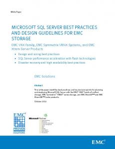


![Performance Best Practices for VMware Workstation [PDF]](https://m.moam.info/img/260x300/performance-best-practices-for-vmware-workstation-_647d723a098a9e49458b466f.jpg)

![Configuration for High Availability (HA) Best Practices [PDF]](https://m.moam.info/img/260x300/configuration-for-high-availability-ha-best-practi_64b52c11098a9ef92b8b4617.jpg)
