Emerging Yield and Reliability Challenges in Nanometer CMOS Technologies G. Gielen, P. De Wit, E. Maricau, J. Loeckx Departement Elektrotechniek ESAT-MICAS Katholieke Universiteit Leuven, Belgium
[email protected] 1
on leave from Universitat Autonoma de Barcelona, Spain
Abstract With further scaling of nanometer CMOS technologies, yield and reliability become an increasing challenge. This paper reviews the most important phenomena affecting yield and reliability. For each effect, the basic physical mechanisms causing the effect and its impact on transistor parameters are described. Possible solutions to cope/handle with these effects on the design level are discussed as well.
1. Introduction According to the ITRS Roadmap [1], reliability will be one of the most important challenges for the semiconductor industry during the following years. Smaller devices combined with new materials are the cause of the increasing yield and reliability problems. Yield can be described as the proportion of fabricated circuits which meet the design specifications once the production process has been completed. Reliability is defined as the ability of a circuit to conform to its specifications over a specified period of time under specified conditions. This paper does not give an exhaustive list of all known yield and reliability problems, but indicates some important and emerging effects in modern nanometer CMOS. This paper is organized as follows. Section 2 and 3 respectively discuss yield and time-dependent reliability problems. In section 4, environmental-dependent reliability is handled. Afterwards, some solutions to the mentioned yield and reliability issues are reviewed in section 5.
2. Variability as a yield influencing effect Non-idealities in analog and digital circuits originate from random and systematic errors in the implementation of
978-3-9810801-3-1/DATE08 © 2008 EDAA
J. Mart´ın-Mart´ınez1 , B. Kaczer, G. Groeseneken2 IMEC Leuven, Belgium R. Rodr´ıguez, M. Nafr´ıa, Universitat Autonoma de Barcelona, Spain 2
also with KU Leuven, ESAT-MICAS Department, Belgium
a circuit. These errors represent the time-independent reliability problems in a circuit. Random errors, usually denoted as variability, are the result of the stochastic nature of many physical processes that take place during the fabrication of integrated circuits. Systematic errors occur because a physical circuit implementation only approximates the ideal circuit behaviour. Both random and systematic errors have an impact on the circuit behaviour. In analog circuits device mismatch between identically designed devices limits the accuracy of the circuit while non-linearities generate distortion of the output signal. Digital circuits mostly suffer from a variable delay, reducing the overall operation speed. Mismatch is typically characterized by the random variation of the threshold voltage VT , the body factor γ and the current factor β [23], [31]. A normal distribution with mean equal to zero and variance dependent on the width W , the length L and the mutual distance D of the transistors is a widely accepted model for these random variations [5], [31]: σ 2 (∆VT ) =
A2∆VT 2 D2 + S∆V T WL
(1)
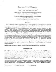
where A∆VT and S∆VT are process-dependent constants. In nanometer technologies, extra modeling terms are used to accurately model the threshold voltage variation of narrow-channel transistors and short-channel transistors [5], [41]. In this context, Tuinhout introduced a benchmark of 1mV · µm/nm of gate oxide to forecast the matching performance of scaling CMOS technologies [43]. Fig. 1 indicates the evolution of the mismatch parameter A∆VT versus the gate oxide thickness measured on large nMOS devices. But when the oxide thickness (Tox ) decreases below 10nm, this benchmark (indicated by the dashed line) is no longer holds [36], [43]. The matching is becoming only slightly better over time. Besides the above described variability issues, line edge roughness is also becoming a serious yield threatening problem [11].
Figure 1. Mismatch parameter A∆VT versus gate oxide thickness [43].
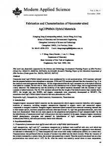
Figure 2. Illustration of the IDS -VDS characteristic of a fresh MOS transistor (solid line) compared to a degraded device (dashed line). Since mismatch is fixed after fabrication, it can be compensated to some extent, as will be illustrated in section 5.1.
3. Time-dependent reliability effects Time-dependent degradation effects will cause a change of transistor parameters (VT , β, ro ) as a function of time and therefore might turn an initially fully functional circuit into a less or even non-functional circuit over time. As explained in the following sections, this degradation depends on the stress applied to the device, i.e. the voltages and currents applied to the transistor. Fig. 2 qualitatively indicates the impact of these mechanisms on the IDS -VDS characteristic of a MOS device for an arbitrary stress time.
3.1. Time Dependent Dielectric Breakdown In ultra scaled MOSFETs, the strong electric fields across the gate oxide can cause oxide damage leading to dielectric breakdown (BD), i.e. the loss the isolating properties of the oxide. BD is an extremely local phenomenon, for which an extra current flows through a small region of the gate oxide. It becomes a crucial issue in devices and circuits reliability [1].
Prior to oxide BD, a degradation process of the dielectric takes place that initiates the generation of traps in random positions inside the oxide and at the interface. A stressinduced leakage current (SILC) is produced during this degradation stage. If the dielectric degradation increases, a critical trap density is reached and BD occurs [39]. Due to this behavior the time to BD can be described using a Weibull probability distribution. During a breakdown degradation process, different BD modes can be distinguished. Depending on the thickness of the gate oxide, one or more modes occur. The most harmful mode, the Hard-BD (HBD), provokes the complete loss of the oxide dielectric properties with gate currents in the mA range at standard operation voltages. For oxide thicknesses below 5nm, HBD can be preceeded by Soft-BD (SBD). SBD can be observed as partial loss of the dielectric properties, resulting in lower gate currents compared to HBD. Finally, in ultra-thin oxides (approximately below 2.5 nm thickness), SBD is followed by Progressive-BD (PBD), until final HDB. PBD is detected as a slow increase of the gate current over time. Concerning the BD effects in transistor characteristics, it has been shown that the degradation process prior to BD [27] and the BD spot location [14] have a strong influence on the channel current. The transistor geometry also has a strong impact on this current. Although just after SBD a very limited effect is observed [21], a significant influence on transistor characteristics is produced at longer times [21], [8]. This can be modeled as a local mobility reduction in the BD region [8]. Another important aspect of gate oxide breakdown is the fact that one BD does not necessarily implies circuit failure [20]. To analyze the BD impact on circuit performance, it is crucial to develop transistor models which take all the BD effects into account, i.e. the variation of the channel current and the increase of the gate current after BD. It should then be straightforward to implement this model in a circuit simulator [28].
3.2. Hot Carrier Injection Degradation of analog and digital circuits due to hot carrier generation has already largely been studied for more than 20 years [17], [42]. Today this phenomenon is becoming a major concern in analog and digital circuit design, due to the increasing electric fields in nanometer CMOS technologies [45], [12]. Hot Carrier Injection (HCI) manifests itself mainly as a threshold voltage shift. Degradation of carrier mobility and a change of output resistance is also observed [45], [22]. During hot carrier stress, which consists of a large electric field near the drain end of a transistor in saturation, hot carriers are produced. These carriers introduce both oxide and interface traps (near the drain) and a substrate current [17].
As holes are much ’cooler’ than electrons, hot carrier effects in nMOS devices are proven to be more significant than in pMOS devices [17]. Removal of the stress anneals some of the interface traps, resulting in partial recovery. But as these traps are only present at the drain junction of the transistor, this recovery is negligible in comparison to NBTI relaxation. HCI degradation is typically modelled with a power law dependence on the stress time t. The trapping probability of the carriers increases exponentially with increasing oxide field Eox . Besides the oxide field and the maximum lateral electric field Em , the HCI dependence on temperature T and transistor width W and length L is also reported [17], [44]. Recently Wang et al [45] proposed the following model for the threshold voltage degradation ∆VT due to hot carrier degradation: µ ¶ µ ¶ p 0 Eox φit ∆VT ∼ Qi exp exp − tn (2) Eo qλEm where Qi is the inversion charge, φit the trap generation energy and λ represents the hot electron mean free path. Eo is a process-dependent factor. Due to hot carrier degradation, electronic circuits degrade over time. In digital electronics this translates to slower circuits, but also the performance of analog circuits (e.g. gain or CMMR) is influenced. CAD tools to simulate the ageing of a circuit due to hot carriers have already been developed [24]. As scaling of technologies continues, these tools need to be improved and extended. Techniques to deal with this kind of degradation also need to be developed.
3.3. Negative Bias Temperature Instability The Negative Bias Temperature Instability (NBTI) has recently gained a lot of attention due to its increasingly adverse impact on nanometer CMOS technology [37]. NBTI is typically seen as a threshold voltage shift after a negative bias has been applied to a MOS gate at elevated temperature, mainly affecting pMOS transistors [40]. Degradation of channel carrier mobility is also observed [40], [16]. The NBTI degradation is typically represented as following a power law with stress time, although a logarithmic increase of the threshold voltage shift with stress time t has also been reported. NBTI is commonly thought to be accelerated by the electric field in the pMOS’s gate dielectric Eox , specifically the field at the substrate/dielectric interface, and by the temperature T [40]. In [40] ∆VT due to NBTI is formulated as: ∆VT ∼ exp(
−Ea Eox ) · exp( ) · tn E0 kT
(3)
where E0 and Ea are process-dependent constants. k is the
Boltzmann constant. A peculiar property of the NBTI mechanism is the socalled relaxation or recovery of the degradation immediately after the stress voltage has been reduced [10]. This greatly complicates the evaluation of NBTI, its modeling, and extrapolating its impact on circuitry. The relaxation of the threshold voltage shift has been observed to have approximately a logarithmic time dependence and spanning times from microseconds to days [29], [34]. NBTI recovery is also expected to influence the response to AC stress [15]. It currently appears that NBTI degradation does not fully recover. Separating the remaining permanent (also unrecoverable, slow, or lock-in) component from the relaxing (sometimes also referred to as recoverable or fast) component is therefore discussed by some researchers [29], [34] [15]. A single microscopic model of NBTI is not fully established yet. However, the Hydrogen release from the substrate/gate-oxide interface states [2] and the hole trapping in the gate oxide [18] are the most cited causes of NBTI.
3.4. Electromigration The problem of Electromigration (EM) is, in contrast to most other degradation effects, not located in the active devices of the circuit, but in the interconnect. EM can be described as the physical displacement of metal ions in the interconnection wires. This displacement is caused by a large flow of electrons (large current density) which interacts with the ions of the metal [6], [25]. This movement results in the formation of voids and hillocks, which respectively can cause open connections or short circuits. Since EM is accelerated near grain boundaries of the metal, vias and contact holes are more susceptible to this effect [6]. In [6] the classic formula for EM is derived in terms of the Mean Time To Failure (M T T F ): M T T F ∼ AJ −2 exp(Ea /kT )
(4)
in which J is the current density through the wire, A is the area of the cross-section of the wire and Ea is a materialdependent activation energy for EM. It can be seen that a larger cross-section area A and a smaller current density J yields a longer lifetime M T T F . As described in previous literature, better EM results can be obtained with wire widths smaller than a particular value (Bamboo effect) [25]. Wires with a limited length (Blech length) have been shown to be insensitive to EM [7]. As EM is dependent on the cross-section of a wire, the effect must be considered in the layout phase of a design. Because of the fixed thickness of the interconnect in a standard CMOS process, wires must be widened to reduce the degradation. Special layout techniques such as Slotted Wires [25] and good orientation of vias (Reservoir effect)
[30] can also be used to avoid EM problems. Some of these techniques can be applied automatically by the use of an EM-aware design flow [25].
4. Electromagnetic Compatibility as an environmental dependent reliability effect Electromagnetic Compatibility (EMC) is one of the rising challenges in current IC designs. The higher switching speeds and the recent explosion of wireless traffic generated by mobile phones, wireless networks, Bluetooth transceivers, etc... has severely affected the performance of devices in a common electromagnetic environment. In addition, the reduced supply voltage and the increased number of communication interfaces decreases the immunity to interference. EMC is defined as the ability to function satisfactorily in a common electromagnetic environment without introducing intolerable electromagnetic disturbance to anything in that environment [19]. In many applications, e.g. automotive, EMC requirements can be very tough. Making IC components intrinsically less susceptible to interference by adapted circuit design, can reduce costs substantially [33]. However, global trends in the semiconductor technology predict diverging trends between tightening IC immunity requirements and increased susceptibility of future IC’s as well as between maximum emission level and actual IC emission [38]. At present time, legislation requires IC’s to conform with international standards within the frequency range of 150kHz and 1GHz [13].
Figure 4. Electromagnetic interference can shift the DC operating point of a circuit and thereby ruin circuit functionality. current reference shown in Fig. 3. Due to circuit nonlinearity, the mean output current IOU T is pumped to a lower value. The error in output current depends on the amplitude and the frequency of the interference signal. In digital circuits, interference can introduce jitter, alter the noise margins and cause false switching events. In both cases it is important to simulate the immunity of the circuit and to indicate the problem spots in the design before tapeout, using dedicated EMC analysis tools [26].
5. Reliability and Yield resilient circuits The mechanisms described in sections 2, 3 and 4 may cause serious reliability problems in nanometer CMOS electronical systems. The classical approaches, intrinsic robustness by overdesign or use of redundancy, introduce an unacceptable power and area penalty. In order to obtain a high-performant and reliable system, using nanometer technologies, new design and analysis methods are needed to deal with the previously mentioned problems. Some of these will be discussed briefly here.
5.1. Solutions to processing variability: post-fabrication calibration Figure 3. Sample circuit in which filtering harms the EMC behaviour. Circuit nonlinearities cause the mean output current to shift.
In analog circuits, the shift of the DC operating point due to electromagnetic interference is identified as one of the major causes of failure in susceptibility tests [35], [32]. Fig. 4 illustrates the disastrous effect of interference on the
Static (time-independent) errors can be compensated by using post-fabrication calibration methods. An example of this calibration technique has been proposed and verified on silicon in [9] where it is applied on the design of a 14-bit 200MHz current-steering DAC. The high accuracy is obtained using a Switching-Sequence PostAdjustment (SSPA) calibration technique, which dynamically rearranges the switching sequence of the unary MSB current sources. Since this technique is applied after chip fabrication (calibration at runtime), random errors can partially be cancelled out. The area requirement, imposed by
of extra power dissipation and area consumption. The advantages of a system with knobs and monitors are clear [4], [3]: • A selfadaptive system is obtained. It compensates for variability and degradation induced errors, thus keeping the system in its optimal operation point of specifications and operating conditions. Figure 5. Chip photo of a variability insensitive current steering DAC [9].
• Overdesign is not needed anymore. Design specifications for a given circuit can be relaxed because multiple possible operating points exist within one system. This results in an overall decrease in power dissipation and area consumption of the entire system. Switching to another operating point might cause a slightly larger power consumption, but correct operation is guaranteed, which is a reasonable trade-off in safety-critical applications that demand absolute reliability. • The concept is applicable to both analog and digital systems.
Figure 6. General architecture of a knobs and monitor based system. the IN L property (IN L < 0.5LSB), is reduced dramatically to only 6% of the area of an intrinsic-accuracy DAC. The only extra analog building block is a current comparator. A photo of the layout is shown in Fig. 5. The total area of the chip is 3mm2 , where the area of the analog part is only 0.28mm2 . The area of the digital part (mainly the calibration controller) can be reduced by scaling in future technologies.
5.2. Solutions to time-dependent degradation: knobs and monitors concept The solution to the time-dependent problem can be found in the use of knobs and monitors as presented by Dierickx et al. [4], [3]. The idea is to continuously monitor the operation of a system or circuit and take runtime countermeasures to compensate for variability and reliability errors. This guarantees a correct and optimal operation at all times, if properly anticipated at design time by using analysis and design tools. As shown in Fig. 6, such a system consists of 3 parts. Monitors measure the actual performance of the system. Simple measurement circuits are required to achieve this. Knobs are tunable or reconfigurable circuit parts able to change the operating point of the system. Finally, a Control Algorithm selects, based on the inputs from different monitors, the optimal configuration of the system knobs in order to satisfy the system specifications, even if the performance varies over time. The control loop can be implemented in digital hardware, adding only a limited amount
5.3. Solutions to EMC related problems Solutions to the EMC problem can be found in the use of EMC analysis software [26] in order to reduce the susceptibility of a circuit to electromagnetic interference. Also, special EMC-insensitive circuits are also under investigation [33].
6. Conclusions Continuous scaling of CMOS technologies into the nanometer range has increased the effect of variability and degradation mechanisms on the yield and reliability of CMOS circuits and systems. Several effects like variability, NBTI, hot carriers, etc., have different influences on the design parameters of transistors some even time dependent. The circuits fabricated in these technologies will have to be reliability and yield resilient. This requires proper analysis tools at design time. In addition, novel design techniques such as post-fabrication calibration and the knobs and monitors concept, are needed to build reliable systems in nanometer CMOS technologies.
7. Acknowledgements This work is supported in part by FWO-Vlaanderen and IWT.
References [1] Critical Reliability Challenges for the ITRS. Technical Report Techn. Transfer #03024377A-TR, Int. Sematech, 2003.
[2] M. Alam. A critical examination of the mechanics of dynamic NBTI for PMOSFETs. Electr. Dev. Meeting, 2003. [3] Antonis Papanikolaou. Reliability issues in deep deep submicron technologies: time-dependent variability and its impact on embedded system design, 2007. [4] Bart Dierickx. Scaling below 90nm: Designing with unreliable components, 2007. [5] J. Bastos and M. Steyaert et al. Mismatch characterization of small size MOS transistors. Microel. Test Struct., 1995. [6] J. Black. Electromigration: A brief survey and some recent results. IEEE Trans on Electr. Dev., 1969. [7] I. Blech. Electromigration in thin aluminum films on titanium nitride. Journal of Applied Physics, 1976. [8] A. Cester et al. Collapse of MOSFET drain current after soft breakdown. IEEE Trans on Dev. and Mat. Rel., 2004. [9] T. Chen and G. Gielen. A 14-bit 200-MHz Current-Steering DAC With Switching-Sequence Post-Adjustment Calibration. Solid-State Circuits, IEEE Journal of, 2007. [10] G. Chen et al. Dynamic NBTI of PMOS transistors and its impact on device lifetime. Rel. Physics Symp. Proc., 2003. [11] J. Croon et al. Line edge roughness: characterization, modeling and impact on device behavior. Electr. Dev. Meeting, 2002. [12] B. Dubois et al. Analytical Modeling of Hot-Carrier Induced Degradation of MOS Transistor for Analog Design for Reliability. Proc. of the 8th Int. Symp. on Quality Electronic Design, 2007. [13] European Parliament. Directive 2004/108/EC of the european parliament and of the council of 15 december 2004 on the approximation of the laws of the member states relating to electromagnetic compatibility and repealing directive 89/336/EEC (EMC Directive). Official Journal of the European Union, 2004. [14] R. Fern´andez et al. MOSFET output characteristics after oxide breakdown. Microelectr. Eng., 2007. [15] T. Grasser et al. Simultaneous Extraction of Recoverable and Permanent Components Contributing to BiasTemperature Instability. [16] T. Grasser et al. A Rigorous Study of Measurement Techniques for Negative Bias Temperature Instability. 2007. [17] C. Hu et al. Hot-Electron-Induced MOSFET DegradationModel, Monitor, and Improvement. IEEE Trans. on Electr. Dev., 1985. [18] V. Huard et al. NBTI degradation: From physical mechanisms to modelling. Microelectr. Rel., 2006. [19] IEC 62132-1 Ed. 1.0. Integrated circuits - Measurement of electromagnetic immunity, 150 kHz to 1GHz - Part 1: General conditions and definitions. [20] B. Kaczer et al. Analysis and modeling of a digital CMOS circuit operation and reliability after gate oxide breakdown: a case study. Microelectr. Rel., 2002. [21] B. Kaczer et al. Impact of gate-oxide breakdown of varying hardness on narrow and wide nFET’s. Rel. Physics Symposium Proc., 2004. [22] I. Kurachi et al. Physical model of drain conductance, gd, degradation of NMOSFET’s due to interface state generation by hot carrierinjection. IEEE Tr. on Electr. Dev., 1994. [23] K. Lakshmikumar et al. Characterisation and modeling of mismatch in MOS transistors for precision analog design. Solid-State Circuits, IEEE Journal of, 1986.
[24] Y. Leblebici and S. Kang. Modeling and simulation of hotcarrier-induced device degradationin MOS circuits. SolidState Circuits, IEEE Journal of, 1993. [25] J. Lienig. introduction to electromigration-aware physical design. Proc. int. symposium on Physical design, 2006. [26] J. Loeckx and G. Gielen. Efficient identification of major contributions to emi-induced rectification effects in analog automotive circuits. In 17th International Zurich Symposium on Electromagnetic Compatibility, 2006. [27] J. Mart´ın-Mart´ınez et al. Lifetime estimation of analog circuits from the electrical characteristics of stressed MOSFETs. Microelectr. Rel., 2007. [28] J. Mart´ın-Mart´ınez et al. Worn-out oxide MOSFET characteristics: Role of gate current and device parameters on a current mirror. Microelectr. Rel., 2007. [29] S. Mielke and E. Yeh. Universal recovery behavior of negative bias temperature instability. Proc. IEDM, 2003. [30] H. Nguyen et al. Simulation and experimental characterization of reservoir and via layout effects on electromigration lifetime. Microelectr. Rel., 2002. [31] M. Pelgrom et al. Matching properties of MOS transistors. Solid-State Circuits, IEEE Journal of, 1989. [32] A. S. Poulton. Effect of conducted EMI on the DC performance of operational amplifiers. Electronics Letters, 1994. [33] J.-M. Redout´e and M. Steyaert. An improved current mirror structure insensitive to conducted EMI. In EMC Europe Workshop, Roma, 2005. [34] H. Reisinger et al. Analysis of NBTI Degradation-and Recovery-Behavior Based on Ultra Fast VT-Measurements. Reliability Physics Symposium Proc., 2006. [35] R. E. Richardson. Quiescent operating point shift in bipolar transistors with AC excitation. IEEE Journal of Solid-State Circuits, 1979. [36] K. Rochereau et al. Impact of pocket implant on MOSFET mismatch for advanced CMOS technology. Microel. Test Struct., 2004. [37] D. Schroder et al. Negative bias temperature instability: Road to cross in deep submicron silicon semiconductor manufacturing. Journal of Applied Physics, 2003. [38] E. Sicard et al. Towards an EMC Roadmap for Integrated Circuit. In EMC Compo 2007, 2007. [39] J. Stathis. Physical and predictive models of ultrathin oxide reliability in CMOS devices and circuits. Dev. and Mat. Rel., IEEE Trans. on, 2001. [40] J. Stathis and S. Zafar. The negative bias temperature instability in MOS devices: A review. Microelectr. Rel., 2006. [41] M. Steyaert and J. Bastos et al. Threshold voltage mismatch in short-channel MOS transistors. El. Lett., 1994. [42] S. Tam et al. Lucky-electron model of channel hot-electron injection in MOSFET’S. IEEE Tr. on Electr. Dev., 1984. [43] H. Tuinhout. Impact of parametric mismatch and fluctuations on performance and yield of deep-submicron CMOS technologies. ESSDERC, 2002. [44] W. Wang et al. Dependence of HCI mechanism on temperature for 0.18 µmtechnology and beyond. Integrated Reliability Workshop Final Report, 1999. [45] W. Wang et al. Compact Modeling and Simulation of Circuit Reliability for 65nm CMOS Technology. Measurement, 2007.