EnCache: A Dynamic Profiling Based Reconfiguration Technique for Improving Cache Energy Efficiency
SPARSH MITTAL Future Technologies Group, Oak Ridge National Laboratory (ORNL) Oak Ridge, Tennessee, 37830 United States.
[email protected] ZHAO ZHANG Department of Electrical and Computer Engineering, Iowa State University Ames, Iowa, 50014 United States.
[email protected]
With each CMOS technology generation, leakage energy consumption has been dramatically increasing and hence, managing leakage power consumption of large last-level caches (LLCs) has become a critical issue in modern processor design. In this paper, we present EnCache, a novel software-based technique which uses dynamic profiling-based cache reconfiguration for saving cache leakage energy. EnCache uses a simple hardware component called profiling cache, which dynamically predicts energy efficiency of an application for 32 possible cache configurations. Using these estimates, system software reconfigures the cache to the most energy efficient configuration. EnCache uses dynamic cache reconfiguration and hence, it does not require offline profiling or tuning the parameter for each application. Furthermore, EnCache optimizes directly for the overall memory subsystem (LLC and main memory) energy efficiency instead of the LLC energy efficiency alone. The experiments performed with an x86-64 simulator and workloads from SPEC2006 suite confirm that EnCache provides larger energy saving than a conventional energy saving scheme. For single core and dual-core system configurations, the average savings in memory subsystem energy over a shared baseline configuration are 30.0% and 27.3%, respectivelya . Keywords: Cache Energy Saving; Dynamic Profiling; Dynamic Cache Reconfiguration; Low-power; Green Computing
1. Introduction In recent years, energy efficiency has become the primary constraint in scaling the performance of processors 1 . Building an exascale machine (i.e. a machine with 1018 operations per second) within a power budget of 20 mega watts requires that each floating point operation should consume no more than 20 pico Joulesb energy 2 . However, state-of-the-art CPUs consume at least 1700 pico Joules for each floating point operation 2 . Thus, even with this optimistic estimate, performing 1018 operations per second would require at least 1700 mega watts of power. Clearly, an exascale machine built using the technology used in state-of-the-art supercomputers will consume several giga watts of power 3 . Hence, novel techniques are required a Electronic
version of an article published in Journal of Circuits, Systems and Computers, Volume 23, Issue 10, Year 2014, article DOI 10.1142/S0218126614501473, URL http://www.worldscientific.com/doi/abs/10.1142/S0218126614501473, copyright World Scientific Publishing Company. b Note: 1 pico Joule = 10−12 Joule 1
2
Sparsh Mittal and Zhao Zhang
to improve the energy efficiency of modern processors to continue to scale their performance and meet the demands of power budget. Out of different processor components, last level cachesc (LLCs) contribute significantly to the processor power consumption. In both Niagara and Niagara-2 processors, L2 cache contributes nearly 24% of the total power consumption 4 . Similarly, leakage power of last level cache (LLC) accounts for 20% and 30% of the total power in Intel Core 2 Penryn and Intel Xeon Tulsa processors 5 . Further, their size is increasing to bridge the gap between the speed of processor and main memory. As an example, Intel’s Enterprise Xeon processor uses 30 MB LLC 6 . Also, with each CMOS technology generation, leakage power has been dramatically increasing 7 . Hence, large LLCs spend a significant fraction of their energy in the form of leakage energy. Our experiments using 32nm technology node have shown that for single-core and dual-core configurations, the leakage energy of L2 cache is more than 95% of the total L2 cache energyd (dynamic energy+ leakage energy). This observation is also confirmed by the previous work 8,9,10 . Further, since for every watt of power dissipated in the computing equipment, an additional 0.5 to 1 watt of power is consumed by the cooling system 11 , the increased levels of power consumption are likely to necessitate expensive cooling solutions (e.g. liquid cooling) which would significantly increase the chip-design complexity. For these reasons, managing the power consumption of LLCs has become an important research issue in modern processor design. Given the widely different cache requirements of different programs, processor designers tend to design the LLC to fit the working sets of most applications. This, however, leads to significant wastage of cache energy for applications having working set significantly smaller than the size of LLC. To address this, several hardwarebased techniques have been proposed to save leakage energy by reducing the effective cache size (e.g. 12,13,14 ). Cache reconfiguration generally increases the number of cache misses and hence, in the worst case, downsizing the cache may dramatically increase program execution time and energy consumption in other components of the system (e.g. processor core and main memory), which may nullify the energy savings obtained in the cache. Hence, cache reconfiguration requires achieving a fine balance between energy saving and performance loss. Pure hardware-based techniques cannot take other hardware components (such as main memory) into account. Some hardware-based techniques use offline profiling 15,16,17 ; however, due to the differences between the profiled runs and the actual program execution, the effectiveness of these techniques is limited by that of profiling. Moreover, in multicore processors the number of combinations of workloads becomes very large which further limits the usefulness of offline profiling. In this paper, we present EnCache (Energy saving approach for Caches), a novel c The
cache which is accessed just before accessing the main memory is referred to as the “last level cache” which, in this paper, is the L2 cache. d The details of experimental setup are provided in Section 5.
EnCache: A Technique for Improving Cache Energy Efficiency
3
software-oriented approach with lightweight hardware support. EnCache performs cache allocation using hybrid (selective-sets and selective-ways) approach, refer Section 2 for details. For online profiling, EnCache uses a simple micro-architectural component called profiling cache. Profiling cache is a tag-only, data-less cache, which works in parallel to L2 cache. The profiling cache uses the principle of set sampling 18 to continuously profile the cache miss rates of multiple cache configurations for the running workload. Profiling cache has an energy overhead of less than 0.5% of L2 cache energy consumption. Periodically, EnCache uses an algorithm to estimate the energy efficiency of each possible cache configuration, based on the information from the profiling cache and other performance counters. Afterwards, the configuration with best energy efficiency is selected and used in the next interval. The energy saving provided by EnCache can help in reducing the requirement of cooling and it can also enable the designers to further improve performance by running extra computations within the same power budget. EnCache has several features which make it an effective technique for saving energy in product systems. EnCache does not incur time or space overhead of offline profiling (unlike 19,16,20,21 ) or compiler analysis (unlike 22 ). Also, it does not require per-block counters for tracking cache accesses to each block (unlike 23,24,13,25 ). Some previous cache energy saving techniques (e.g. 20,26,27,8 ) have been evaluated without considering their impact on components of the processor, other than cache. In contrast, we evaluate EnCache by considering both cache and main memory energy for providing a more comprehensive evaluation. This paper makes extension to our previous work 28 in eight significant ways. First, we have now evaluated EnCache using a state-of-the-art x86-64 simulator, namely Sniper which has been validated against Intel Xeon X7460 Dunnington machine 29 . Second, we have now used benchmarks from SPEC2006 suite, in place of SPEC2000 benchmarks in previous paper. Third, in addition to single-core system, we have now evaluated EnCache for dual-core system and workloads also. In total, we show results on 29 single-core and 15 dual-core workloads. Fourth, we have compared EnCache to another energy saving technique named way-adaptable cache (WAC) and have found that EnCache provides larger saving than WAC (see Section 6). Fifth, we perform energy calculations for 32nm CMOS process technology, instead of 45nm which was used in previous paper. Also, we have significantly expanded the section on related work (see Section 2) and provided qualitative comparison of EnCache with several related works. Further, to gain deeper insights, we show the results on several additional metrics (see Section 5.3). Finally, we also evaluate EnCache for additional parameters (e.g. different sampling ratio) to study its sensitivity to different parameters (see Section 6.2 and 6.3). The rest of the paper is organized as follows. Section 2 discusses the related work on cache energy saving techniques. Section 3 presents the overall architecture of EnCache. Section 4 discusses the energy saving algorithm. Section 5 presents the experimental platform, workloads, energy model and evaluation metrics. Section 6 presents the experimental results. Finally, Section 7 discusses the conclusion and
4
Sparsh Mittal and Zhao Zhang
future work. 2. Background and Related Work In recent years, managing power consumption of processors has become extremely crucial for scaling their performance 30 . To address this, researchers have used several methods of saving energy in processors, e.g. cache reconfiguration, DVFS (dynamic voltage and/or frequency scaling) etc. The limitations of DVFS techniques are that due to the recent trends of increasing leakage energy consumption with CMOS scaling, the dynamic range of power consumption that DVFS can utilize has reduced. Further, the complexity of multicore processors also reduces the effectiveness of DVFS technique 31 . EnCache uses cache reconfiguration approach for saving energy in caches. The energy consumption of caches is divided into two categories, namely leakage energy and dynamic energy. As mentioned earlier, in absence of a leakage energy saving technique, a large fraction of the energy consumption of LLCs is in the form of leakage energy. Hence, the techniques for saving dynamic energy of cache (e.g. 32,33 ) have limited utility in saving energy in LLCs. EnCache aims to save leakage energy and hence, it is very useful for modern processors which employ large-sized last level caches. The circuit-level leakage control mechanisms can be divided in two categories namely state-preserving mechanisms and state-destroying mechanisms. The statepreserving mechanisms such as drowsy circuit 23 and MTCMOS (multithreshold CMOS) circuit 13 transition the memory cell in a low-leakage mode where the data are preserved (retained). On the other hand, state-destroying mechanisms such as gated Vdd circuit 34 transition the memory cell in a low-leakage mode where the data are destroyed. The state-preserving mechanisms typically increase the noisesusceptibility of the cache 35,36 and save less energy in the low-leakage mode than the state-destroying mechanisms. For this reason, EnCache uses state-destroying leakage control mechanism (For more details, see Section 3.2). Before turning-offe the cache blocks, the dirty blocks are written back to main memory and the clean blocks are simply evicted since these blocks can be later restored from the main memory. A few techniques (e.g. 25,12 ) turn off only the data array of inactive cache regions and always keep the tag fields on. By comparison, EnCache turns off both tag and data arrays of the inactive regions to save extra amount of energy. Based on the granularity of cache reconfiguration used, existing cache management techniques can be classified as selective-ways 21,37,38,39,17,27 , selective-sets 19 , hybrid (selective-sets and selective-ways) 15 , cache-block level 24,25,23,8,13 , cache sub-block level 40,8 and cache-color level 41,42,43 . Also, some techniques use wayconcatenation 17 and configurable cache block-size 44 to achieve cache reconfiguration. Selective-ways approach does not require change in set-decoding on cache e We
use the term “turning-off” a block and using state-destroying leakage control synonymously.
EnCache: A Technique for Improving Cache Energy Efficiency
5
reconfiguration, although it provides limited granularity. Cache coloring approach requires a mapping table for translating physical address to cache color, which also increases the cache access latency. Cache block-level techniques provide fine granularity but they cannot leverage profiling, since doing that at block granularity would incur prohibitive overhead. For further discussion and comparison of these techniques, we refer the reader to previous works 45,46 . EnCache uses hybrid (selective-sets and selective-ways) approach for cache reconfiguration. By virtue of this, EnCache provides fine granularity of cache reconfiguration using caches of low-associativity (e.g. 32 possible configurations in this paper with an 8-way cache). For providing the same granularity of cache reconfiguration as EnCache, selective-ways based allocation schemes would require caches of high associativity which have high access time and access energy. Also, unlike cachecolor based allocation schemes, EnCache does not incur page migration overhead on reconfiguration and also does not require a mapping table. Some previous cache energy saving techniques (e.g. 23,27,8,24,19 ) do not directly optimize for energy; rather these techniques control other parameters (such as number of misses, access time, data duplication in the cache hierarchy etc.) with a view to save cache energy. In comparison, EnCache directly optimizes for energy (see Section 4.2). Due to this feature, EnCache can comprehensively account for different parameters (e.g. both leakage and dynamic energy) and different components (i.e. not only cache but main memory, peripherals etc.) while optimizing for energy. The decay cache technique 24 works by transitioning a block to state-destroying mode if it has not been accessed for a certain number of cycles, called decay interval. This technique is based on the generational behavior of cache block usage, which refers to the observation that cache blocks typically see a flurry of frequent use when first brought into the cache, and then see a period of “dead time” before they are evicted. By comparison, EnCache works on the principle that the unique cache blocks accessed by an application in a given time period (called the working set size) vary with time and hence, by controlling the address mapping, a suitable amount of cache can be allocated to a program and the remaining cache can be turned-off for saving leakage energy. The dynamic cache resizing technique 15 using hybrid (selective-ways and selective-sets) cache reconfiguration works by choosing a miss-bound using offline profiling which is used during actual run to guide cache reconfiguration. In comparison, our technique uses dynamic profiling to collect miss-rate estimates for different possible cache configurations. Some researchers propose cache tuning strategies for saving energy in embedded systems 44 . These works focus on proposing efficient heuristics for exploring and pruning the configuration-space for a two level cache hierarchy. Our work is different in that we focus on proposing a cache reconfiguration mechanism (viz. hybrid selective-sets and selective-ways) which uses dynamic profiling. Mittal et al. 43 propose a cache energy saving technique which uses cache coloring scheme to reconfigure the cache. For a multicore processor, this technique period-
6
Sparsh Mittal and Zhao Zhang
ically decides the cache quota of each application and the cache to be turned-off such that energy can be saved with little performance loss. A limitation of this technique is that it works only when the applications have fully disjoint address space, however it is well-known that even different applications working on separate address spaces share library code, OS (operating system) code and data. Also, with this technique, the number of configurations examined increase exponentially with number of cores which restricts the scalability of the technique. In comparison, EnCache works well for both shared and disjoint address spaces and it examines a fixed number of configurations, regardless of the number of cores. Mittal, Zhang and Cao 41 propose a technique for saving cache energy for applications with deadlines. Their technique uses number of instructions to decide the length of an interval. However, in multicore system, different cores progress at different rate due to differences in their IPC values and hence, their approach does not work well. In comparison, EnCache uses number of cycles to decide the length of an interval and hence, it can be easily implemented using a timer-based kernel module, in either single or multicore system. Also, the technique proposed in 41 is designed for QoS systems where applications have deadlines and hence, due to requirement of meeting deadlines, it may miss the opportunity of saving cache energy. In comparison, EnCache is designed for applications without deadlines, and thus, while providing performance close to baseline, EnCache does not aim at meeting deadlines. And hence, it can fully exploit the opportunity of saving cache energy. Recently, researchers have explored use of non-volatile memory (NVM) such as STT-RAM (spin-transfer torque RAM), ReRAM (resistive RAM) and PCRAM (phase change RAM) for designing LLCs 47,48 . Compared to SRAM (Static randomaccess memory), NVMs consume very small leakage power and also provide high density. However, NVMs also have some crucial limitations. Firstly, the write endurancef of NVMs is orders of magnitude smaller than that of SRAM. For example, while the write endurance of SRAM is nearly 1016 , the write endurance value of ReRAM and PCRAM are only 1011 and 108 49 . Also, for STT-RAM, although a write endurance value of 1015 has been estimated, the best endurance test result so far is less than 4 × 10¹² writes 50 . Due to this, along with the write-variation introduced by existing cache management techniques, the caches designed with NVM can fail in merely few days 49 . Further, the write latency and write energy of NVMs is much higher than that of SRAM 51 . Finally, while SRAM technology is fully mature, the above mentioned NVM technologies are much less mature. For these reasons, we have focused on widely-used SRAM cache design.
f The
write endurance of a storage device refers to the number of writes that can be applied to a device-block before it becomes unreliable.
EnCache: A Technique for Improving Cache Energy Efficiency
7
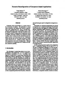
3. EnCache System Architecture In the following discussions, we assume that the LLC is an L2 cache, although the discussion can be easily applied to the case when LLC is an L3 cache. We refer to baseline cache as the cache which does not use any energy saving technique. The number of cores is denoted as N . 3.1. Profiling Cache Design Dynamic cache reconfiguration requires estimating the energy consumption of a program under different possible configurations. The energy consumption with any configuration, in turn, depends on the dynamic activity and execution time of the program with that configuration. For estimating cache miss rates under different configurations, EnCache uses profiling cache which is based on the idea of setsampling, which states that the miss rate of a cache can be estimated by sampling only a small subset of cache sets 52 . The profiling cache is a small, tag-only (data-less) cache that duplicates a small subset of the tags of the L2, with the same set associativity and replacement policy. It is decoupled from the L2 and only accepts part of L2 accesses that pass a sampling filter. The profiling cache consists of four regions (also termed as ‘levels’), which emulate a cache of 1.0, 0.5, 0.25 and 0.125 times the size of the L2, respectively. These regions are named as “F ull”, “Half ”, “Quarter” and “Eighth”. In other words, each region represents an emulated L2 of the corresponding cache size (called L2 cache state). The number of sets in each region is the number of sets in corresponding L2 cache size divided by the sampling ratio. Finite State Control
L2 Access Block Address
Address Mappers
Core Storage
M1
M2 SF Queue
Full MUX
n
Sampling Filter
FSM
Half
M3 M4
Mapped Addresses (four addresses per L2 access)
Quarter Eighth
Fig. 1: The Design of Profiling Cache
Figure 1 shows the details of the profiling cache design. The frontend logic component is shown in the left part of the figure. For each L2 access, its memory block address is sent to the sampling filter. The choice of sampling ratio RS is done
8
Sparsh Mittal and Zhao Zhang
to achieve a balance between the accuracy of profiling information collected and the overhead of the profiling cache. In this paper, we take a sampling ratio value of 64, since it enables us to reduce the overhead of profiling cache less than 0.5% of the L2 cache. As we show in Section 6.3, a higher value of RS (e.g. 128) reduces the profiling accuracy and hence, the energy saving is also reduced, while a smaller ratio (e.g. 32) improves the energy saving but also increases the profiling overhead. The sampling filter can be implemented as a simple bit shifting and matching design. An address passing the filter is passed through a small buffer queue. This helps in handling bursty accesses. Because of the relatively large sampling ratio and the fact that L2 cache is accessed much less frequently than the L1 cache, the buffer rarely overflows and if such a situation occurs, the incoming address can be discarded at the cost of potentially reduced accuracy of prediction. A memory address passing through the buffer is mapped to four cache-set indices, each of which falls into one of the four profiling-cache regions. The profiling cache is single-ported, thus the four mapped addresses are sent sequentially to the core of profiling cache, with the sequence controlled by a small finite state machine (FSM). The logic is so designed that the profiling cache can use a memory structure of one access port as its core storage. In the implementation, each address mapper splits the memory address into cache tag and cache index, and then adds a fixed offset to the cache index so that the memory address is mapped to the corresponding region. Since profiling cache does not store any data, a profiling cache “miss” does not generate any further request for other caches (since no data needs to be fetched or evicted). Rather, the LRU (least recently used) tag is evicted and the tag of the address missed is stored in its place. The profiling cache has a hit counter for each way of every cache region. The hit counter increments by one for a hit in the given way. We assume that the L2 uses the LRU replacement policy, under which a hit in a Q-way cache is also a hit in a P -way cache of the same number of cache sets if P > Q 53 , or another replacement policy of the same property. Using this property and the hit counters, EnCache algorithm predicts the cache miss rate of each way of the cache. While previous studies (e.g. 52,38 ) profile different numbers of active ways of only ‘a single level’ (namely 1.0 times the LLC size), EnCache profiles different numbers of active ways of ‘multiple levels’ (namely 1.0, 0.5, 0.25 and 0.125 times the LLC size). This difference enables EnCache to estimate energy efficiency of a large number of configurations. As experimental results show, use of only four levels suffices for the purpose of saving cache energy. For an 8-way cache, this leads to 32 possible configurations, each of which is a combination of the number of active cache sets and the number of active cache ways. To represent those configurations, we use an ordered 2-tuple (S, W ), where S and W denote the level corresponding to the number of active sets and the number of active ways, respectively. Using this notation, the baseline L2 configuration is denoted as (F ull, Assoc), which shows that in baseline cache, all sets and ways are turned on. Here F ull denotes 1.0 times
EnCache: A Technique for Improving Cache Energy Efficiency
9
the LLC size and Assoc shows the associativity of the cache. We now compute the size of profiling cache. Let QL2 and Qprof denote the number of sets in L2 and profiling cache, respectively. Let KL2 and Kprof denote the size of L2 and profiling cache, respectively. Let Fprof denote the size of profiling cache as a percentage of L2 cache size. RS denotes the sampling ratio, which is taken as 64 in this paper. Let G denote the tag size and B denote the data size, which are taken as 40 bits and 64 bytes, respectively in this paper. Assoc shows the L2 associativity. Then, we have QL2 QL2 QL2 QL2 15QL2 + + + = RS 2 × RS 4 × RS 8 × RS 8RS = Qprof × G × Assoc
Qprof =
(1)
Kprof
(2)
KL2 = QL2 × (G + B) × Assoc Kprof Fprof = × 100 KL2 15 × G = × 100 8 × (G + B) × RS
(3) (4) (5)
On substituting values, we get Fprof = 0.2%. To cross-check, we have computed areas of profiling cache and L2 cache using CACTI 54 for the cache sizes chosen in our experiments (see Section 4.1). Using these values, we find Fprof ≈ 0.1%, which is in the same range. Thus, the overhead of the profiling cache is extremely small. Further, it has data-less operation and only sampled addresses are fed to the profiling cache after the LLC access. For these reasons, it does not affect the critical path to the main LLC. The profiling cache does not share the address bus with the LLC, as its address bus can be driven by a separate address latch. Henceforth, for the sake of brevity, we simply use the term profiling cache to denote a multi-level profiling cache, unless otherwise mentioned.
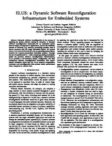
3.2. L2 Cache Controller Design Figure 2 shows the L2 cache controller design. For a W -way cache (W = 8 in our case), the controller uses a W -bit mask called way-selection mask. By controlling a particular bit Wk (for k={1, 2, ...8}), the corresponding way k can be turned on or turned off respectively. The L2 cache has an eight-bank structure. For accomplishing switching to Half , Quarter and Eighth states, cache controller keeps four, two and one bank of the cache turned-on (respectively) and turns off the rest of the banks. This is achieved by a simple logic controlled by a set-selection mask (not shown in the Figure 2). Note that the hardware mechanism to turn off a portion of LLC is already provided by the existing commercial processor chips 55 and several studies also use the approach of turning off cache banks to save leakage energy 56,57 . We define ActiveRatio as the average fraction of L2 cache lines which are turned
10
Sparsh Mittal and Zhao Zhang
L2 access address Tag+index
Hardware
Software/OS
offset Decoding
000..000 ABC
Full 000 Half 100 Quarter 110 Eighth 111
PQR
111 011 001 000
PQR
111......111 000000
Index mask 3 3
State To Mask Bits
State
Tag mask 111..111
ABC
000......000 000000
offset W1W2…..... W7W8 Used Ways Index L2 cache controller
Tag
Counters Energy Saving Algorithm
L2 cache (Tag+ data array) 8 Banks
Profile cache controller Profile cache (Tag array)
Counters
Fig. 2: L2 Cache Controller Design on over the execution of the program. Mathematically ∑I F raction(Si⋆ ) × Wi⋆ ActiveRatio = i=1 × 100 I × Assoc Si⋆ = {Full, Half, Quarter, Eighth} F raction(Si⋆ ) = {1, 0.5, 0.25, 0.125} Here I shows the total number of intervals, and (Si⋆ , Wi⋆ ) denotes the actual configuration used in an interval i. 3.3. Handling Reconfigurations The L2 cache controller uses suitable tag and index (set) masks to handle the change in set and tag decoding resulting from change in L2 state (Figure 2). The calculation for these masks for 4MB, 8-way cache with block size of 64-byte is done as follows. F ull state has 8,192 sets and hence for index mask, a total of 13 bits are required. Since Eighth state has 1024 sets, 10 least-significant-bits out of 13 bits are always set to 1. The three most-significant-bits are calculated as: a2 a1 a0 = Binary(8 × F raction(Si ) − 1). In Figure 2, these bits are shown as PQR. For a 45-bit address and 6 bits of block offset, the maximum number of bits in
EnCache: A Technique for Improving Cache Energy Efficiency
11
the tag-mask is 45 − 6 − 10 = 29, as required for Eighth state. Out of these, 26 most-significant-bits are always set to 1 since a minimum of 45 − 6 − 13 = 26 bits are required for F ull state. The three least-significant-bits are simply a2 a1 a0 . In Figure 2, these bits are shown as ABC. Since the index and tag masks are modified only at most once at the end of an interval, the address decoding can be optimized to hide the extra latency caused by the change in decoding. On change in L2 state, the existing cache data is handled as follows. When the number of cache ways (or sets) is decreased, the contents of turned-off ways (or sets) are flushed (i.e. clean blocks are discarded and the dirty blocks are written back). When the number of cache ways is increased, writeback is not required. When the number of sets is increased, the blocks in existing sets whose set index has changed are flushed. Unlike lazy repartitioning approach 42 , our approach does not require state-storage overhead for handling reconfiguration. Moreover, in some techniques such as drowsy cache method 23 , block transitions happen throughout the execution of application and hence, block transition may happen on critical path of cache access. This leads to variable latency of cache access, which makes the scheduling of dependent instructions difficult. By comparison, in EnCache the reconfigurations take place at a fixed interval boundary (e.g. 10M cycles), and hence block transitionsg do not lie at the critical path of cache access. Further, EnCache uses a large interval size and hence, the reconfiguration overhead is amortized over the length of the interval. Our experimental results have shown that the increase in L2 miss-rate and DRAM writebacks resulting from use of EnCache is quite small, which confirm that the reconfiguration overhead of EnCache is small (see Section 6). 4. Energy Saving Algorithm We first discuss our energy model and then show the working of the energy saving algorithm. 4.1. Energy Modeling We model the energy spent in L2 cache, DRAM (main memory) and the run-time cost of executing the algorithm, since other components of the processor are minimally affected by the EnCache technique. In fact, it is straightforward to extend EnCache to optimize for overall system energy efficiency by merely including processor core energy in the energy model. The energy spent in each component is the sum of its leakage energy (shown as LE) and its dynamic energy (shown as DE). Using the symbol Energy to represent the total energy consumed, we get, Energy = DEL2 + LEL2 + DEDRAM + LEDRAM + EAlgo gA
block transition refers to either turning-on or turning-off of a cache block.
(6)
12
Sparsh Mittal and Zhao Zhang
Here EAlgo denotes the energy overhead of running the algorithm. In what Leak Leak Leak follows, we use the symbols PL2 , PDRAM and Pprof to show the leakage energy per second spent in L2 cache, DRAM and profiling cache, respectively. Similarly, we Dyn Dyn Dyn use the symbols EL2 , EDRAM and Eprof to show the dynamic energy per access spent in L2 cache, DRAM and profiling cache, respectively. We show the energy calculations for an arbitrary configuration shown as ⋆ (Si , Wi⋆ ). To calculate L2 leakage energy, we note that the leakage energy depends on the L2 ActiveRatio and hence, the number of active sets and ways 19 . Thus, Leak LEL2 = PL2 × (Cyc/F req) × (W ⋆ /Assoc) × F raction(S ⋆ )
(7)
Here F raction(S ⋆ ) is defined in Section 3.2. Note that for WAC, F raction(S ⋆ ) is always equal to 1, since WAC does not change the number of sets of the cache (see Section 5.2). To calculate L2 dynamic energy, an L2 miss is assumed to consume twice the energy as that of an L2 hit 13 . The dynamic energy depends on the number of active ways 21,26,33 but is independent of the number of active sets, since it is the energy spent for accessing a read/write port. Thus, Dyn DEL2 = EL2 × (2 × ML2 + HL2 ) × (W ⋆ /Assoc)
(8)
Here, for any configuration, ML2 shows the number of L2 misses, HL2 shows the number of L2 hits, and Cyc shows the cycles consumed with that configuration. F req denotes the processor frequency. T ime and Cyc are related as T ime = Cyc/F req. The L2 energy values are obtained using CACTI 5.3 54 for 8-bank, 8-way caches with 64 byte block size at 32nm CMOS technology, and these values are shown in Table 1.
Table 1: Energy values for L2 Cache and Corresponding Profiling Cache. L2 Cache L2 Cache Size 4MB 8MB
Profiling Cache
Dyn EL2
Leak PL2
Dyn Eprof
Leak Pprof
(nJ/access) 0.7801 0.7857
(Watt) 1.2880 2.0696
(nJ/access) 0.0032 0.0045
(Watt) 0.0027 0.0045
The energy consumed by DRAM is calculated as follows. We assume that the DRAM uses aggressive power saving mode as allowed in DDR3 DRAM, and thus Leak PDRAM = 0.18nJ/nSec 58 when there is no memory access. Each DRAM access Dyn consumes 70 nJ 58 . Thus EDRAM = 70nJ. We use ADRAM to denote the total number of DRAM accesses, which includes the additional write-backs generated due to reconfigurations. Thus, Leak LEDRAM = PDRAM × Cyc/F req
(9)
EnCache: A Technique for Improving Cache Energy Efficiency Dyn × ADRAM DEDRAM = EDRAM
13
(10)
To calculate the energy-cost of the algorithm, we calculate the energy consumed by profiling cache and the energy consumed in block-transitions. EAlgo = Eprof + EX
(11)
Dyn Leak Eprof = Eprof × Cyc/F req × Aprof + Pprof
(12)
Here Aprof shows the number of profiling cache accesses and EX denotes the block transition energy (shown below). To estimate the energy-consumption of profiling-cache, we use CACTI 5.3, assuming a sampling ratio of 64. Since CACTI only provides energy values for caches having number of sets which are power-of-two, we take the closest higher powerof-two value for set-count of profiling cache for energy computation purpose. For example, the profiling cache for a 4MB, 8-way cache has 240 sets (Section 3.1). Correspondingly we calculate energy values for 256 sets. CACTI results separately present both the dynamic energy and the leakage power, along with their percentage distribution in data and tag arrays. Since the profiling cache only stores tags and no data, we take the energy values of the tag arrays only, which acts as an upper-bound of the energy consumption of the profiling cache. This is because, in the absence of data arrays, dirty bits etc., the profiling cache can be more efficiently implemented. The energy values for an 8-way associative profiling unit (assuming 8B block size) are shown in Table 1. Since for every 64 L2 accesses, profiling cache is accessed only 4 times, we conclude that the energy consumption of profiling unit is a very small fraction of the L2 energy consumption. We assume that each block-transition activity consumes 0.002 nJ. If total number of transitions are shown by N umT ran, then the total block-transition energy EX is calculated as EX = 0.002 × N umT ran nanoJoules
(13)
We mention that for baseline experiments, EAlgo = 0 and for WAC technique Eprof = 0, since the WAC technique does not use profiling-cache. For each of the 32 configurations explored, EnCache maintains hardware counters to measure L2 misses, energy values etc. Many processors already contain extra counters for measuring performance or for operating system 24 . These can be used as global counters, and hence the overhead of counters is ignored in energy calculations. 4.2. Algorithm Details It is well-known that different applications and even different phases of the same application may have different active working set size (WSS). In any interval, by allocating just minimum LLC space to an application so that its working set can fit, the rest of the L2 cache can be turned off to save leakage energy with little impact
14
Sparsh Mittal and Zhao Zhang
on performance. Based on this observation, at the end of each interval, the system software is designed to use Algorithm 1 to choose a configuration with minimum estimated energy. Initially, the cache configuration is (F ull, Assoc). Algorithm 1 EnCache: Algorithm For Energy Saving Input: M isses estimates for all configurations Output: Best State and W ays for interval i + 1 1: Let (Si⋆ , Wi⋆ ) be the configuration in the interval i. 2: Energy ⋆ = ∞, S ⋆ = -1, W ⋆ = -1 3: for S = {F ull,Half ,Quarter, Eighth} do 4: for W = 1 to Assoc do 5: Estimate Energyi (S,W ) 6: if Energyi (S,W ) < Energy ⋆ then 7: Energy ⋆ = Energyi (S,W ), S ⋆ = S, W ⋆ = W 8: end if 9: end for 10: end for (Energy(Si⋆ , Wi⋆ ) − Energy ⋆ ) × 100 11: Let ∆E = Energy(Si⋆ , Wi⋆ ) 12: if ∆E > λ then 13: RETURN (S ⋆ , W ⋆ ) for interval i + 1 14: else 15: RETURN (Si⋆ , Wi⋆ ) for interval i + 1 16: end if
The algorithm works as follows. Since future values are unavailable, the algorithm uses the observed values from an interval to make predictions for the next interval. The estimate of number of misses for different configurations is obtained from profiling cache which acts as the input to the algorithm. Using these values, the energy estimate is computed for all the configurations. The interval size is decided by the number of cycles and thus, the time duration of the interval is same, regardless of the configuration and hence, L2 leakage energy for a configuration depends on its ActiveRatio, i.e. the number of sets and ways. The L2 dynamic energy for a configuration depends on the number of misses and hits and this information is already available from the profiling cache. The profiling cache energy and DRAM leakage energy is same for all configurations. The DRAM dynamic energy for a configuration depends on the number of DRAM accesses which depend on the number of L2 misses and writebacks. Number of L2 misses are already available. To estimate writebacks, we note that a writeback is issued when a dirty cache block is evicted on a cache miss. We keep a counter, denoted as nDirty, which records the number of dirty blocks in the cache. To maintain this counter, scanning the cache is not required. Instead, each time a dirty block
EnCache: A Technique for Improving Cache Energy Efficiency
15
is inserted (resp. evicted), the counter is incremented (resp. decremented). Also, for any configuration, the number of active (i.e. not turned-off, either valid or invalid) blocks is equal to the number of sets multiplied by the number of ways in that configuration. Then, the ratio of nDirty and number of active blocks shows the fraction of dirty blocks in the cache. Multiplying this ratio with the L2 miss estimate, gives the estimate of writebacks in that configuration. Since the exact number of dirty evicted blocks depends on other factors also, such as replacement policy, there is some inaccuracy in the above estimation. However, this has only a small effect on the total energy estimate, since most applications bring only a small number of dirty blocks and a statistical estimate is expected to provide good accuracy on average. The energy of block-transitions depends on the number of blocks which would be turned-on or turned-off in reconfiguring from current configuration to a next configuration and hence, it can be easily computed. Using these energy estimates, the configuration with the minimum energy can be easily selected. The algorithm uses a parameter λ. Reconfiguration to another configuration is only done if it is expected to provide at least λ% improvement in energy over the existing configuration. In this paper, the value of λ has been heuristically set to 1%. 4.3. Algorithm Implementation The algorithm itself is implemented in the software. Because of a large interval size, energy calculations need to be done infrequently and thus, the overhead of energy computations is amortized over the entire interval. The OS uses a timerbased interrupt to enforce the intervals. At the end of each interval, a low-overhead software handler is invoked which executes the algorithm and enforces the new configuration. The algorithm does not require compiler analysis or any changes to the program binaries. 5. Experimental Methodology 5.1. Simulation Platform and Workload To evaluate EnCache, we perform out-of-order simulations using interval core model in Sniper x86-64 multi-core simulator 29 , which has been verified against real hardware. Each core has a frequency of 2.2 GHz, dispatch width of 4 micro-operations and reorder buffer of 128 entry. For both single-core and dual-core system, L1I and L1D are 32KB, 4-way, LRU caches with 2 cycle latency. For dual-core system, L1I and L1D caches are private to each core and L2 cache is shared among the cores. The L2 cache is unified 8-way, LRU and its size for single-core and dual-core simulations are 4MB and 8MB respectively. L2 latency is 12 cycles. Main memory latency is 154 cycles. Peak memory bandwidth is 12.8 GB/s and memory queue contention is also modeled. Interval length is 10M cycles. We have used all 29 SPEC CPU2006 benchmarks with ref inputs. For single-core
16
Sparsh Mittal and Zhao Zhang
system, each benchmark is used as a workload, thus providing 29 workloads. For dual-core system, we randomly combine different benchmarks, such that except for completing the left-over group, each benchmark is used exactly once, thus providing 15 workloads. These workloads are shown in Table 2 and 3.
Table 2: Workloads For Single-Core System and Their Acronyms Workload
Acronym
Workload
Acronym
Workload
Acronym
astar bwaves bzip2 cactusADM calculix dealII gamess gcc gemsFDTD gobmk
As Bw Bz Cd Ca Dl Ga Gc Gm Gk
gromacs h264ref hmmer lbm leslie3d libquantum mcf milc namd omnetpp
Gr H2 Hm Lb Ls Lq Mc Mi Nd Om
perlbench povray sjeng soplex sphinx tonto wrf xalancbmk zeusmp
Pe Po Sj So Sp To Wr Xa Ze
Table 3: Workloads For Dual-Core System and Their Acronyms Workload
Acronym
Workload
Acronym
astar-dealII gcc-leslie gemsFDTD-gromacs lbm-xalan bzip2-libquantum omnetpp-soplex namd-cactusADM calculix-tonto
AsDl GcLs GmGr LbXa BzLq OmSo NdCd CaTo
sphinx-mcf libquantum-milc sjeng-wrf bwaves-zeusmp hmmer-gamess gobmk-h264ref perlbench-povray
SpMc LqMi SjWr BwZe HmGa GkH2 PePo
Each benchmark was fast-forwarded for 10B instructions and the workloads were simulated till each core completed at least 1B instructions. For dual-core system, a core that has finished its 1B instructions continues to run (so that it contends for the shared resources, e.g. L2 cache), but its IPC is recorded only for the first 1B instructions, following previous works 52,27 . Energy values are recorded for the entire simulation, following 16 . We have used the above mentioned measurement procedure since IPC is a per-core metric, while energy is a system-wide metric. The intuition behind this is that applications execute different codes during different execution intervals, and it is only meaningful to compare cycles consumed to execute the same piece of code in baseline and EnCache (or WAC). Also, since energy is computed for the entire execution, it is not possible to artificially slow-down an application after its completion to benefit other application(s), since this would dramatically
EnCache: A Technique for Improving Cache Energy Efficiency
17
increase the miss-rate of slowed-down application which would reflect in undue increase in parameters such as memory queue contention, execution time, DRAM energy and ultimately, it would reflect in increased total energy consumption. Thus, our measurement procedure is fair and foolproof and it takes into account the effect of performance loss on energy consumption. Finally, in real-world, IPC for each core can be measured using hardware performance counters, which are available on processors from most commercial vendors (e.g. Intel and AMD etc. 59,60 ) and energy/power consumption can be measured using a watt-meter. 5.2. Comparison with Way-Adaptable Cache (WAC) Technique We compare EnCache with a conventional selective-ways technique, called wayadaptable cache (WAC) 14 . WAC works by keeping only few MRU (most recently used) ways in each set of the cache active to save energy. In WAC algorithm, reconfiguration is checked after every K cache hits. WAC computes the ratio (say Q) of hits to the least recently used active way and the MRU way of the cache. Further, it uses two threshold values, viz. T1 and T2 . When Q < T1 , it is assumed that most accesses to the cache hit near MRU ways and hence, if at least three ways are active, a single cache way is turned off. Conversely, when Q > T2 , it is assumed that the cache hits are uniformly distributed over different ways and hence, if at least one way is turned off, a single cache way is turned on 14 . We take T1 = 0.005, T2 = 0.02, K = 100, 000 following 14 . We have chosen WAC since like EnCache, WAC also uses state-destroying leakage control. Also, unlike some other energy saving techniques (e.g. 19 ), WAC does not necessitate finding per-application value of its parameters using offline profiling and hence can be more easily used in multicore systems. 5.3. Metrics We show the results on following metrics. (1) Percentage saving in Energy, as defined in Eq. 6. (2) Weighted speedup (or simply speedup), defined as i=N ∑−1 IP Ci (scheme) /N Speedup = IP Ci (baseline)
(14)
i=0
Here scheme refers to either EnCache or WAC and baseline refers to the baseline cache. (3) ActiveRatio (see Section 3.2) (4) Absolute increase in L2 MPKI (miss-per-kilo-instruction) (5) Absolute increase in DRAM WPKI (writes-per-kilo-instruction) Across the workloads, weighted speedup (and fair speedup shown below) is averaged using geometric mean and all other quantities are averaged using arithmetic
18
Sparsh Mittal and Zhao Zhang
mean since they can be negative or zero. Studying the change in L2 MPKI and DRAM WPKI helps us in getting insights into the flush overhead of EnCache and also its effect on DRAM traffic and memory queue contention. To quantify the increase in L2 MPKI and DRAM WPKI, we use absolute difference values instead of percentage values, following previous works 61 . The motivation for this is that the miss rate and DRAM writes of some benchmarks can be arbitrarily small and hence, a small change in cache miss rate may show up as a large percentage change, distorting its contribution to performance. To get insights into the cost of running algorithm, we also compute the fractional overhead of running algorithm (Θ(scheme)) which is defined as Θ(scheme) =
EAlgo (scheme) × 100 Energy(baseline)
For dual-core system, we have also computed fair speedup
(15) 42
, which is defined
as F air Speedup = N/
i=N ∑−1 i=0
IP Ci (baseline) IP Ci (scheme)
(16)
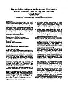
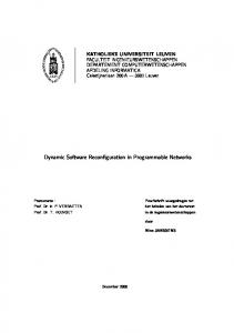
We have found the fair speedup values to be almost same as the weighted speedup values. As we show in the results section, the average value of weighted speedup is close to one (> 0.98), and similarly the average value of fair speedup is also close to one. Thus, EnCache does not cause unfairness or thread-starvation. For sake of brevity, we omit these results. 6. Results and Analysis 6.1. Main Results Figures 3 and 4 show the results on energy saving, speedup and ActiveRatio for single core and dual-core system, respectively. For the remaining metrics, we omit the per-workload figures for brevity and only state the average. The average increase in L2 MPKI and DRAM WPKI for single-core system for EnCache (WAC) are 0.47 (0.16) and 0.18 (0.06), respectively. For dual-core system, these values for EnCache (WAC) are 0.58 (0.21) and 0.19 (0.06), respectively. We now analyze the results further. Firstly, it is clear that EnCache provides larger energy savings than WAC for both single-core and dual-core systems. For single-core system, the average energy savings using EnCache and WAC are 30.0% and 23.3%, respectively. For dual-core system, these values are 27.3% and 20.8%, respectively. For some workloads such as mcf, soplex, xalan, LbXa (lbm-xalan) etc., both techniques do not reconfigure the cache. This is because these workloads use L2 cache intensely and hence, turning off cache would actually increase the energy and not save energy. For other workloads, such as povray, bwaves, PePo (perlbench-
EnCache: A Technique for Improving Cache Energy Efficiency
80 70 60 50 40 30 20 10 0 -10
% Energy saved (single-core system)
EnCache
As Bw Bz Cd Ca Dl Ga Gc Gm Gk Gr H2 Hm Lb
Ls
Lq Mc Mi Nd Om Pe Po
Sj
19
WAC
So Sp To Wr Xa Ze Avg
(a) Percentage Energy Saving 1
EnCache
Speedup (single-core system)
WAC
0.98 0.96 0.94 0.92 0.9 As Bw Bz Cd Ca Dl Ga Gc Gm Gk Gr H2 Hm Lb Ls Lq Mc Mi Nd Om Pe Po Sj So Sp To Wr Xa Ze Avg
(b) Speedup 100
EnCache
ActiveRatio (single-core system)
WAC
80 60 40 20 0 As Bw Bz Cd Ca Dl Ga Gc Gm Gk Gr H2 Hm Lb Ls Lq Mc Mi Nd Om Pe Po
Sj
So Sp To Wr Xa Ze Avg
(c) ActiveRatio
Fig. 3: Results For Single-core System povray) etc., both techniques save large amount of energy since these workloads do not use L2 cache intensely. A crucial limitation of WAC is that it decides the end of an interval by the number of cache hits. However, for applications with small number of hits, the interval size becomes very large and for streaming applications, the hit rate is zero and hence, for such applications WAC fails to perform any cache reconfiguration. In contrast, EnCache uses number of cycles to decide the interval size and thus, it applies reconfiguration for all the workloads. WAC must keep at least 2 of the cache ways always ON. For an 8-way cache, this represents 25% of the cache and for a 4-way cache, this represents 50% of the cache. Thus, for a 8-way cache, WAC cannot reduce the cache ActiveRatio below 25% and hence, it cannot reduce the energy further. EnCache, on the other hand, uses both selective-sets and selective-ways and hence, can turnoff a larger portion of cache to save extra amount of energy. This fact is reflected in the results on cache ActiveRatio and energy savings. With EnCache, the configuration with the lowest size is (Eighth, 1), which for a 8-way cache represents nearly 2% of the cache size. Thus, EnCache can turnoff nearly up to 98% of the cache, as can be seen from the ActiveRatio of libquantum (Lq). Although WAC employs a simple mechanism for deciding cache reconfiguration, it fails to account for the relative energy consumption of different components such
Sparsh Mittal and Zhao Zhang
20
80 70 60 50 40 30 20 10 0 -10
% Energy saved (2-core system)
AsDl
GcLs
GmGr
LbXa
BzLq
EnCache
OmSo
NdCd
CaTo
SpMc
LqMi
SjWr
BwZe
HmGa
WAC
GkH2
PePo
Avg
(a) Percentage Energy Saving EnCache
Speedup (2-core system)
1
WAC
0.98 0.96 0.94 0.92 0.9 AsDl
GcLs
GmGr
LbXa
BzLq
OmSo
NdCd
CaTo
SpMc
LqMi
SjWr
BwZe
HmGa
GkH2
PePo
Avg
(b) Speedup 100
EnCache
ActiveRatio (2-core system)
WAC
80 60 40 20 0 AsDl
GcLs
GmGr
LbXa
BzLq
OmSo
NdCd
CaTo
SpMc
LqMi
SjWr
BwZe
HmGa
GkH2
PePo
Avg
(c) ActiveRatio
Fig. 4: Results For Dual-core System as cache and DRAM. Choosing proper values of different parameters such as T1 , T2 and K requires either offline profiling or some insights into the nature of workloads. Moreover, these parameters do not directly relate to energy saving and hence, do not provide insights into energy consumption characteristics of the applications. In contrast, EnCache directly optimizes for energy, and hence, it intrinsically takes into account the relative energy consumption of different components and uses this to adjust its aggressiveness of cache turnoff. To avoid high reconfiguration overhead, WAC only changes one way at a time. In comparison, using dynamic profiling EnCache estimates the energy consumption of different configurations and hence, it can make large changes in cache size (if required) and thus, it adapts to the changing working set size of the application much more quickly. For some workloads, WAC saves larger amount of energy than EnCache, e.g. Ca (calculix), Lb (lbm), BwZe (bwaves-zeusmp), etc. For these workloads, EnCache overestimates the reconfiguration overhead and hence, turnsoff smaller fraction of cache than WAC. For single-core system, the average value of speedup with EnCache and WAC are 0.98 and 0.99, respectively; and for two-core system also, these values are 0.98 and 0.99, respectively. Thus, the speedup (or slow-down) of both the techniques are nearly same, with the speedup of EnCache being slightly smaller. This is due to the fact that EnCache uses more aggressive cache reconfiguration. However, given
EnCache: A Technique for Improving Cache Energy Efficiency
21
the fact that the difference is small and the overhead of performance loss has been accounted in energy model, we can conclude that on average, EnCache does not sacrifice performance for saving energy and maintains the performance close to the baseline while saving more than 25% energy. EnCache technique increases both L2 MPKI and DRAM WPKI more than the WAC technique. This is expected since EnCache turns off cache more aggressively. Still, note that the difference is small and the extra energy dissipated is more than offset by the savings achieved from cache turnoff. Also, on using EnCache, the increase in MPKI is always less than 0.7 and increase in WPKI is always less than 0.2, which confirms that the reconfiguration overhead of EnCache is small. For EnCache, the value of Θ for single-core and dual-core are 0.13% and 0.12% and for WAC, these values are almost zero. Thus, the energy overhead of EnCache algorithm is extremely small and given the large energy savings provided by EnCache, a negligibly small overhead is justified. 6.2. Results on Changing the Optimization Target and Baseline Cache Size We now evaluate EnCache and WAC for the case when the optimization target or the baseline cache size is altered. 6.2.1. Changing the Optimization Target To show the flexibility of EnCache, we exclude DRAM energy h from our energy model and thus, evaluate the techniques based on how well they optimize the L2 cache energy alone (we still account for algorithm overhead). In other words, EnCache algorithm now only estimates L2 energy and the energy saving comparisons are only made based on L2 energy and algorithm overhead. Table 4 summarizes these results. It is clear that when only L2 (and algorithm) energy is modeled, the margin between EnCache and WAC can be seen to be much larger. For N = 1 and 2, EnCache provides 63% and 54% energy savings, respectively, while WAC provides only 37% and 33% savings, respectively. Also, compared to the main results shown above, EnCache now turns off the cache more aggressively since the scope of energy saving is increased. This shows that EnCache easily adapts itself for different optimization targets. In comparison, a direct relationship does not exist between the optimization target and the parameters of WAC. 6.2.2. Changing the Baseline Cache Size To evaluate the techniques further, we reduce the L2 cache size to half of its default value. Specifically, for single-core system, we change the L2 cache size to 2MB and for dual-core system, we change the L2 cache size to 4MB. Table 5 summarizes h Note
that DRAM energy is excluded only for the experiments shown in Section 6.2.1
22
Sparsh Mittal and Zhao Zhang
Table 4: Results when only L2 and algorithm energy is modeled
EnCache WAC
% Energy Saved N =1 N =2 62.53 53.76 36.52 32.87
Speedup N =1 N =2 0.96 0.97 0.99 0.99
ActiveRatio N =1 N =2 35.19 44.67 63.10 66.89
MPKI N =1 1.01 0.16
Inc. N =2 0.74 0.20
WPKI N =1 0.37 0.06
Inc. N =2 0.24 0.06
these results. It is clear that EnCache still provides larger energy saving compared to WAC. Compared to the default case, reducing the cache size to half also reduces its contribution to the memory subsystem energy and hence, the scope of energy saving is also reduced. Table 5: Results on reducing the L2 cache size to half (i.e. 2MB L2 for single-core and 4MB L2 for dual-core system)
EnCache WAC
% Energy Saved N =1 N =2 17.57 16.95 13.77 12.54
Speedup N =1 N =2 0.97 0.97 0.99 0.99
ActiveRatio N =1 N =2 50.56 42.46 70.71 75.32
MPKI N =1 0.64 0.10
Inc. N =2 0.79 0.12
WPKI N =1 0.18 0.03
Inc. N =2 0.20 0.03
6.3. Parameter Sensitivity Study We now focus exclusively on EnCache and study its sensitivity to different parameters. In each case, we only change one parameter from the default parameters shown in Section 5.1 and summarize the results in Table 6. The energy values of profiling cache for different sampling ratio were separately calculated and are omitted for brevity. Table 6: Energy saving, Speedup, ActiveRatio, L2 MPKI Increase and DRAM WPKI Increase for different parameters. Default parameters: interval size = 10M cycle, RS = 64.
Default Interval=5M Interval=20M RS = 32 RS = 128
% Energy Saved N =1 N =2 30.0 27.3 28.6 26.6 31.1 26.7 31.2 27.4 30.4 27.2
Speedup N =1 N =2 0.98 0.98 0.98 0.97 0.98 0.98 0.98 0.98 0.98 0.98
ActiveRatio N =1 N =2 45.9 46.2 46.1 46.0 45.4 47.5 43.8 46.2 44.5 46.5
MPKI N =1 0.47 0.55 0.44 0.44 0.53
Inc. N =2 0.58 0.62 0.56 0.57 0.57
WPKI Inc. N =1 N =2 0.18 0.19 0.20 0.20 0.16 0.18 0.17 0.19 0.18 0.19
6.3.1. Change in Interval Size On changing the interval size to 5M cycles, the energy savings are slightly reduced; which can be attributed to the fact that smaller interval size leads to more aggressive
EnCache: A Technique for Improving Cache Energy Efficiency
23
cache reconfiguration and the associated overhead. This is also evident from the fact that the increase in MPKI and WPKI become larger for the interval size of 5M cycles. For the interval size of 20M cycles, the opportunity of energy saving through reconfiguration is reduced but the reconfiguration overhead is also reduced. Due to the combined effect of these two factors, the energy savings show small difference from the default case. Still, we observe that for both 5M and 20M interval size, EnCache provides more than 28% energy saving for single-core and more than 26% saving for dual-core system. Also the average speedup is greater than or equal to 0.97 for all the cases. 6.3.2. Change in Sampling Ratio For sampling ratio values of 32 and 128, EnCache still provides more than 30% average energy savings for single-core system and more than 27% saving for dualcore system. Also, the average speedup is greater than or equal to 0.98 and thus, the performance loss is small. Specifically, from large energy saving values at Rs = 128, we can conclude that by increasing the sampling ratio, the overhead of profiling cache and hence, the overhead of algorithm can be further reduced. The results presented in this section confirm that EnCache works well for a wide range of parameters. This feature makes EnCache extremely suitable for product systems. 7. Conclusion In this paper, we have proposed EnCache, a novel software-level approach for saving leakage energy of last-level caches. Using a low-cost hardware component called profiling cache, system software estimates memory-subsystem energy of a program for multiple cache configurations. To maintain a fine balance between energy saving and performance loss, EnCache uses dynamic performance regulation technique. The experiments performed over a state-of-the-art x86-64 simulator and SPEC2006 workloads show that EnCache is effective and saves larger energy than a conventional energy-saving scheme. Our future work will focus on synergistically using other methods of reducing L2 cache miss rate to further bring down the cache reconfiguration overhead. References 1. S. Borkar and A. A. Chien, “The future of microprocessors,” Communications of the ACM, vol. 54, no. 5, pp. 67–77, 2011. 2. S. W. Keckler, W. J. Dally, B. Khailany, M. Garland, and D. Glasco, “GPUs and the future of parallel computing,” Micro, IEEE, vol. 31, no. 5, pp. 7–17, 2011. 3. R. Miller, http://www.datacenterknowledge.com/archives/2010/12/ 10/exascale-computing-gigawatts-of-power/, 2010. 4. S. Li, J. Ahn, R. Strong, J. Brockman, D. Tullsen, and N. Jouppi, “McPAT: an integrated power, area, and timing modeling framework for multicore and manycore
24
5.
6. 7.
8.
9.
10. 11.
12.
13.
14.
15.
16.
17.
18. 19.
20.
Sparsh Mittal and Zhao Zhang
architectures,” in 42nd IEEE/ACM International Symposium on Microarchitecture (MICRO), 2009, pp. 469–480. S. Li, K. Chen, J. H. Ahn, J. B. Brockman, and N. P. Jouppi, “CACTI-P: Architecture-level modeling for SRAM-based structures with advanced leakage reduction techniques,” in International Conference on Computer-Aided Design (ICCAD), 2011, pp. 694–701. Intel, http://ark.intel.com/products/53580/, 2014. S. Rodriguez and B. Jacob, “Energy/power breakdown of pipelined nanometer caches (90nm/65nm/45nm/32nm),” in International Symposium on Low Power Electronics and Design (ISLPED), 2006, pp. 25–30. L. Li, I. Kadayif, Y.-F. Tsai, N. Vijaykrishnan, M. Kandemir, M. Irwin, and A. Sivasubramaniam, “Leakage energy management in cache hierarchies,” International Conference on Parallel Architectures and Compilation Techniques (PACT), pp. 131 – 140, 2002. H. Homayoun, A. Veidenbaum, and J. Gaudiot, “Adaptive techniques for leakage power management in L2 cache peripheral circuits,” International Conference on Computer Design (ICCD), pp. 563–569, 2008. A. Agarwal, H. Li, and K. Roy, “DRG-cache: a data retention gated-ground cache for low power,” in 39th Design Automation Conference (DAC), 2002, pp. 473–478. C. D. Patel, C. E. Bash, R. Sharma, M. Beitelmal, and R. Friedrich, “Smart cooling of data centers,” Pacific RIM/ASME International Electronics Packaging Technical Conference and Exhibition (IPACK03), 2003. J. Abella, A. Gonz´ alez, X. Vera, and M. O’Boyle, “IATAC: a smart predictor to turnoff L2 cache lines,” ACM Transactions on Architecture and Code Optimization, vol. 2, no. 1, pp. 55–77, 2005. H. Hanson, M. Hrishikesh, V. Agarwal, S. Keckler, and D. Burger, “Static energy reduction techniques for microprocessor caches,” IEEE Transactions on VLSI Systems, vol. 11, no. 3, pp. 303–313, 2003. A. Bardine, M. Comparetti, P. Foglia, G. Gabrielli, C. Prete, and P. Stenstr¨ om, “Leveraging data promotion for low power D-NUCA caches,” in EUROMICRO Conference on Digital System Design Architectures, Methods and Tools, 2008, pp. 307–316. S. Yang, B. Falsafi, M. Powell, and T. Vijaykumar, “Exploiting choice in resizable cache design to optimize deep-submicron processor energy-delay,” in International Symposium on High-Performance Computer Architecture (HPCA), 2002, pp. 151– 161. W. Wang, P. Mishra, and S. Ranka, “Dynamic cache reconfiguration and partitioning for energy optimization in real-time multi-core systems,” in Design Automation Conference (DAC), 2011, pp. 948–953. C. Zhang, F. Vahid, and W. Najjar, “A highly configurable cache for low energy embedded systems,” ACM Transactions on Embedded Computing Systems (TECS), vol. 4, no. 2, pp. 363–387, 2005. R. Kessler, M. Hill, and D. Wood, “A comparison of trace-sampling techniques for multi-megabyte caches,” IEEE Trans. on Computers, vol. 43, no. 6, pp. 664–675, 1994. S. Yang, B. Falsafi, M. D. Powell, K. Roy, and T. N. Vijaykumar, “An integrated circuit/architecture approach to reducing leakage in deep-submicron high-performance I-caches,” International Symposium on High-Performance Computer Architecture (HPCA), pp. 147–157, 2001. X. Jiang, A. Mishra, L. Zhao, R. Iyer, Z. Fang, S. Srinivasan, S. Makineni, P. Brett, and C. R. Das, “ACCESS: Smart scheduling for asymmetric cache CMPs,” in International Symposium on High Performance Computer Architecture (HPCA), 2011, pp.
EnCache: A Technique for Improving Cache Energy Efficiency
25
527–538. 21. D. H. Albonesi, “Selective cache ways: on-demand cache resource allocation,” in International Symposium on Microarchitecture (MICRO), 1999, pp. 248–259. 22. W. Zhang, J. Hu, V. Degalahal, M. Kandemir, N. Vijaykrishnan, and M. Irwin, “Compiler-directed instruction cache leakage optimization,” in International Symposium on Microarchitecture (MICRO), 2002, pp. 208–218. 23. K. Flautner, N. Kim, S. Martin, D. Blaauw, and T. Mudge, “Drowsy caches: simple techniques for reducing leakage power,” in International Symposium on Computer Architecture (ISCA), 2002, pp. 148–157. 24. S. Kaxiras, Z. Hu, and M. Martonosi, “Cache decay: exploiting generational behavior to reduce cache leakage power,” in International symposium on Computer architecture (ISCA), 2001, pp. 240–251. 25. H. Zhou, M. Toburen, E. Rotenberg, and T. Conte, “Adaptive mode control: A staticpower-efficient cache design,” ACM Transactions on Embedded Computing Systems, vol. 2, no. 3, pp. 347–372, 2003. 26. I. Kotera, K. Abe, R. Egawa, H. Takizawa, and H. Kobayashi, “Power-aware dynamic cache partitioning for CMPs,” Transactions on high-performance embedded architectures and compilers III, pp. 135–153, 2011. 27. K. T. Sundararajan, V. Porpodas, T. M. Jones, N. P. Topham, and B. Franke, “Cooperative partitioning: Energy-efficient cache partitioning for high-performance CMPs,” in International Symposium on High Performance Computer Architecture (HPCA), 2012, pp. 1–12. 28. S. Mittal and Z. Zhang, “EnCache: Improving cache energy efficiency using a softwarecontrolled profiling cache,” IEEE International Conference On Electro/Information Technology, May 2012. 29. T. E. Carlson, W. Heirman, and L. Eeckhout, “Sniper: Exploring the level of abstraction for scalable and accurate parallel multi-core simulations,” in International Conference for High Performance Computing, Networking, Storage and Analysis (SC), 2011, pp. 1–12. 30. S. Mittal, “A Survey of Architectural Techniques For DRAM Power Management,” International Journal of High Performance Systems Architecture, vol. 4, no. 2, pp. 110–119, 2012. 31. E. Le Sueur and G. Heiser, “Dynamic voltage and frequency scaling: The laws of diminishing returns,” in International conference on Power aware computing and systems. USENIX Association, 2010, pp. 1–8. 32. A. Udipi, N. Muralimanohar, and R. Balasubramonian, “Non-uniform power access in large caches with low-swing wires,” in International Conference on High Performance Computing (HiPC). IEEE, 2009, pp. 59–68. 33. M. Powell, A. Agrawal, T. Vijaykumar, B. Falsafi, and K. Roy, “Reducing setassociative cache energy via way-prediction and selective direct-mapping,” in International Symposium on Microarchitecture (MICRO), 2001, pp. 54–65. 34. M. Powell, S.-H. Yang, B. Falsafi, K. Roy, and T. Vijaykumar, “Gated-Vdd: a circuit technique to reduce leakage in deep-submicron cache memories,” in International Symposium on Low Power Electronics and Design (ISLPED), 2000, pp. 90 – 95. 35. J. Ayala, M. Lopez-Vallejo, D. Atienza, P. Raghavan, F. Catthoor, and D. Verkest, “Energy-aware compilation and hardware design for VLIW embedded systems,” International Journal of Embedded Systems, vol. 3, no. 1, pp. 73–82, 2007. 36. L. Li, V. Degalahal, N. Vijaykrishnan, M. Kandemir, and M. J. Irwin, “Soft error and energy consumption interactions: a data cache perspective,” in International Symposium on Low Power Electronics and Design (ISLPED), 2004, pp. 132–137.
26
Sparsh Mittal and Zhao Zhang
37. S. Mittal, Z. Zhang, and J. S. Vetter, “FlexiWay: A cache energy saving technique using fine-grained cache reconfiguration,” in IEEE 31st International Conference on Computer Design (ICCD), 2013, pp. 100–107. 38. K. Kedzierski, F. J. Cazorla, R. Gioiosa, A. Buyuktosunoglu, and M. Valero, “Power and performance aware reconfigurable cache for CMPs,” in International Forum on Next-Generation Multicore/Manycore Technologies. ACM, 2010. 39. S. Mittal, J. S. Vetter, and D. Li, “Improving energy efficiency of Embedded DRAM Caches for High-end Computing Systems,” in International ACM Symposium on High Performance Parallel and Distributing Computing (HPDC), 2014, pp. 99–110. 40. M. A. Alves, E. Ebrahimi, V. T. Narasiman, C. Villavieja, P. O. Navaux, Y. N. Patt et al., “Energy savings via dead sub-block prediction,” in 24th International Symposium on Computer Architecture and High Performance Computing (SBAC-PAD). IEEE, 2012, pp. 51–58. 41. S. Mittal, Z. Zhang, and Y. Cao, “CASHIER: A Cache Energy Saving Technique for QoS Systems,” 26th International Conference on VLSI Design (VLSID), pp. 43–48, 2013. 42. J. Lin, Q. Lu, X. Ding, Z. Zhang, X. Zhang, and P. Sadayappan, “Gaining insights into multicore cache partitioning: Bridging the gap between simulation and real systems,” in International Symposium on High-Performance Computer Architecture (HPCA), 2008, pp. 367–378. 43. S. Mittal, Y. Cao, and Z. Zhang, “MASTER: A Multicore Cache Energy Saving Technique using Dynamic Cache Reconfiguration,” IEEE Transactions on VLSI Systems, vol. 22, no. 8, pp. 1653 – 1665, 2014. 44. A. Gordon-Ross, F. Vahid, and N. D. Dutt, “Fast configurable-cache tuning with a unified second-level cache,” IEEE Transactions on Very Large Scale Integration (VLSI) Systems, vol. 17, no. 1, pp. 80–91, 2009. 45. S. Kaxiras and M. Martonosi, “Computer architecture techniques for powerefficiency,” Synthesis Lectures on Computer Architecture, vol. 3, no. 1, pp. 1–207, 2008. 46. S. Mittal, “A survey of architectural techniques for improving cache power efficiency,” Sustainable Computing: Informatics and Systems, vol. 4, no. 1, 2014. 47. C. W. Smullen, V. Mohan, A. Nigam, S. Gurumurthi, and M. R. Stan, “Relaxing non-volatility for fast and energy-efficient STT-RAM caches,” in 17th International Symposium on High Performance Computer Architecture (HPCA). IEEE, 2011, pp. 50–61. 48. M.-T. Chang, P. Rosenfeld, S.-L. Lu, and B. Jacob, “Technology Comparison for Large Last-Level Caches (L3 Cs): Low-Leakage SRAM, Low Write-Energy STT-RAM, and Refresh-Optimized eDRAM,” International Symposium on High-Performance Computer Architecture (HPCA), 2013. 49. S. Mittal, J. S. Vetter, and D. Li, “WriteSmoothing: Improving Lifetime of Nonvolatile Caches Using Intra-set Wear-leveling,” in ACM Great Lakes Symposium on VLSI (GLSVLSI), 2014, pp. 139–144. 50. Y. Huai, “Spin-transfer torque MRAM (STT-MRAM): Challenges and prospects,” AAPPS Bulletin, vol. 18, no. 6, pp. 33–40, 2008. 51. G. Sun, X. Dong, Y. Xie, J. Li, and Y. Chen, “A novel architecture of the 3D stacked MRAM L2 cache for CMPs,” in International Symposium on High Performance Computer Architecture (HPCA), 2009, pp. 239–249. 52. M. K. Qureshi and Y. N. Patt, “Utility-based cache partitioning: A low-overhead, high-performance, runtime mechanism to partition shared caches,” in International Symposium on Microarchitecture (MICRO), 2006, pp. 423–432.
EnCache: A Technique for Improving Cache Energy Efficiency
27
53. R. L. Mattson, “Evaluation techniques in storage hierarchies,” IBM Journal of research and development, vol. 9, 1970. 54. CACTI , http://quid.hpl.hp.com:9081/cacti/, 2014. 55. N. Kurd, S. Bhamidipati, C. Mozak, J. Miller, T. Wilson, M. Nemani, and M. Chowdhury, “Westmere: A family of 32nm IA processors,” in IEEE International Solid-State Circuits Conference Digest of Technical Papers (ISSCC), 2010, pp. 96–97. 56. X. Wang, K. Ma, and Y. Wang, “Achieving fair or differentiated cache sharing in power-constrained chip multiprocessors,” in International Conference on Parallel Processing (ICPP), 2010, pp. 1–10. 57. S. Ramaswamy and S. Yalamanchili, “Improving cache efficiency via resizing+ remapping,” in 25th International Conference on Computer Design (ICCD). IEEE, 2007, pp. 47–54. 58. H. Zheng, J. Lin, Z. Zhang, and Z. Zhu, “Decoupled DIMM: building high-bandwidth memory system using low-speed DRAM devices,” in International Symposium on Computer Architecture (ISCA), 2009, pp. 255–266. 59. R. Azimi, M. Stumm, and R. W. Wisniewski, “Online performance analysis by statistical sampling of microprocessor performance counters,” in Proceedings of the 19th annual international conference on Supercomputing. ACM, 2005, pp. 101–110. 60. Y. Choi, A. Knies, L. Gerke, and T.-F. Ngai, “The impact of if-conversion and branch R Itanium processor,” in Proceedings of prediction on program execution on the Intel⃝ the 34th annual ACM/IEEE international symposium on Microarchitecture. IEEE Computer Society, 2001, pp. 182–191. 61. D. K. Tam, R. Azimi, L. B. Soares, and M. Stumm, “RapidMRC: approximating L2 miss rate curves on commodity systems for online optimizations,” in International conference on Architectural support for programming languages and operating systems (ASPLOS), 2009, pp. 121–132.