Energy-efficient User-oriented Cloud Elasticity for Data-driven Applications David Guyon, Anne-C´ecile Orgerie, Christine Morin
To cite this version: David Guyon, Anne-C´ecile Orgerie, Christine Morin. Energy-efficient User-oriented Cloud Elasticity for Data-driven Applications. IEEE International Conference on Green Computing and Communications (GreenCom), Dec 2015, Sydney, Australia. 2015.
HAL Id: hal-01205915 https://hal.archives-ouvertes.fr/hal-01205915 Submitted on 4 Dec 2015
HAL is a multi-disciplinary open access archive for the deposit and dissemination of scientific research documents, whether they are published or not. The documents may come from teaching and research institutions in France or abroad, or from public or private research centers.
L’archive ouverte pluridisciplinaire HAL, est destin´ee au d´epˆot et `a la diffusion de documents scientifiques de niveau recherche, publi´es ou non, ´emanant des ´etablissements d’enseignement et de recherche fran¸cais ou ´etrangers, des laboratoires publics ou priv´es.
Energy-efficient User-oriented Cloud Elasticity for Data-driven Applications David Guyon
Anne-C´ecile Orgerie
Christine Morin
University of Rennes 1, France
[email protected]
CNRS, IRISA, Rennes, France
[email protected]
Inria, Rennes, France
[email protected]
Abstract—Nowadays enormous amounts of energy are consumed by Cloud infrastructures and this trend is still growing. An existing solution to lower this consumption is to turn off as many servers as possible, but these solutions do not involve the user as a main lever to save energy. We introduce a system that proposes to the user to run her application with degraded performance. A user choosing an energy-efficient run promotes a better consolidation of the Virtual Machines in the Cloud and thus may help turning off more servers. We experimented our system on Grid’5000 and we used the Montage workflow as a benchmark. Experimentation results show promising outcomes. In energyefficiency mode, the energy consumed can be significantly reduced to the cost of a low increase of the execution time. Keywords—Cloud computing, green computing, elasticity, datadriven applications.
I.
I NTRODUCTION
Cloud computing allows users to outsource the computer resources required for their applications instead of using a local installation. It offers on-demand access to the resources through the Internet with a pay-as-you-go pricing model. The Cloud’s software stack is composed of several layers, among which the Infrastructure-as-a-Service (IaaS) layer is handling the physical resources. This layer exposes the computing resources as Virtual Machines (VMs). The client has access to the resources she needs, such as CPU, memory and storage, through a VM. Amazon EC2 [1] is an example of such a Cloud provider. As the demand for Cloud services increases, the electricity consumed by the data centers used to power the Cloud grows. The energy consumption is not only located at the servers’ components such as the mother board, memory, CPUs and so on, but also at the cooling system level. By 2008, the energy consumed by the Cloud represented about 0.5% of the worldwide annual consumption of electricity [2]. It is predicted to quadruple for 2020 if the demand keeps growing [2], [3]. Although Cloud services meet with rising success, around 10% of the servers of their data centers are not used [4], thus representing an important waste of energy. This electricity issue raises ecological and environmental questions and therefore, designing solutions to lower the consumption of the Cloud is an active research area already offering some promising solutions, and particularly, on-off approaches targeting energy wastes at server level due to their high consumption while idle. In a Cloud moderately loaded, some servers may be turned off when not used. Cloud providers can apply resource management strategies to favor idle servers. Some of the existing
solutions propose mechanisms to optimize VM scheduling in the Cloud. A common solution is to consolidate the mapping of the VMs in the Cloud by grouping them in a fewer number of servers [4]. The unused servers can then be turned off in order to lower the global electricity consumption. In the literature, most of these Cloud optimizations are executed in an automatic way, without taking the user into consideration. The VMs are black boxes from the Cloud provider point of view. So, the user is the only one to know the applications running on her VMs. Given that the Cloud provider offers her different quantified options for hosting their applications, she could accept to have fewer resources in order to save energy. Energy-aware economical models for Clouds starts to be proposed in order to incite users to save energy [5] or to use renewables [6]. In this paper we present our approach that provides users with an easy way to participate in the reduction of the data centers energy consumption. The targeted users are scientists executing massive workflows into the Cloud. The key idea is to give them the choice between different execution modes impacting the size of the VMs used for executing applications. The execution modes vary from energy-efficiency to performance. In energy-efficient mode, the size of the VMs is smaller than normally expected and may cause a longer execution time of the application but offers more opportunities to increase the number of idle servers. By favoring the consolidation of the VMs under the least of number of servers in moderated loaded data centers decreases the total energy consumption of the infrastructure hosting the VMs. Our contributions are: 1) an easy-to-use interface to involve the user in saving energy, 2) an algorithm to select the VM size depending on the execution mode chosen by the users, 3) an algorithm for the VMs placement on the servers, and 4) an evaluation of the benefits of our approach through the implementation of a prototype experimented on a real platform with data-driven workflow applications. Our preliminary evaluation shows that significant energy savings can be obtained with our approach with a minor impact on applications performance. This paper is organized as follows. Section III investigates previous works in minimizing power consumption within Clouds. Our contribution is described in Sect. IV. In Sect. V we present the results of a preliminary experimental evaluation. Sect. VI summarizes the contributions and the limitations. Finally Sect. VII concludes and provides insight for future work.
II.
M OTIVATION AND C ONTEXT
By benefiting from economies of scale, Clouds can efficiently manage and offer virtually unlimited numbers of resources, reducing the costs for users. Our idea to save energy in Cloud infrastructure consists in inviting users to reduce their resource requests, in order to ease the VM packing performed by the consolidation algorithm employed at the resource management level. Indeed, smaller VMs are easier to pack on physical nodes already running some VMs. Moreover, users often ask for over-provisioned VMs meeting their resources’ peak demand and thus fully utilized for only small periods of time [7]. The potential of energy-aware users to save significant amounts of electricity has already been studied in the context of Grid computing: A.-C. Orgerie et al. propose a grid framework inviting users to delay their jobs if possible in order to aggregate the load over time and thus being able to reduce the number of on-off cycles [8]. While our aim is to explore both spatial and temporal dimensions, we limit here our study to the spatial dimension and we will only play with VM’s size and allocation, starting at the request’s date on the selected physical resources. Such an elastic adaptation of VM’s sizes is not possible with all kinds of applications [9], [10]. Moreover, the behavior of the user, willing to be more energy-efficient or not, greatly depends on the type of application and on the required quality of service. Without loss of generality, we decided in this work to focus on heavy computing scientific applications in order to evaluate the potentiality of energy-aware users in a concrete context. Any scientific web service is out of scope of our study.
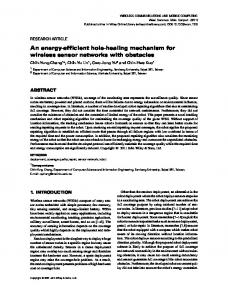
Fig. 1.
Definition of the terms step and task in a workflow
of physical cores available for the VM. Another solution is to use one VM for each task of the workflow. This solution allows to adapt the size of each VM depending on how much resources the current task requires. A VM sizing that fits the needs of each task avoids the waste of computing resources and may decrease the global energy consumption of the Cloud with simple energy optimization techniques, like consolidation and turning off the idle servers. A step can have many tasks and because each task runs in a separate VM, it allows to have a better parallelization than with a single VM. This solution allows to use less resources in the Cloud, improves the execution time of the application [12] and reduce the global electricity consumption of the Cloud.
At the beginning the execution of scientific applications were only on grids and supercomputers, but they are progressively moving to the Cloud [11]. The arising of this kind of applications into the Cloud motivated us to focus on the energy optimization of their execution. A scientific application may execute for days, months or years and the execution can be repeated for a thousand time. The optimization of the energy consumption of one execution can have a significant impact when applied to many applications.
A correct sizing of the VMs allows a better consolidation of the VMs into the Cloud. The consolidation allows to use a fewer number of servers and the unused servers can be powered down, thus reducing the overall energy consumption. In this paper, we propose to give users a control over the sizing of their VM through a single easy-to-use parameter expressing their needs in term of energy-efficiency and performance.
A scientific application is often designed as a workflow which is composed of many steps that represent the different stages of the workflow. Each step has one or many tasks and one task is a single job of the workflow that has to be executed. We talk about mono-task step and many-tasks step. The Figure 1 presents a graphical definition of the terms step and task. This simple application is a workflow with 3 steps. The first step has 1 task (A) like the last step (C), and the second step has two tasks (B and B ’).
A. Data-driven Scientific Applications
The execution of a scientific application into a Cloud requires computing resources. These resources are available through VMs, but the mapping of the workflow into one or many VMs is not done in an automatic manner [12]. A solution is to use a single large VM for the whole workflow. Some tasks may use all the available resources, but some others will require only a portion of these resources. The unused resources could have been used by another VM running into the Cloud. Using only one VM for the application also limits the utilization of the intrinsic workflow’s parallelism. Indeed the parallelization of the application is limited to the number
III.
R ELATED W ORK
It is common for scientific applications to deal with large amounts of data [13]. These data-driven applications can have large input data, a lot of data transfers and may generate a large output (though not necessarily). The way the data is handled in this kind of applications can have a significant impact on the execution time and on the energy consumed by the application. Montage is an example of data-driven application dealing with space images from telescopes in order to generate a mosaic of a space area [14]. Solutions to manage data-driven applications exist. FRIEDA [13] is one of these solutions that handles the preparation of the input data for the execution and moves the generated output after the execution to the location specified by the user. FRIEDA also handles the execution of the task by passing one or many VMs as parameters. Thus FRIEDA is able to parallelize the execution of a task over as many VMs as given in parameters. These solutions focus on the data problem and do not take into consideration the energy problem.
B. Energy-efficiency in Cloud’s Data Centers
A. Assumptions
In 2008, 0.5% of the total world electricity consumption was said to be used by the Cloud [3], this represents between 2% to 10% of the carbon emission [15], [16]. This massive consumption is mainly located in the data centers at the servers’ level. While a server is powered on, it consumes electricity to supply the motherboard, the processors, the harddrives, the memory bars and so on. When a server is not used, all of its components are still electrically supplied and the electrical waste can be high depending on the hardware [4] (typically around 100 Watts for a Dell PowerEdge R720 [17]). Moreover, a 2009 survey [18] showed that on average the data centers have 10% of their servers not used. This waste of energy represents over $19 billion per year and the unnecessary emission of over 11 million tons of CO2 due to their electricity use [18]. Thus, reducing the number of unused powered-on servers can significantly decrease the ecological impact of the Cloud without any performance degradation [4].
In our contribution we assume the following:
Cloud management systems taking the energy into consideration have already been proposed. H. Liu et al. present in their paper [19] a system that does live-migrations of VMs in an optimized manner. This system relying on the notion of dirty pages allows to reduce the shutdown time of the VMs and has a model to calculate the energy consumption of the migration. The algorithm presented in [9] uses VM migrations and the ability to turn on and off the servers in order to reduce the global energy consumption. Another study made by Y. Gao et al. [10] describes a mathematical model to optimize the scheduling of workflow applications into the Cloud depending on deadlines. This model is energy efficient at the cost of dropped requests due to deadline violations. All of these solutions use Cloud features to optimize the energy consumption into the Cloud, but they are not specified for datadriven applications and do not involve directly the users into their energy saving process. S. Tesfatsion et al. present in [20] a system able to adapt the amount of resources given to an application in terms of number of VMs (horizontal scaling), number of CPUs and memory (vertical scaling) and voltage/frequency CPU scaling (hard power scaling). The user gives as input a performance target and an optimal configuration is automatically made to minimize the energy consumption while meeting this performance target. Despite the automatic configuration, the user has to tune 3 parameters to configure the reactivity and the stability of the optimization. This system is complex to configure with its 3 parameters and may deter the users. Our objective is to provide to the user a single lever that allows her to execute her application more or less energy efficiently.
IV.
•
the Cloud Management Platform provides a selection of VM types, each with a fixed amount of computing resources. The VM type is called flavor and goes from the tiny size to the xlarge size. Figure 3 gives a list of the available flavors, inspired by Amazon EC2 [1].
•
startup cost of VMs is not taken into account as the comparison with execution time makes it negligible.
•
a user application is a workflow that can have one or more steps and each step may contain one or more tasks. Each task runs in a separate VM.
•
the user indicates for each step of the workflow how much resources are required for a normal execution. This information is used for the tasks within the step to select the flavor to use for the VM creation.
•
a many-tasks step (presented in Section II) can only contain similar tasks. The tasks may have different input and output data, but the scripts executed by the tasks within a step are identical.
•
once a submitted workflow is accepted (enough available resources), all steps will execute until the end of the application.
B. User Involvement We offer to the user a way to control how her application is executed. This control can be seen as a simple knob that goes from energy efficiency to performance as shown in Figure 2. In energy efficiency mode, less resources are allocated for the execution compared to the resources needed by the application. Less resources imply smaller VMs and thus a better consolidation as VMs are easier to pack together onto physical resources. Less servers are needed to respond to the demand and so, more of them can be switched off. In the performance execution mode, more resources are given to the application than the needed resources. More resources imply bigger VMs and thus decreases the efficiency of the consolidation. To serve the load, more servers are used which implies a greater instantaneous power consumption. However, while the energy efficiency mode is more powerefficient, it is not guaranteed to be more energy-efficient. Indeed, as the VMs allocated to the user are smaller than with the performance mode, they may run for longer, meanwhile potentially resulting in a bigger energy consumption. This will be experimentally evaluated in Section V.
O UR APPROACH
Our goal is to include the user into the energy optimization system by giving her a control over the execution of her application into the Cloud. She can make the execution more energy-efficient or faster. The more energy-efficient the execution is, the more efficient the consolidation. It allows to use a fewer number of servers and thus, reduces the overall energy consumption.
Fig. 2.
User’s easy-to-use knob
In our work we consider 3 execution modes: energyefficiency, normal and performance. Each execution mode is linked to a numerical value: −1 for energy efficiency, 0 for a normal execution and +1 for the performance mode. The normal execution is the mode where the application is
given just the amount of resources it needs for its execution. The two other modes allow to give more or less computer resources to the application. This resources selection is detailed in Section IV-D. C. User’s Application Our study is focused on data-driven workflow applications with sequential and parallel tasks. Each task needs a specific amount of resources in terms of processors, memory and disk space and is executed in a separated VM. The parallel tasks are grouped into steps. In our approach, we consider the parallel tasks as identical. Thus, all parallel tasks in a given step need the same amount of computing resources and their VMs will be of the same size. In order for the user to specify the needed resources information for each step, we defined a workflow description file. It contains, for each step, the amount of needed resources, the size of the parallelization (1 for a mono-task step, 2 and more for a many-tasks step), the program to execute, the location of the input data and also where to move the output data. D. Flavor Selection Each workflow’s task executes in a VM containing a specific amount of resources. It exists different sizes of VM and an algorithm to select the correct VM size depending on the needed resources and the cursor’s value is required. A user that chooses the energy efficient mode executes her application in VMs with less resources than required for optimal performance, while in the performance mode, VMs have more resources than required.
Fig. 3.
Flavor selection mechanism
The Cloud provider (IaaS layer) offers a range of VM sizes that goes from tiny to xlarge. Each of these VM size, called flavor, has a fixed amount of CPU, RAM and disk space resources. A list of the available flavors is shown in Figure 3. As explained in Section IV-C, each task of the user’s workflow needs a specific amount of computer resources. The required resources information of each task allows to find the flavor that has just enough resources. This is the flavor that is chosen when running in normal mode and corresponds to the black 0 in Figure 3. If the cursor is on energy-efficiency, the flavor just under the one chosen for the normal mode is selected (designated with the green −1). Conversely, if the cursor is on performance, the flavor just above the one chosen for the normal mode is selected (designated with the red +1).
Fig. 4.
Server selection mechanism
E. Server Selection A smart placement of the VMs on the servers is important if we want to reduce the overall energy consumption of the Cloud. The idea is to fill as much as possible the servers with VMs and to turn off the unused servers. A fully loaded server, in terms of resources, is a server that consumes the energy efficiently. In contrast, a server that has remaining unused resources corresponds to a server with a bad efficiency [4]. We designated our own VM placement algorithm that we explain using the 3 axes graph shown in Figure 4. Each axis represents a type of resource available on a server: processor resource, memory resource and hard drive resource. One unit on each axis is equal to the amount of resources needed by the tiny flavor. Thus, 1 unit of CPU equals to 1 CPU, 1 unit of RAM equals to 512 MB and 1 unit of disk equals to 5 GB. The triangle filled with the blue color corresponds to the VM we want to create. In the example, we consider a VM that needs 2 units of CPU, 2 units of RAM and 3 units of disk. The other triangles represent the available resources on each server of the Cloud. As an example, the available resources of the Server 1 (the red one) are 4 units of CPU, 3 units of RAM and 3 units of disk. The algorithm works as follows. First, we only select triangles bigger or equal to the blue triangle for each axis. If any triangle goes inside the blue one, it means the corresponding server does not have enough available resources for the VM to be created. Then, rather than selecting a random server for the VM creation, we decided to select the server that fits the most the shape of the blue triangle. Indeed, it allows to optimize the server utilization by allocating as much resources as possible and also keeps the servers with more available resources free for future bigger VM creations. In order to find the server that fits the VM’s shape, we used the following equation which defined the calculation of the ∆ value:
∆ cpu = available cpu − needed cpu ∆ ram = available ram − needed ram ∆ disk = available disk − needed disk ∆ = ∆ cpu + ∆ ram + ∆ disk
(1) (2) (3) (4)
It sums the difference between the needed resources for the VMs and the available resources on each axis. The result is always equal or greater to 0. The server giving the smallest ∆ has the most resources used after the VM creation (ie. its free resources will be the smaller) and thus this server is selected by the algorithm. If many servers are equal to the smallest ∆, another selection has to be made in this subgroup. In this case, the algorithm calculates the number of ∆ to zero for each server in this subgroup. This value is the number of axis that has its ∆ value equal to zero. As an example, if only ∆ cpu = 0, the number of ∆ to zero will be equal to 1. The pseudo-code to calculate this value is presented in Algorithm 1. On Figure 4 example, for Server 4, ∆ cpu and ∆ ram are equal to zero, thus the number of axis where ∆ is equal to zero is 2. A server that has only one axis filled like Server 1 and Server 2 (∆ disk) would not be the best choice, because it makes the creation of another instance impossible and the remaining free resources are more important. In our example, Server 4 is the choice where the server is the most filled. We choose to select the server that has the greatest number of ∆ to zero because it allows a better server’s resources utilization. Algorithm 1 Calculation of the number of ∆ to zero function CALCULATE NB ∆ TO ZERO(host) nb ∆ to zero ← 0 for all axis in host do if ∆ axis = 0 then nb ∆ to zero ← nb ∆ to zero + 1 end if end for return nb ∆ to zero end function In the case where no servers with enough resources are found by the algorithm, the algorithm tries to find a server already turned off with a sufficient amount of resources for the VM to create. The first suitable server found is then turned on and selected for the VM creation. Finally, if no suitable servers are found within the turned on and turned off servers, the algorithm rejects the user’s request and the workflow application terminates with an error status. F. System Architecture The system architecture presented in Figure 5 is designed as follow. The application management service receives from the user the workflow description and the execution trade-off between energy-efficiency and performance. Firstly, it selects the best suitable flavor as described in Section IV-D. Then, the algorithm presented in Section IV-E is executed to select the best suitable server for each VM. Finally, when the VMs are created with the corresponding flavor on the correct server, the workflow execution can start. A specific service manages the execution of each step of the workflow: the data-management
Fig. 5.
Architecture overview
service. This service is focused on data-driven applications. It prepares the input data for each step, executes the program and retrieves the output data to the location given by the user in the workflow description file. The application management service sends a request to the data-management service for the execution of the first step of the workflow. When the execution of the step terminates, another request is sent to start the execution of the second step and so on. When all steps of the workflow have been executed, the final output data is sent back to the user. V.
E XPERIMENTAL VALIDATION
A. Experimental setup In order to validate the energy saving potential of our approach, we conducted an experimental validation. For the Infrastructure-as-a-Service layer, we use OpenStack, a free, open-source and mainstream Cloud computing software platform. It handles the VM creation, deletion and execution. It also provides a service to get the CPU usage of each VM. This last feature is used for the graphs of the experimentation. FRIEDA [13] is a tool developed at the Lawrence Berkeley National Laboratory that corresponds with the DataManagement Service. It prepares the input data for the execution, moves the output data where the user asked for and handles the parallelism of an execution over many VMs. We deploy our system on Grid’5000 [17], a large-scale and versatile test-bed for experiment-driven research with 8,000 cores geographically distributed in 11 sites. We selected the Taurus cluster located in Lyon because it has fine-grained wattmeters. The watt-meters can deliver the power consumption in Watt for each server every second with a 0.125 Watts accuracy. For the experimentation, we created a Cloud with 4 servers, each with 12 cores, 32GB of memory and 598GB of disk space. To load our Cloud system with user’s applications, we designed a data-driven application using Montage. Montage is a toolkit for assembling images into custom mosaics specialized for astronomical images [21]. By giving a space location and a high/width (in angular degrees), it downloads all the images from its servers that match with the given space area. Then it detects the similarities between all images and finally
generates an image of the space area depending on what is known. Montage is modular and we designed our workflow as presented in Figure 6. The first step is composed of 3 parallel tasks that calculate the red, green and blue levels of the images located on the given space area. Then the output of these 3 tasks are moved to the final step (composed of 1 task) that mixes the red, green and blue color levels into a final image. The final image generated by the workflow corresponds to a mosaic of all the images known to be on the space area passed as input. Each task of this workflow executes on a separate VM. Thus there are 3 VMs running in parallel when the workflow starts and then 1 VM running alone for the final step.
Fig. 6. Montage workflow composed of 3 parallel tasks for the first step calculating the red, green and blue color levels and a final step composed of 1 task that mixes the 3 color levels together
For the experiments, we run 2 workflows in parallel. They are both set to the space location called Pleiades, a galactic cluster located in the constellation of Taurus. As for the high/width parameter, there is one workflow with 1 angular degree and the other one with 2 angular degrees. They both start at the same time and calculate an image of the same space location but for a different size. Thus the amount of input data is bigger for the second workflow and it takes longer to execute. When the execution of the workflows starts, the CPU usage of each VM and the power consumption in Watt of each server is recorded until all workflows terminate. The experiment is run five times for each execution mode. One run with both workflow in normal execution mode, then an execution in performance mode and finally one execution in energy efficient mode. The results are presented in Section V-B: first we show one run of the experiment, and then we present a synthetic view of all the runs. B. Results Figure 7 shows the execution results of the two workflows executed in normal mode. The graphic at the top represents the power consumption in Watt of each server. Each server has a different color. The two other graphics represent the CPU usage of the VMs used by each workflow. The color of each VM corresponds to the server where the VM has been hosted. While we have access to the CPU usage per VM, the power consumption is only available for the entire physical server as it is collected from external watt-meters. The power consumption graph shows that only 2 servers has been used to execute the workflows. The unused servers are automatically turned off. This behavior can be seen at time 50. At time 570, server 2 is not used anymore and thus
it is switched off. At the end of the execution, server 1 is also powered down. The workflow Montage 1 calculates the space area for 1 angular degree in contrast to Montage 2 that calculates for 2 angular degrees. It explains why the execution time is shorter for Montage 1. When the experiment starts, the VMs for the three first steps of Montage 1 are created on server 1 (the blue server). Two VMs of Montage 2 manage to be created on server 1 until this one is fully used. The last VM for the step called stepA 2 is created on server 2. When the parallel steps of Montage 1 terminates at time 340, the resources taken by the three VMs can not be freed because of data-transfers purpose. Thus, the VM for the final step needs to be created on server 2. Then the three VMs are deleted at time 360. The same behavior occurs with Montage 2. At time 530 the three VMs terminate their execution, the VM for the final step is created on server 1 because it has enough free resources, data-transfers to the new VM proceed and then the three previous VMs are deleted at time 550. Because there are no remaining VMs running on server 2, the server is power downed in order to save energy. Figure 8 presents the average values obtained after 5 executions of the experiment for each execution mode. In normal execution mode, all VMs of each workflow have the flavor that fits the best their needs in terms of resources. The average power consumption is 247 Watts and the workflows execution time is 791 seconds. In performance execution mode, each VM is given the flavor just above the one that fits their need. Thus the VMs take more resources on the servers and more of them are needed to respond to the load. The use of more servers implies more static energy and thus an increase in the overall power consumption. The power consumption goes up to 329 Watts, which represents an increase of 33% compare to a normal execution. The execution time is shorten by almost 3% (769 seconds instead of 791 seconds). The parallelism of the parallel tasks could be improved in order to have a better use of all the CPU cores. In energy efficiency execution mode, each VM is given the flavor just under the one that fits their needs. The VMs take less resources on the servers and so, less servers are needed to respond to the load. It implies a decrease in the energy consumed by the Cloud. It consumes 188 Watts on average which represents a decrease of 24% compare to a normal execution. The execution time increases of almost 6% (837 seconds instead of 791 seconds). The execution of the workflows takes longer because less resources are available on the VMs. However, overall, this mode is more energy-efficient than the two others. VI.
D ISCUSSION
A. Contributions Our objective was to reduce the energy consumed by the Cloud by taking the user as a main lever to save energy. We restricted our domain of application to scientific data-driven workflow applications. To demonstrate our point, we implemented an Application Management Service that offers the user to select an execution mode when she uploads her workflow. The execution mode can be normal, energy efficiency or
Fig. 7.
Results of an execution of two workflows in parallel (Montage 1 and Montage 2), both in normal execution mode
time. The Cloud consumes up to 33% more energy for a gain in execution time of only 3% compared to a normal execution. B. Limitations
Fig. 8. Average results after 5 executions of the experiment in each execution mode
performance mode. Our prototype implementation runs beside a Data-Management Service called FRIEDA and these two services live on top of the well-known IaaS, OpenStack. For the evaluation, we deployed our prototype on Grid’5000, a French platform for experimenting distributed systems. As a benchmarking application, we selected the Montage workflow. It is a toolkit in the field of astronomy that uses space images to recreate a space area depending on coordinates given as input. We demonstrated that a user who agrees to lose a bit of performance can make a significant decrease in energy consumption. In energy efficient mode, for a loss of around 6% in execution time, the user can save up to 24% in energy consumed in comparison to a normal execution. In contrast, a user that chooses to run in performance mode consumes more energy while making a meaningless improvement in execution
1) More than 3 possible values for user tuning: Currently we offer 3 choices to the user. In our future work, we would like to study a more fine-grained parameter for the users. As an example, with an energy efficient mode going from 0 to −2, the user would be able to select the flavor two steps under the recommended one. However, it is not sure that this new mode will be profitable: it may increase the duration too much for saving energy. 2) Automatic parallelization of the workflows: In the scientific area we often execute our workflows on one single instance. The parallelization of the workflows allows to balance the load and accelerate the execution. However, making this parallelization in an automatic manner is difficult and is a complete research subject [12]. This is why the parallelism design is often done manually. 3) Montage benchmark using all available CPUs: The Montage benchmark does not adapt its execution to the number of available CPUs. Thus giving a flavor with more resources than needed does not improve the execution time as much as it could be. An important update would be to improve the projection stage of the workflow. The solution is to not use the command mProjectExec but mProject instead. mProjectExec goes through all files in a folder and applies the projection on each of them in a sequential way. It is done on a single CPU. Using mProject allows to control the parallelization over many CPUs.
4) Reuse already created Instances: In the current implementation of our system, the required instances at each step are created when the workflow reaches the step. When the instances are created and that the post-installation is terminated, the instances of the previous step are deleted. If the previous step had one or more instances with the same flavor as the one required for the current step, these instances could have been reused. It would avoid the time required for the instance creation but also avoid a new submission of resource allocation and may also avoid the turning on of a new host and the data transfer among the VMs. 5) Design incentive economic models: Our system allows to save energy when the user accepts to lose in performance. However, why would she choose to lose in performance if she does not gain anything in return? A possible solution is to design an incentive economic model. This model could take into consideration the additional electrical cost caused by a performance run and the gain obtained by an energy efficient execution. A pricing system based on a carbon tax for instance could force the user to pay more if she chooses performance. If she chooses energy efficiency, this model could offer green tokens that give the user free access to some resources for a given time. VII.
C ONCLUSION AND FUTURE WORK
In this paper, we propose a set of mechanisms that offers to the user an easy way to act on the energy-efficiency of her scientific application deployed on the Cloud. Through an experimental validation, we show that substantial amounts of energy can be saved by using smaller VMs to run typical applications. These smaller VMs are indeed easier to allocate onto physical servers already running VMs. Our prototype implementation also shows the feasibility of this approach. This work shows the potential benefits of involving users into energy-efficient management systems of Cloud infrastructure. Our future work includes the computation of a rough estimate of the energy used by each mode which will be displayed to the user in order to increase its energy-awareness. We also plan to run larger experiments involving more users and playing with the percentage of energy-aware users in order to study the influence of this percentage over the Cloud’s energy consumption.
Office, Computation Technologies Project, under Cooperative Agreement Number NCC5-626 between NASA and the California Institute of Technology. R EFERENCES [1] [2] [3] [4]
[5]
[6]
[7]
[8]
[9]
[10]
[11]
[12]
[13]
[14] [15]
ACKNOWLEDGMENTS This research uses FRIEDA developed by the Data Science and Technology Department at Berkeley Lab. The authors would like to thank Devarshi Ghoshal, Deb Agarwal, Lavanya Ramakrishnan and the FRIEDA’s team for their help and useful comments on this work. Experiments presented in this paper were carried out using the Grid’5000 experimental test-bed, being developed under the INRIA ALADDIN development action with support from CNRS, RENATER and several Universities as well as other funding bodies (see https://www.grid5000.fr). This research also makes use of Montage. It is funded by the National Science Foundation under Grant Number ACI1440620, and was previously funded by the National Aeronautics and Space Administration’s Earth Science Technology
[16] [17] [18] [19]
[20]
[21]
“Amazon EC2,” http://aws.amazon.com/ec2/. W. Forrest, J. Kaplan, and N. Kindler, “Data centers: How to cut carbon emissions and costs,” McKinsey report, Dec. 2008. J. Koomey, Growth in data center electricity use 2005 to 2010. Oakland, CA: Analytics Press, 2011. A.-C. Orgerie, M. D. d. Assunc¸ao, and L. Lef`evre, “A Survey on Techniques for Improving the Energy Efficiency of Large-scale Distributed Systems,” ACM Computing Surveys, vol. 46, no. 4, pp. 47:1–47:31, Mar. 2014. A. Bohra and V. Chaudhary, “VMeter: Power Modelling for Virtualized Clouds,” in IEEE International Symposium on Parallel Distributed Processing (IPDPSW), Apr. 2010, pp. 1–8. M. Haque, K. Le, I. Goiri, R. Bianchini, and T. Nguyen, “Providing green SLAs in High Performance Computing clouds,” in Green Computing Conference (IGCC), International, June 2013, pp. 1–11. S. Islam, K. Lee, A. Fekete, and A. Liu, “How a Consumer Can Measure Elasticity for Cloud Platforms,” in ACM/SPEC International Conference on Performance Engineering (ICPE), 2012, pp. 85–96. A.-C. Orgerie, L. Lefevre, and J.-P. Gelas, “Save Watts in Your Grid: Green Strategies for Energy-Aware Framework in Large Scale Distributed Systems,” in IEEE International Conference on Parallel and Distributed Systems (ICPADS), Dec 2008, pp. 171–178. X. Zhu, H. Chen, L. Yang, and S. Yin, “Energy-Aware Rolling-Horizon Scheduling for Real-Time Tasks in Virtualized Cloud Data Centers,” in IEEE International Conference on High Performance Computing and Communications, Nov 2013, pp. 1119–1126. Y. Gao, Y. Wang, S. K. Gupta, and M. Pedram, “An Energy and Deadline Aware Resource Provisioning, Scheduling and Optimization Framework for Cloud Systems,” in IEEE/ACM/IFIP International Conference on Hardware/Software Codesign and System Synthesis, ser. CODES+ISSS ’13, 2013, pp. 31:1–31:10. C. Hoffa, G. Mehta, T. Freeman, E. Deelman, K. Keahey, B. Berriman, and J. Good, “On the Use of Cloud Computing for Scientific Workflows,” in IEEE International Conference on eScience, Dec 2008, pp. 640–645. W. Chen, R. Ferreira da Silva, E. Deelman, and T. Fahringer, “Dynamic and Fault-Tolerant Clustering for Scientific Workflows,” IEEE Transactions on Cloud Computing, vol. PP, no. 99, pp. 1–1, 2015. D. Ghoshal and L. Ramakrishnan, “FRIEDA: Flexible Robust Intelligent Elastic Data Management in Cloud Environments,” in SC Companion: High Performance Computing, Networking Storage and Analysis (SCC), ser. SCC ’12, 2012, pp. 1096–1105. “Montage,” http://montage.ipac.caltech.edu/. Gartner, “Gartner Estimates ICT Industry Accounts for 2 Percent of Global CO2 Emissions,” http://www.gartner.com/newsroom/id/503867, 2007. M. Mills, “The Cloud Begins With Coal - Big Data, Big Networks, Big Infrastructure, and Big Power,” Digital Power Group, Aug. 2013. “Grid’5000,” https://www.grid5000.fr. “Unused Servers Survey Results Analysis. Green Grid report,” Green Grid report, 2010. H. Liu, C.-Z. Xu, H. Jin, J. Gong, and X. Liao, “Performance and Energy Modeling for Live Migration of Virtual Machines,” in International Symposium on High Performance Distributed Computing (HPDC), ser. HPDC ’11, 2011, pp. 171–182. S. Tesfatsion, E. Wadbro, and J. Tordsson, “A combined frequency scaling and application elasticity approach for energy-efficient cloud computing,” Sustainable Computing: Informatics and Systems, vol. 4, no. 4, pp. 205 – 214, 2014. G. B. Berriman, E. Deelman, J. Good, J. Jacob, D. S. Katz, C. Kesselman, A. Laity, T. A. Prince, G. Singh, and M. hu Su, “Montage: A grid enabled engine for delivering custom science-grade mosaics on demand,” in SPIE conference 5487: Astronomical Telescopes, 2004.