Energy Source Lifetime Optimization for a Digital System through Power Management Manish Kulkarni and Vishwani D. Agrawal Department of Electrical and Computer Engineering Auburn University Auburn, AL 36849
[email protected],
[email protected] Abstract—We examine the energy consumption of a digital circuit with voltage scaling and observe its impact on the energy efficiency of the battery. We study the system with a power source under throughput constraints and we propose a method to find a right size of battery to satisfy given system requirements. For systems with limit on battery weight or volume, we suggest a right circuit voltage operating point. Maximizing battery lifetime, expressed in terms of clock cycles, depends upon a proper choice of the supply voltage and the corresponding clock frequency that the circuit would support. Analysis of various battries shows that when no system performance requirement is specified, the optimum operating supply can be in the subthreshold range.
I. I NTRODUCTION Every processor chip has a physical limit on power dissipation it can support. For systems that use these processors, performance and power become opposing requirements. Modern computing systems, therefore, have built-in power control schemes. For example, thermal sensors on a processor chip may trigger a slowdown of the processor clock [2]. There are various factors which force designers to consider low power as one of the main goals. More and more transistors are being packed into a single core, and more cores per chip, as the scale of integration improves. This leads to steady growth of operating frequency and processing capacity per chip, resulting in increased power dissipation. Since present generation devices are at a safe distance from reaching their fundamental physical limits, the evolution would continue for a while. Another factor that fuels need for low power chips is the increased market demand for Mobile Internet Devices (MIDs) powered by batteries. Batteries have not experienced a rapid density growth. The specific weight (stored energy per unit weight) of batteries barely doubles in several years [25] as shown in Figure 1. Also, further increase in battery specific weight will create concerns about their safety as the energy density will approach that of explosive chemicals. So battery technology is not going to solve the power problem in near future. For mobile systems, energy consumption and the rate of consumption (power) are directly related to the battery capacity. Higher discharge rate reduces the capacity, requiring bulkier batteries with higher current rating [4] or more frequent recharging. Thus, it is important to control the power consumption. For MIDs, consideration of a suitable metric is also important since the ultimate aim is to achieve maximum battery lifetime or more operations per recharge. Traditional metrics like power and energy are not sufficient to evaluate systems which operate on batteries. This paper aims to summarize current state of battery models and various power source optimization methods. We also propose two Reprinted from Proc. IEEE International Conf. Industrial Technology and 43rd IEEE Southeastern Symp. System Theory, Auburn, AL, March 14-16, 2011.
Fig. 1.
Growth in energy densities of Lithium-ion batteries.
methods to optimize source energy and obtain maximum number of operations per recharge. II. BACKGROUND A. Overview of Battery Modelling Battery modelling, a mathematical description of batteries, is an important part of battery design and battery related system design. Several types of battery models have been reported in the literature. Use of any particular model is decided by its suitability in the application. For instance, a physical model may be suitable to construct a battery, whereas an abstract or analytical model is suitable for designing a system containing batteries and optimization of battery parameters for the system. We briefly discuss different types of models here. Physical models [7], [8], [10] are the most accurate in describing battery’s physical parameters. However, they are also the slowest to produce predictions and the hardest to configure. These models may need many parameters such as structure, chemical composition, temperature etc. for their configuration. Empirical models are the easiest to configure, and they quickly produce predictions, but they generally are the least accurate. Peukert’s law [6] and battery efficiency model proposed by [12] are examples of empirical models. Instead of modelling discharge behaviour, abstract models attempt to provide an equivalent representation of a battery. Although the number of parameters is not large, such models employ lookup tables that require considerable effort to configure. PSpice models by [9], [16], electrical model by [14], discrete time model in VHDL by [17], and an accurate electric model by [13], which we use for evaluation of system impact on battery efficiency, are few examples to mention. An excellent summary of various battery models is given by Rao et al. [6] B. Power Source Optimization Methods 1) Voltage Management Methods: Most common of voltage management methods is dynamic voltage scaling (DVS). Here the circuit can statically or dynamically vary VDD depending on the throughput requirement. A relevant problem is to find
C. Choice of Metric Traditional metrics like minimization of power and energy are not quite relevant when power source (battery) optimization is a concern. The energy stored in a battery is assumed to be constant and available at any possible rate. In reality, however, the energy stored in a battery may not be used to its full extent. The delivery of energy from battery to system depends on the average value of the current drawn from the battery. Battery lifetime does not have a simple linear relationship with power consumption of the circuit. e.g. a 2X increase in system power can cause a 3X decrease in battery lifetime. These facts motivate us to consider other metrics for design goal of power source optimization. Weiser et al. [18] present Millions of Instructions Per Joule(MIPJ) as a quality metric for dynamic voltage scaling (DVS). The key idea is to eliminate idle time by reducing the processor voltage and clock for a given segment of computation. To predict processor utilization, either a fixed-size window of events in future or a fixed-size window of events in the past is analyzed, and the corresponding DVS decisions are evaluated using trace-based simulations. This method has limited practicality since measurement and tracking of battery energy in terms of joules is difficult. Rakhmatov et al. [19], [20] use an analytical model of the battery to minimize a cost function σ(t). This cost is function of load current i(t) and sum of l(t) and u(t), where, l(t) is
RSeries R Transient_S R Transient_L
+ −
I Batt
Battery lifetime
Fig. 2.
VOC (VSOC )
C Capacity
VSOC (0−1 volt) RSelf−Discharge
an optimum value of supply voltage which would minimize the energy consumption of the battery and still maintain the required throughput. [12] propose a method to find optimum operating voltage for minimization of battery discharge-delay product. Multi-voltage domain designs can also be classified under this category. Our proposed technique of voltage scaling falls into this category and, in section III, we discuss this technique in detail. 2) Throughput Management Methods: Dynamic frequency scaling is one of the most used methods in this category. CPU frequency scaling for battery powered computers is examined in [15] in terms of its impact on battery life, system performance, and power consumption. Frequency scaling approaches use information from a battery model to vary the clock frequency of system components dynamically at run time. They also use workload characteristics such as runtime and idle-time percentages dynamically, and models of system power and performance. These approaches can be used to ensure efficient use of the battery without significantly compromising system performance [21]. 3) Functional Management Methods: In most cases, a given problem can have an alternate design or implementation method that consumes less power. Some of the low power design techniques such as low power FSM design, bus encoding, gate reordering and battery aware dynamic task scheduling [20] represent few such cases. These methods focus on power management of the system in order to reduce the average current drawn from the battery. A recently proposed functional management method, named instruction slowdown [23], exploits idleness in a pipeline processor to dynamically manage power to different units. Dynamic voltage and frequency scaling (DVFS) is a method that combines voltage and throughput management whereas architecture level parallelism with multicore designs is a combination of all the three methods mentioned above.
+ + −
C Transient_S C Transient_L VBatt VSense = 0 volt − +
I Batt
−
Voltage−current characteristics
An Electrical Model for Lithium-ion battery.
the charge lost in load and u(t) is the charge unavailable. Evaluation of this cost function is in the context of DVS for task scheduling and battery optimization. Minimization of this cost function is subjected to constraints such as task dependencies, task deadlines etc. Pedram et al. [12] propose battery discharge-delay product as the metric. This metric is similar to the energy-delay product while accounting for the battery characteristics and the DC/DC conversion efficiency. The BD-delay product states that the design goal should be to minimize delay and maximize battery lifetime at the same time. We consider clock cycles per recharge as a metric for evaluation of optimization methods. This metric is particularly suitable for DVFS since with voltage scaling the operating frequency changes and system now takes longer or shorter time to finish the task. A relevant measure of lifetime, therefore, is the lifetime in number of clock cycles. Thus, instead of expressing the lifetime in raw seconds, we express it in terms of computational work units. III. A VOLTAGE MANAGEMENT METHOD A. Battery Model Used for This Work As mentioned before, we use an electrical model provided by [13]. This model is shown in Figure 2. One of the reasons behind choosing this model is its capability of predicting lifetime and I-V performance. Besides load current, it considers effects of temperature, number of cycles and storage time dependence of capacity on battery lifetime. This model is also scalable as it models batteries of varying AHr ratings and predicts runtime for different load current profiles. This model can be used for Lithium-ion, polymer Lithium-ion and NiMH batteries. 1) Description: On the left side of figure 2, a capacitor CCapacity represents the present state of charge (SOC) of the battery and a current source IBatt models the discharge. The right side of the circuit models the voltage and current characteristics of the battery based on the current drawn from the battery. These two parts are connected to each other by a voltage controlled voltage source VSOC whose value depends on the open circuit voltage(VOC ) of the capacitor CCapacity Assuming a battery is discharged from an equally charged state to the same end-of-discharge voltage, the extracted energy, called usable capacity, declines as cycle number, discharge current, and/or storage time (self-discharge) increases, and/or as temperature decreases [13]. The usable capacity can be modelled by a full-capacity capacitor (CCapacity ), a selfdischarge resistor (RSelf −Discharge ), and an equivalent series resistor (the sum of RSeries ,RT ransientS , and RT ransientL ). The full-capacity capacitor CCapacity represents the whole charge stored in the battery, i.e., SOC, by converting nominal
4.2V to 3.5V for Li−ion battery
battery capacity in Ahr to charge in coulomb and its value is defined as, CCapacity = 3600 × Capacity × f1 (Cycles) ×f2 (T emp)
(1)
VOC (SOC) = −1.031e−35×SOC + 3.685 + 0.2156 ×SOC − 0.1178 × SOC 2 + 0.3201 × SOC 3
(2)
RSeries (SOC) = 0.1562e−24.37×SOC + 0.07446
(3)
RT ransient
S (SOC)
RT ransient
= 0.3208e−29.14×SOC + 0.04669
(4)
= −752.9e−13.51×SOC + 703.6
(5)
= 6.6038e−155.2×SOC + 0.04984
(6)
= −6056e−27.12×SOC + 4475
(7)
S (SOC)
CT ransient
L (SOC)
CT ransient
L (SOC)
DC to DC voltage Decoupling capacitor converter
Battery
where Capacity is the nominal capacity in AHr, f1 (Cycle) is a correction factor for number of cycles, f2 (Temp) is a temperature-dependent correction factor. 2) Battery Lifetime: The state of charge (SOC) is defined as 1.0 for a fully charged battery. It is represented by a voltage VSOC , which ranges between 0 and 1 volt. The charge of the battery is stored in a capacitor CCapacity whose value is determined as indicated by Equation 1. Thus, 1 AHr × 3600 seconds is the total amount of charge in coulombs. As the battery goes through cycles of charging and discharging its capacity to hold charge is affected, reducing the usable capacity. That is represented by f1(Cycles). Similarly, temperature affects the usable capacity and that is represented by f2(Temp). For simplicity, we have assumed both factors to be unity in the present discussion. The resistance RSelf Discharge represents leakage when the battery is stored over a long period. For reasonable time between recharge, this can be considered to be large or practically infinite. The current source IBatt represents a source when the battery is being charged or a load when the battery is powering a circuit. In the latter case, it is the current being supplied to the DCto-DC converter and to the circuit after conversion. When the model is used to simulate the behavior of a battery that is fully charged, VSOC is initialized to 1 volt. 3) Voltage and Current Characteristics: The circuit on the right in Figure 2 emulates the terminal voltage of the battery as it supplies current. This part is linked to the part on the left by state of charge (SOC), a quantity in the (0.0, 1.0) range. VOC (SOC) is the open circuit voltage. For Lithiumion batteries, Chen and Rincon-Mora [13] empirically derive expressions for the circuit components, which all depend on SOC.
B. Problem Statement A typical power supply for an electronic system is shown in Figure 3. The primary source of energy is a battery, normally an electrochemical device [1]. The battery can be a primary type that is discarded after it is discharged, or a rechargeable type. As shown in Figure 3, a fully charged Lithium-ion battery supplies 4.2 volts and when the voltage drops below 3.0 volts it is recharged. The electronic system
VDD Electronic system
GND Fig. 3.
Powering an electronic circuit.
is supplied a voltage VDD that is close to 1 volt or lower for modern nanometer technologies. A DC-to-DC converter [22], [12] provides the voltage transformation as well as the capability to vary VDD for power management. Because the current requirement of the electronic system is often pulsed and time varying, decoupling capacitors are used to smooth the transient ripples. The decoupling capacitors can be external or distributed, in general, in the power grid of the system. The size of a battery is specified in terms of the electrical charge it can supply. A Lithium-ion battery of 400mAHr can supply 400mA for one hour. It will supply 200mA for two hours. While 400mA is the rated current for this battery, up to three times the rated current or 1.2A can be drawn for a duration of 20 minutes. However, a discharge rate higher than this can cause noticeable loss in the internal impedance of the battery resulting in heating. This results in a loss of efficiency as defined below. The time for which a fully charged battery can supply current before requiring recharge is called its lifetime. Thus, Ideal Lif etime =
AHr rating Load Current in Amperes
(8)
The end of lifetime is indicated by significant drop in the terminal voltage. Thus, the end of lifetime for a 4.2 volt Lithium-ion battery is indicated by a drop in terminal voltage below 3 volts. In practice, a battery can maintain an ideal lifetime for load currents smaller than three times the rated current. Thus, a 400mAHr battery can supply up to 1.2A current. For higher currents, there is generally a reduction in actual lifetime due to internal losses. Therefore, Ef f iciency =
Actual lif etime Ideal Lif etime
(9)
The problems we address are [24]: 1. Determine the minimum voltage supply VDD for a synchronous clocked digital system that will meet the performance (critical path delay) requirement. Obtain the load current for the battery. 2. Determine the minimum battery size (efficiency ≥ 85%) for the required load current. The lifetime of the minimum size battery will be 20 minutes. Determine the battery size for given recharge interval. 3. For the selected size of the battery, we determine a low performance energy saving supply voltage VDD for which the lifetime of the battery in clock cycles is maximized. We examine these problems under various system constraints as described by following cases: • Case I: System is performance bound • Case II: Battery size or weight is a primary concern
−4
1
10
10
4
Delay Battery Current −5
0
10
−1
10
−7
−2
10
10
−8
10
−9
0.1
3.4 3.2 3
−3
10
10
3.6
VBatt (volts)
Delay (s)
−6
10
Battery Current, IBatt (A)
10
Battery Capacity = 1.2AHr IBatt= 3.6A
3.8
2.8 2.6
−4
0.2
0.3
0.4
0.5
0.6
0.7
0.8
0.9
1
10
VDD (volts)
2.4 2.2
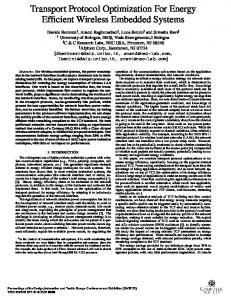
Fig. 4. Circuit delay and current versus VDD obtained from HSPICE simulation.
We consider a case where the system has to meet a certain throughput requirement. We analyze these problems and propose a step wise solution to find a matching battery for an electronic system [24]: 1) Step 1: Determine circuit characteristics: For understanding the effects of voltage scaling on battery efficiency, we consider a 70 million gate hypothetical system. We assume that the critical path consists of a 32-bit ripple-carry adder consisting of 352 NAND gates. The technology assumed is 45 nanometer bulk CMOS. For simulation, the predictive technology model (PTM) is used [3], [5]. The 32-bit adder was simulated using the HSPICE simulator [11]. We determined the critical path delay of the 32-bit adder for VDD ranging from 1.0V to 0.1V at interval of 0.1V, as shown in Figure 4. We found that the although the circuit slows down by more than three orders of magnitude, it works correctly upto VDD = 0.1V , which is below the threshold voltage of 0.292V for the 45nm PTM devices [5]. Next, to determine the average current we simulated the circuit using 100 random vectors. The simulation was repeated for all the same values of VDD as before. In each case, vectors were applied at an interval equal to the corresponding critical path delay. Assuming a similar activity for the entire 70 million gate system, the average current measured for the 352-gate adder from Hspice simulation was multiplied by 200,000. Considering a 100% efficiency DC-to-DC converter that translates VDD to the 4.2V rated terminal voltage of Lithium-ion battery, we determine the battery load current IBatt by multiplying the circuit current by VDD/4.2. That IBatt as a function of VDD is shown in Figure 4. Now, as mentioned in the problem statement, we determine the operating voltage of the circuit based on the throughput requirements. If the circuit needs to work at 200MHz, then from Figure 4, the operating voltage is 0.6 V and the corresponding current drawn from the battery is 477mA. 2) Step 2: Determine smallest battery size: The model of the selected battery type is simulated for various current loads obtained in the previous step. Using the load current, scaled for the ratio of battery voltage to circuit VDD, the battery model is simulated to determine the terminal voltage as a function of time. In practice, this scaling is achieved by a DC-to-DC converter that is known to have high conversion efficiency (greater than 90%) [17], [12]. The time between the fully charged state to the fully discharged state gives the battery
200
400
600
800
1000
1200
Time (seconds)
Fig. 5. VBatt vs. time when a battery of 1.2 AHr capacity is subjected to load current, IBatt = 3.6A. 120
Battery Load Current, I Batt
100
Battery Efficiency (%)
C. Case I: System is performance bound
0
0.6 A 1.2 A 1.8 A 2.4 A 3.0 A 3.6 A 4.2 A 4.8 A 5.4 A 6.0 A
80
60
40
20
0
0
1
2
3
4
5
6
Battery size (N) (For N=1, Battery Capacity= 400mAHr)
Fig. 6.
Battery efficiency versus battery size for various load currents.
lifetime in time units (seconds). This is repeated for increasing battery sizes, normalized with respect to the smallest unit. A lower bound on battery size is determined for a minimum of 85% efficiency. While the selected battery should not be smaller, its actual size is determined by the recharge interval requirement of the system. We assume the use of Lithium-ion batteries with a unit battery (N = 1) of 400mAHr rating. As an example, consider the battery load current IBatt = 3.6A for VDD = 0.9V in Figure 4. Figure 5 shows the battery terminal voltage VBatt obtained from HSPICE [11] simulation of the battery model of Figure 2. In this Figure, the battery size is N = 3, i.e., Capacity = 1.2AHr. The leakage resistance, usually very large, was taken as 1 gigaohms. All other parameters of the battery model have been described in subsection III-A Figure 6 shows the battery efficiencies obtained in this way for various battery sizes and for varying load currents. We observe: 1. When the load current is small compared to the AHr rating, the efficiency is 100% or higher. For example, for a battery of size N = 5 (2AHr) the efficiency for IBatt = 0.6A is 107%. 2. When the load current is large compared to the AHr rating, the efficiency can be significantly lower. The 85% line is shown to indicate that a power source with lower efficiency may be considered unacceptable. For any given load current this 85% line allows us to determine the smallest battery that can be used.
Fig. 7. Simulation of a 400 mAHr battery for a range of supply voltages (VDD).
Fig. 8. Battery lifetimes in clock cycles as a function of chip voltage for 400 mAHr and 1600 mAHr batteries.
Continuing further with our example from Step 1, with a current of 477 mA and an efficiency of ≥ 85%, a battery of size 400 mAHr is chosen. Now this battery is simulated for entire range of voltages and then a graph of supply voltage versus number of cycles per recharge is plotted as shown in Figure 7. This graph indicates that as we move towards right from the dotted line at 0.6 V, the circuit throughput increases and battery efficiency decreases, while moving towards left increases the battery lifetime (until the dotted line at 0.3 V) decreasing throughput. 3) Step 3: Meeting the lifetime requirement: While the smallest size battery has advantages of weight and cost, it can provide a lifetime (time between recharges) which may not be sufficient. Figure 4 is used to determine the battery current IBatt for given performance requirement. Again, continuing with our previous example, consider the system has a battery lifetime requirement of 3 hours. From Figure 6, the minimum size battery i.e. 400 mAHr (N = 1) gives 98% efficiency and hence the lifetime is 3600 × 0.98 × 0.4/0.477 = 2952 seconds. To meet the requirement of 3 hours, i.e 10800 seconds, We, therefore, use the battery size of N = 10800/2952 = 3.658 ≈ 4. So we select a battery of 1600 mAHr. Number of cycles obtained per recharge with these batteries is as shown in Figure 8. 4) Step 4: Determine minimum energy modes: The previous step determines two battery sizes, namely, the smallest usable
Fig. 9. Battery lifetimes in clock cycles as a function of chip voltage for 400 mAHr and 1600 mAHr batteries.
battery that meets the performance requirement and another size that can meet both performance and recharge interval requirements. We now determine maximum lifetime modes for each battery. In this mode, the performance requirement is completely relaxed and the supply voltage (VDD) is determined for maximum lifetime in clock cycles. For some nanometer technologies, this VDD can be below the subthreshold voltage [26]. Most electronic systems have performance and uninterrupted operation requirements that determines the battery size as discussed above. But, a system does not always operate in the maximum performance environment. Lowering VDD, that can be easily done by the DC-to-DC converter, reduces IBatt and hence extends the battery lifetime. Critical path delay, however, increases and clock frequency must be reduced. A relevant measure of lifetime, therefore, is the lifetime in number of clock cycles. Thus, instead of expressing the lifetime in raw seconds, we express it in terms of computational work units. Figure 9 shows the lifetime in clock cycles as a function of VDD for the two batteries of Table I. According to Figure 4, the critical path delay for VDD = 0.3V is 0.2s, giving a clock frequency of 5MHz. The high performance mode and the minimum energy modes are summarized in Table I. The minimum energy mode increases the time between recharges by thousand fold. That is misleading because the clock frequency is reduced 100 times. However, it does provide more than two fold increase in the number of clock cycles per battery recharge. D. Case II: Battery size or weight is a primary concern Some applications call for a special set of requirements from the circuit due to a stringent limit on battery size and weight. Applications such as bio-implantable devices, wearable computing devices, hearing aid cannot exceed a certain volume or weight of the battery. Such devices often do not have very high performance requirements. These devices make use of lithium ion batteries which are light weight, have high energy density and are less bulky. One such popular battery is CR2032(CR) and its properties are as described below. Note that even though the battery rating is 225 mAHr, the maximum current that the batter can provide is only 3 mA.
TABLE I H IGH PERFORMANCE AND MINIMUM ENERGY MODES OF OPERATION .
Battery size N AHr 1 0.4 4 1.6
200MHz, V DD = 0.6V Eff. Lifetime % sec. cycles 98 3000 619 × 109 103 12300 2540 × 109
Fig. 10. Battery lifetimes in number of clock cycles for CR2032 with max. Ibattery = 3mA.
CR2032 Lithium ion battery: • Nominal Voltage: 3V • Capacity: 225mAHr • Nominal Current: 0.3 mA • Maximum Current: 3 mA A four step analysis, similar to that explained for the previous case, can be carried out for this case. Simulation of the above mentioned CR2032(CR) battery is shown in Figure 10. It is clear from Figure 10 that though ideal battery can keep providing higher number of cycles for voltage ≥ 0.3 V, practically it would have lower efficiency since the maximum current battery can supply is only 3 mA. IV. C ONCLUSION This work provides an insight into the power source optimization techniques. We present a broad categorization of optimization techniques and propose voltage management methods for maximizing power source energy efficiency. We demonstrate how a power source is selected to economically satisfy the operational requirements of a system. An electrical model of a battery allows the determination of its lifetime and efficiency. Lifetime measured in terms of clock cycles is shown to be a useful measure. Simulation of the battery as well as that of the circuit being powered allows determination of high performance and minimum energy operational modes. Other applications of battery analysis may be in assessing and optimizing the power management techniques. Given the size of the battery, its efficiency reduces for higher currents. While power reduction is necessary from temperature and other environmental requirements of semiconductor chips, the influence of power reduction on battery lifetime is important for portable devices. R EFERENCES [1] D. Linden and T. Reddy, “Handbook of Batteries”, 3rd Edition. McGrawHill, 2001
Eff. % > 100 > 100
5MHz, V DD = 0.3V Lifetime sec. cycles 414 × 103 1660 × 109 1364 × 103 6630 × 109
[2] W. Wolf, “Cyber-Physical Systems”, Computer, vol. 42, no. 3, pp. 8889, Mar. 2009. [3] http://www.eas.asu.edu/ptm. [4] I. Buchmann, “Batteries in a Portable World: A Handbook on Rechargeable Batteries for Non-Engineers”, Richmond, British Columbia: Cedex Electronics, Inc., second edition, 2001. [5] W. Zhao and Y. Cao, “New Generation of Predictive Technology Model for Sub-45nm Early Design Exploration”, IEEE Transactions on Electron Devices, vol. 53, pp.2816-2823, Nov. 2006. [6] R. Rao, S. Vrudhula, and D. N. Rakhmatov, “Battery Modeling for Energy-Aware System Design”, Computer, vol. 36, no. 12, pp. 77-87, Dec. 2003. [7] M. Doyle, T. F. Fuller, and J. Newman, “Modeling of Galvanostatic Charge and Discharge of the Lithium/Polymer/Insertion Cell”, J. Electrochemical Soc., vol.140, no. 6, 1993, pp. 1526-1533. [8] T. F. Fuller, M. Doyle, and J. Newman, “Simulation and Optimization of the Dual Lithium Ion Insertion Cell”, J. Electrochemical Soc., vol. 141, no. 1, 1994, pp. 1-10. [9] S. C. Hageman, “PSpice Models Nickel-Metal-Hydride Cells”, EDN Access, 2 Feb. 1995; www.reedelectronics.com/ednmag/ archives/1995/020295/03di1.htm. [10] J.S. Newman, “FORTRAN Programs for Simulation of Electrochemical Systems, Dualfoil.f Program for Lithium Battery Simulation”; www.cchem.berkeley.edu/ jsngrp/fortran.html. [11] Synopsys, Inc., “HSPICE The Gold Standard for Accurate Circuit Simulation”, www.synopsys.com/Tools/Verification/AMSVerification/ CircuitSimulation/HSPICE/Documents/hspice ds.pdf. [12] M. Pedram and Q. Wu, “Design Considerations for Battery-Powered Electronics”, Proc. 36th ACM/IEEE Design Automation Conference, 1999, pp. 861-866. [13] M. Chen and G. A. Rincon-Mora, “Accurate Electrical Battery Model Capable of Predicting Runtime and I-V Performance”, IEEE Transactions on Energy Conversion, vol. 21, no. 2, pp. 504-511, June 2006. [14] H. J. Bergveld, W. S. Kruijt, and P. H. L. Notten, “Electronic- Network Modeling of Rechargeable NiCd Cells and Its Application to the Design of Battery Management Systems”, J. Power Sources, vol. 77, no. 2, 1999, pp. 143-158. [15] T. L. Martin, “Balancing Batteries, Power and Performance: System Issues in CPU Speed-Setting for Mobile Computing”, PhD thesis, Department of Electrical and Computer Engineering, Carnegie Mellon University, 1999. [16] S. Gold, “A PSPICE Macromodel for Lithium-Ion Batteries”, Proc. 12th Ann. Battery Conf. Applications and Advances, 1997, pp. 215-222. [17] L. Benini, G. Castelli, A. Macci, E. Macci, M. Poncino, and R. Scarsi, “Discrete-time battery models for system-level low-power design”, IEEE Trans. VLSI Systems, vol. 9, no. 5, pp. 630-640, Oct. 2001. [18] M. Weiser, B. Welch, A. Demers, and S. Shenker, “Scheduling for Reduced CPU Energy”, Proc. OS Design and Implementation, 1994. [19] D. N. Rakhmatov and S. B. K. Vrudhula, “An Analytical High-Level Battery Model for Use in Energy Management of Portable Electronic Systems”, Proc. IEEE/ACM Intl Conf. Computer-Aided Design, 2001, pp. 488-493. [20] D. Rakhmatov, S. Vrudhula, and C. Chakrabarti,“Battery-Conscious Task Sequencing for Portable Devices Including Voltage/Clock Scaling”, Proc. 39th Design Automation Conf., 2002, pp. 189-194. [21] K. Lahiri, S. Dey, D. Panigrahi, and A. Raghunathan, “Battery-Driven System Design: A New Frontier in Low Power Design”, Proc. Asia South Pacific Design Automation Conf. and Int. Conf. on VLSI Design, Jan. 2002, p. 261. [22] L. Benini, G. Castelli, A. Macii, E. Macii, M. Poncino, and R. Scarsi, “A Discrete-Time Battery Model for High-Level Power Estimation”, Proc. Conf. Design, Automation and Test in Europe, Mar. 2000, pp. 35-41. [23] M. Kulkarni, “Energy Source Lifetime Optimization for a Digital System through Power Management”, MS Thesis, Auburn University, Dec. 2010. [24] M. Kulkarni and V. D. Agrawal, “Matching Power Source to Electronic System: A Tutorial on Battery Simulation”, Proc. VLSI Design and Test Symposium, July 2010. [25] J. Rabaey, “Low Power Design Essentials”, Springer, 2009. [26] A. Wang, B. H. Calhoun, and A. P. Chandrakasan, “Sub-Threshold Design for Ultra Low-Power Systems”, Springer, 2006.