Enhanced Virtual Synchronous Generator Control for Parallel Inverters in Microgrids
Jia Liu1, Yushi Miura1, Hassan Bevrani2 and Toshifumi Ise1 1. Osaka University 2. University of Kurdistan
IEEE Transactions on Smart Grid vol. 8, no. 5, pp. 2268–2277, September 2017 DOI: 10.1109/TSG.2016.2521405
This is a post-print version of an article published by IEEE. The final publication is available at IEEE Xplore via http://ieeexplore.ieee.org/document/7401122/
(c) 2016 IEEE. Personal use of this material is permitted. Permission from IEEE must be obtained for all other uses, including reprinting/ republishing this material for advertising or promotional purposes, creating new collective works for resale or redistribution to servers or lists, or reuse of any copyrighted components of this work in other works.
Enhanced Virtual Synchronous Generator Control for Parallel Inverters in Microgrids Jia Liu, Student Member, IEEE, Yushi Miura, Member, IEEE, Hassan Bevrani, Senior Member, IEEE, and Toshifumi Ise, Member, IEEE Abstract––Virtual synchronous generator (VSG) control is a promising communication-less control method in a microgrid for its inertia support feature. However, active power oscillation and improper transient active power sharing are observed when basic VSG control is applied. Moreover, the problem of reactive power sharing error, inherited from conventional droop control, should also be addressed to obtain desirable stable state performance. In this paper, an enhanced virtual synchronous generator control is proposed, with which oscillation damping and proper transient active power sharing are achieved by adjusting the virtual stator reactance based on state-space analyses. Furthermore, communication-less accurate reactive power sharing is achieved based on inversed voltage droop control feature (V–Q droop control) and common ac bus voltage estimation. Simulation and experimental results verify the improvement introduced by the proposed enhanced VSG control strategy. Index Terms–– DC-AC power converters, distributed power generation, droop control, microgrids, power control, power system dynamics, power system modeling, reactive power control, state-space methods, virtual synchronous generator.
NOMENCLATURE 𝑆𝑏𝑎𝑠𝑒 Power rating 𝑃0 , 𝑄0 Set value of active and reactive power 𝑃𝑖𝑛 Virtual shaft power 𝑃𝑜𝑢𝑡 , 𝑄𝑜𝑢𝑡 Measured output active and reactive power 𝑃𝑙𝑜𝑎𝑑 Load active power 𝑄𝑟𝑒𝑓 Reference value for reactive power control 𝜔0 , 𝐸0 Nominal angular frequency and voltage 𝜔𝑚 Virtual rotor angular frequency 𝜔𝑔 Output voltage angular frequency 𝜃𝑚 Virtual rotor phase angle 𝐸 Virtual internal electromotive force 𝑉𝑜𝑢𝑡 , 𝑉𝑏𝑢𝑠 Inverter output and common ac bus voltage 𝐼𝑜𝑢𝑡 Inverter output current 𝑉𝑝𝑤𝑚 , 𝜃𝑝𝑤𝑚 Voltage and phase reference of PWM inverter 𝐽, 𝐷 Virtual inertia and virtual damping factor 𝑀∗ Inertia constant 𝑘𝑝 , 𝑘 𝑞 ω–P and V–Q droop coefficient 𝑅, 𝐿, 𝑋, 𝑍 Resistance, inductance, reactance and impedance 𝛿 Power angle 𝐾 Synchronizing power coefficient 𝐾𝑝𝑞 , 𝑇𝑖𝑞 Gain and time constant of reactive power control J. Liu, Y. Miura and T. Ise are with the Division of Electrical, Electronic and Information Engineering, Osaka University, Osaka, Japan. (e-mail:
[email protected]) H. Bevrani is with the Department of Electrical and Computer Engineering, University of Kurdistan, Sanandaj, Iran.
𝑇𝑓𝑞 ∆𝑉̂ ∗
Time constant of reactive power 1st order filter Estimation error in 𝑉̂𝑏𝑢𝑠
Subscripts/Superscripts: * Per unit value i (i =1, 2) ith distributed generator f Inverter output LC filter line Distribution line ls Virtual stator α, β α-axis and β-axis components I. INTRODUCTION ECENT years, inverter-interfaced distributed generators (DGs) with renewable energy sources (RES), e.g. photovoltaics and wind turbines, have been developed to solve energy crisis and environmental issues. To facilitate the integration of DGs in distribution system, the concept of microgrid is proposed [1]. The control strategies of microgrids are preferred to be in a communication-less manner because of its decentralized feature. Although in a hierarchical microgrid control structure, communication is required for the secondary and tertiary control, it is still recommended to realize the basic functions of a microgrid in the primary control level without communication [2], [3]. Droop control is a widely adopted communication-less control method in a microgrid. By drooping the frequency against the active power (P–ω droop) and the output voltage against reactive power (Q–V droop), load sharing between DGs can be performed in an autonomic manner, which is similar to the power sharing between parallel synchronous generators (SGs) [4], [5]. In some references [6]– [8], it is proposed that P–V and Q–ω droop controls are more suitable for low voltage (LV) microgrid in the light of the resistive line impedance feature. Meanwhile, the P–ω and Q–V droop controls are still valid in LV microgrid by adding inductive virtual impedance [2], [3], [9]. However, like most of DG control methods, a conventional droop control provides barely any inertia support for the microgrid, thus a droop-control-based microgrid is usually inertia-less and sensitive to fault. To provide inertia support for the system, control methods to emulate virtual inertia are proposed in recent literatures, such as virtual synchronous generator (VSG) [10]–[18], virtual synchronous machine [19], and synchronverter [20], [21]. Although their name and control scheme differ from each other, the principles are similar in the aspect that all of them mimic the transient characteristics of SG by emulating its fundamental swing equation. For simpler explication, all of these methods are called VSG control in this
R
paper. A comprehensive survey on VSGs and the existing topologies are given in [17]. Besides, a unique method to provide virtual inertia by modifying the droop coefficient in droop control is presented in [22]. To share the load in parallel operation, droop characteristics are also emulated in some VSG control schemes [12], [14], [20], [21]. In this case, as it is demonstrated in [23] and [24], VSG control inherits the advantages of droop control, and outperforms the latter in terms of transient frequency stability owing to its lower df/dt rate. Therefore, VSG control can be considered as a potential upgrade for the communication-less control method of a microgrid. However, when VSG control is applied in microgrids, several problems have been noticed, such as oscillation in active power during a disturbance, inappropriate transient active power sharing during loading transition and errors in reactive power sharing. Active power oscillation during a disturbance is introduced by the well-known feature of the swing equation, thus it is an inherent feature for a real SG as well as a VSG. It is not a critical problem for SGs because they usually have considerable overload capabilities, but the overload capabilities of inverterinterfaced DGs are not high enough to ride though a large oscillation. However, this oscillation can be damped by properly increasing the damping ratio [15] or using alternating moment of inertia [16]. Using smaller inertia may also lead to reduced oscillation [18]; however, it is not encouraged because providing a large amount of virtual inertia is an advantage that distinguishes VSG from other control methods. In this paper, a novel method for oscillation damping is proposed based on increasing the virtual stator reactance. Due to the oscillatory feature of VSG, inappropriate transient active power sharing during loading transition may also cause oscillation, which is avoidable if the swing equation and output impedance are designed properly, as it is analyzed in this paper. Sharing transient loads between SG and DG is addressed in [25], but theoretical analysis is not provided. The inaccurate reactive power sharing is a well-known problem in conventional Q–V droop control, and the same problem is reported in active power sharing of P–V droop control. In Q–V or P–V droop controls, output voltage is regulated according to reactive/active power sharing, but the output voltage of each DG is not equal due to unequal line voltage drop. This problem has received considerable attention in the literature, and many control strategies are proposed to address this issue [26]–[40]. A comprehensive solution is to eliminate the mismatch of DG output impedance [26], [27]; however, this method cannot guarantee accurate reactive power sharing if active power is not shared according to the power rating ratio. An approach based on line voltage drop compensation is proposed in [28]. However, a grid-connected mode operation is required for the evaluation of line parameters, which is not feasible for an isolated microgrid. Other communication-less approaches, e.g. Q–dV/dt droop control [29], adaptive voltage droop [30], and virtual capacitor control [31] are also proposed. However, the reactive power sharing errors cannot be completely eliminated by these methods, as it is demonstrated
in respective experimental results. In some approaches, communication is used to improve reactive power sharing accuracy, such as secondary control signals from MGCC [32]–[37], master-slave communication [38], and communication between DGs [15]. However, as accurate reactive power sharing is a basic function of a microgrid, it is always preferred to solve this problem in a communication-less manner considering the probable communication fault. In this paper, a communication-less approach is proposed based on inversed voltage droop control (V–Q droop control) and common ac bus voltage estimation. By applying the proposed method, reactive power sharing is immune to line impedance mismatch and active power sharing change. The idea to use ac bus voltage as a common reference shares some similarities with the approaches presented in [21], [39], and [40]. However, in these works, measured bus voltage is used directly; while, in microgrid applications, it may not be feasible if DGs are not installed in the proximity of the ac bus. In this paper, bus voltage is estimated based on the available local measurement, thus there should be no installation difficulty in the field applications. The rest of this paper is organized as follows. In Section II, a brief description of the basic VSG control is presented. In Section III, a state-space model of islanded microgrid using VSG control is built, and the principle of proposed oscillation damping method is derived from eigenvalue analysis of this model. Proper parameter design for appropriate transient load sharing based on poles-zeros cancellation is also discussed based on the same model. In Section IV, the cause of reactive power sharing errors is discussed and a novel accurate reactive power sharing method is proposed. The enhanced VSG control strategy is presented in Section V. Simulation and experiment results are shown in Sections VI and VII, respectively. Finally, conclusions are given in Section VIII. II. BASIC VSG CONTROL SCHEME Fig. 1 shows the structure of a DG using the basic VSG control [14], [41]. The primary source of the DG could be photovoltaic panels, fuel cells, a gas engine or other distributed energy resources (DERs). The energy storage is designed for emulating the kinetic energy stored in rotating mass of a SG, in order to supply or absorb insufficient/surplus power generated by the primary source in transient state [13]. As this paper focuses on the control scheme of the inverter, the design and control of the primary source and energy storage are beyond the scope of this paper. In the block “Swing Equation Function” in Fig. 1(a), 𝜔𝑚 is solved from the swing equation (1) by an iterative method. 𝑃𝑖𝑛 − 𝑃𝑜𝑢𝑡 = 𝐽𝜔𝑚
d𝜔𝑚 + 𝐷(𝜔𝑚 − 𝜔𝑔 ) d𝑡
(1)
The block “Governor Model” in Fig. 1(a) is a ω–P droop controller as shown in Fig. 1(b). In some previous studies [12]–[14], a first order lag unit is used to emulate the mechanical delay in the governor of a real SG. However, in this paper, this delay is removed, because it degrades the dynamic performance of DG, as it is discussed in [23].
Fig. 2. Structure of a microgrid in islanded mode.
(a)
case of different power ratings, per unit values are calculated based on respective power ratings of DGs. III. ANALYSES OF TRANSIENT ACTIVE POWER PERFORMANCE
(b)
(c) Fig. 1. Block diagram of (a) the basic VSG control, (b) the “Governor Model” block and (c) the “Q Droop” block.
A. Closed-Loop State-Space Model In the present work, an islanded microgrid which consists of two DGs using VSG control is studied, as it is shown in Fig. 2. The DGs are connected to a common ac bus via a distribution line, to supply the loads in the microgrid. Note that the capacitor of the DG output LC filter in Fig. 1 is neglected, as its susceptance is usually negligible at fundamental frequency. In order to understand the reasons of active power oscillation and to find proper solutions, a state-space model for the closed-loop active power control of the microgrid shown in Fig. 2 can be obtained as given in (2)–(9), of which the deduction process is shown in [23]. To simplify the model and focus on the specific eigenvalues causing oscillation, the reactive power part is not included in this model and the line resistance is neglected in inductive output impedance point of view. It is shown in [23] that these simplifications do not affect the precision of the model.
The block “Q Droop” in Fig. 1(a) is a V–Q droop controller as shown in Fig. 1(c), which differs from the conventional Q– V droop controller in the reversed input and output. It is noteworthy that inner current or voltage loop is not adopted in this control scheme, in order to make the filter inductor 𝐿𝑓 contribute to the output impedance and be considered as the stator inductance of the VSG. This stator inductance results in more inductive output impedance, which is especially important for active and reactive power decoupling in a low voltage microgrid in which line resistance is dominant. Nevertheless, 𝒙̇ = 𝑨𝒙 + 𝑩𝒘 { output voltage is still regulated indirectly by the V–Q droop 𝒚 = 𝑪𝒙 + 𝑫𝒘 controller and the PI controller of reactive power. In order to diminish the influence from ripples in measured output power, where a 20Hz 1st order low-pass filter is applied for 𝑄𝑜𝑢𝑡 as shown 𝒘 = [∆𝑃𝑙𝑜𝑎𝑑 ∆𝑃0_1 ∆𝑃0_2 ]𝑇 in Fig. 1(a). As the output current is measured after the LC filter stage, the reactive power consumed by the LC filter is 𝒚 = [∆𝜔𝑚1 ∆𝜔𝑚2 ∆𝑃𝑜𝑢𝑡1 ∆𝑃𝑜𝑢𝑡2 ]𝑇 not included in 𝑄𝑜𝑢𝑡 . Therefore, no specific initial process is required for the reactive power PI controller. 𝐷1 ∆𝜔𝑚1 + ∆𝑃 In a microgrid, in order to share the active and reactive 𝐽1 𝜔0 (𝐾1 + 𝐾2 ) 𝑙𝑜𝑎𝑑 power according to the ratings of DGs without communication, 𝐷2 ∆𝑃 𝒙 = ∆𝜔𝑚2 + 𝑘𝑝∗ = (𝑘𝑝 𝜔0 )/𝑆𝑏𝑎𝑠𝑒 , 𝑘𝑞∗ = (𝑘𝑞 𝐸0 )/𝑆𝑏𝑎𝑠𝑒 , 𝑃0∗ = 𝑃0 /𝑆𝑏𝑎𝑠𝑒 and 𝐽2 𝜔0 (𝐾1 + 𝐾2 ) 𝑙𝑜𝑎𝑑 1 𝑄0∗ = 𝑄0 /𝑆𝑏𝑎𝑠𝑒 should be designed equally for each DG in ∆𝛿1 − ∆𝑃 [ 𝐾 + 𝐾2 𝑙𝑜𝑎𝑑 ] default [2]. In this paper, to simplify the explication for the 1 𝐷1 𝑘𝑝1 𝐾1 𝐷1 𝐷2 𝐾2 𝐷12 𝐾2 1 − + 2 2 + 2 2 𝐽1 𝜔0 (𝐾1 + 𝐾2 ) 𝐽1 𝐽2 𝜔0 (𝐾1 + 𝐾2 ) 𝐽1 𝜔0 𝐽1 𝜔0 (𝐾1 + 𝐾2 )2 𝐽12 𝜔02 (𝐾1 + 𝐾2 ) 𝐷2 𝑘𝑝2 1 𝐾1 𝐷1 𝐷2 𝐾1 𝐷22 𝐾1 𝑩= − + − + + 0 𝐽2 𝜔0 𝐽2 𝜔0 (𝐾1 + 𝐾2 ) 𝐽1 𝐽2 𝜔02 (𝐾1 + 𝐾2 )2 𝐽22 𝜔02 (𝐾1 + 𝐾2 )2 𝐽22 𝜔02 (𝐾1 + 𝐾2 ) 𝐷1 𝐾2 𝐷2 𝐾2 − + 0 [ 𝐽1 𝜔0 (𝐾1 + 𝐾2 )2 𝐽2 𝜔0 (𝐾1 + 𝐾2 )2 −
(2)
(3) (4)
(5)
0 1 𝐽2 𝜔0 0
(7) ]
𝑘𝑝1 𝐷1 𝐾2 − 𝐽1 𝜔0 (𝐾1 + 𝐾2 ) 𝐽1 𝜔0 𝐷2 𝐾1 𝑨= 𝐽2 𝜔0 (𝐾1 + 𝐾2 ) 𝐾2 [ 𝐾1 + 𝐾2 −
1 0 𝑪=[ 0 0
𝐷1 𝐾2 𝐽1 𝜔0 (𝐾1 + 𝐾2 ) 𝑘𝑝2 𝐷2 𝐾1 − − 𝐽2 𝜔0 (𝐾1 + 𝐾2 ) 𝐽2 𝜔0 𝐾2 − 𝐾1 + 𝐾2
0 1 0 0
0 0 ] 𝐾1 −𝐾1
𝐷1 − 𝐽1 𝜔0 (𝐾1 + 𝐾2 ) 𝐷2 − 𝐽2 𝜔0 (𝐾1 + 𝐾2 ) 𝑫= 𝐾1 𝐾1 + 𝐾2 𝐾2 [ 𝐾1 + 𝐾2
𝐾1 𝐽1 𝜔0 𝐾1 𝐽2 𝜔0
−
0
(6) ]
(8)
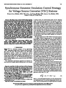
Fig. 3. Eigenvalue loci with a variation of (a) 𝐷1∗ (2−4 × 17 pu ~ 25 × 17 pu) or (b) 𝑋1∗ (2−4 × 0.7 pu ~ 25 × 0.7 pu).
0 0
Parameter 𝑆𝑏𝑎𝑠𝑒1 𝑆𝑏𝑎𝑠𝑒2 𝐸0 𝜔0 𝐸𝑖 = 𝑉𝑏𝑢𝑠
0 0
(9) 0 0 0 0
]
and 𝑩 is shown at the bottom of last page. Here, 𝐾𝑖 = (𝐸𝑖 𝑉𝑏𝑢𝑠 cos𝛿𝑖 )/𝑋𝑖 , and 𝑋𝑖 ≈ 𝑋𝑓 𝑖 + 𝑋𝑙𝑖𝑛𝑒 𝑖 . Analyses of transient active power control performance in the following parts of present section are based on this model, as it describes the transient performance of variables in 𝒚 after a given disturbance 𝒘. B. Oscillation Damping It is a known conclusion in the control theory that the poles of transfer function of 𝑌𝑗 (𝑠)/𝑊𝑘 (𝑠) are available in the eigenvalues of 𝑨, for any 𝑗, 𝑘 Therefore, the studies on eigenvalues of 𝑨 should give some clues to damping methods for oscillations in ∆𝑃𝑜𝑢𝑡 𝑖 . The loci of eigenvalues of 𝑨 with a variation of 𝐷1 or 𝑋1 are shown in Fig. 3. Nominal parameters are listed in Table I, in which 𝑀𝑖∗ = (𝐽𝑖 𝜔02 )/𝑆𝑏𝑎𝑠𝑒 𝑖 , 𝐷𝑖∗ = (𝐷𝑖 𝜔0 )/𝑆𝑏𝑎𝑠𝑒 𝑖 , and 𝑋𝑖∗ = (𝑋𝑖 𝑆𝑏𝑎𝑠𝑒 𝑖 )/𝐸02 . In the eigenvalue loci plots, radial dash lines indicate damping ratio 𝜁, and circle dash lines indicate natural frequency 𝜔𝑛 . As it is shown in Fig. 3, damping ratio of the complexconjugate eigenvalues increases if the damping factor 𝐷𝑖 and/or the output reactance impedance 𝑋𝑖 are increased. It should be pointed out that increasing 𝑋𝑖 causes a decrease in damped natural frequency 𝜔𝑑 , which is indicated by the distance between eigenvalue and the real axis. This may result in longer settling time compared to the method of increasing 𝐷𝑖 . However, the approach of increasing output reactance has other merits as follows. 1) The state-space model is obtained under the assumption that the output impedance of DGs is inductive. This assumption is less valid if 𝑋𝑖 is small, especially in a LV microgrid in which the line impedances are mainly resistive [42]. If this assumption is not valid, the active power and reactive power control cannot be decoupled correctly and the system may become more oscillatory and even unstable. 2) To share transient active power properly, output reactance of each DG should be designed equally in per unit
3)
TABLE I STATE-SPACE MODEL PARAMETERS Value Parameter 10 kVA 𝑀𝑖∗ 5 kVA 𝐷𝑖∗ 𝑘𝑝∗ 𝑖 200 V 376.99 rad/s 𝑋𝑖∗ 200 V
Value 8s 17 pu 20 pu 0.7 pu
value, as it is discussed in the next part of this section. Therefore, the problem of oscillation and that of transient active power sharing can be solved simultaneously by proper stator reactance design. Moreover, the influence of output reactance mismatch on transient active power sharing becomes smaller if output reactance of DGs is increased, owing to decreased relative errors.
C. Transient Active Power Sharing The response of output active power of DGs during a loading transition can be calculated from transfer functions ∆𝑃𝑜𝑢𝑡1 (𝑠)/∆𝑃𝑙𝑜𝑎𝑑 (𝑠) and ∆𝑃𝑜𝑢𝑡2 (𝑠)/∆𝑃𝑙𝑜𝑎𝑑 (𝑠), which are the elements 𝐺31 (𝑠) and 𝐺41 (𝑠) of the matrix 𝑮(𝑠) shown in (10), respectively. 𝑮(𝑠) = 𝑪(𝑠𝑰 − 𝑨)−1 𝑩 + 𝑫.
(10)
The loci of poles and zeros of ∆𝑃𝑜𝑢𝑡1 (𝑠)/∆𝑃𝑙𝑜𝑎𝑑 (𝑠) and ∆𝑃𝑜𝑢𝑡2 (𝑠)/∆𝑃𝑙𝑜𝑎𝑑 (𝑠) are shown in Fig. 4. It is shown that if the per unit value of 𝑋𝑖∗ , 𝑀𝑖∗ , and 𝐷𝑖∗ of each DG are set equally, all poles are cancelled by zeros. This cancellation implies a desirable step change of ∆𝑃𝑜𝑢𝑡1 and ∆𝑃𝑜𝑢𝑡2 directly to their respective steady-state values without any oscillation during a loading transition. Equal values of 𝑀𝑖∗ and 𝐷𝑖∗ are not difficult to realize since they are virtual parameters that can be easily changed in the VSG control program. As for 𝑋𝑖∗ , a control method to adjust stator reactance is presented in Section V. IV. IMPROVEMENT OF REACTIVE POWER SHARING Fig. 5 shows the principles of ω–P and V–Q droop controls in the “Governor Model” and “Q Droop” blocks shown in Fig. 1 for the case of 𝑆𝑏𝑎𝑠𝑒1 : 𝑆𝑏𝑎𝑠𝑒2 = 2: 1. As discussed in Section II, 𝑘𝑝∗ , 𝑘𝑞∗ , 𝑃0∗ and 𝑄0∗ are designed equally. Based on the predefined linear droop characteristic, the desired power sharing 𝑃𝑖𝑛1 : 𝑃𝑖𝑛2 = 2: 1 can be obtained because the governor input is 𝜔𝑚 , and 𝜔𝑚1 = 𝜔𝑚2 is guaranteed in steady state. Following the same principle, to share the reactive power according to the power rating ratio, an equal voltage reference is required. However, for the V–Q droop in basic VSG control shown in Fig. 1(c), the voltage reference is the inverter output
Fig. 4. Poles and zeros of (a) ∆𝑃𝑜𝑢𝑡1 (𝑠)/∆𝑃𝑙𝑜𝑎𝑑 (𝑠) and (b) ∆𝑃𝑜𝑢𝑡2 (𝑠)/∆𝑃𝑙𝑜𝑎𝑑 (𝑠). Left column: variation of 𝑋1∗ (2−4 × 0.7 pu ~ 25 × 0.7 pu); middle column: variation of 𝑀1∗ (1.3−4 × 8 s ~ 1.35 × 8 s); right column: variation of 𝐷1∗ (2−4 × 17 pu ~ 25 × 17 pu).
voltage, which may be a different value for each DG even in steady state due to the line voltage drop. As most of previous studies are based on Q–V droop, in which the output voltage 𝑉𝑜𝑢𝑡 𝑖 should be regulated based on measured reactive power 𝑄𝑜𝑢𝑡 𝑖 , the basic idea to address this problem is to equalize 𝑉𝑜𝑢𝑡 𝑖 by equalizing the output impedance [26], [27], or to compensate the line voltage drop [28]. Both methods need great effort in design process and complex computations in DG control law, whereas the resulted reactive power sharing is still influenced by active power sharing. As the voltage does not need to be controlled directly in a V–Q droop control scheme shown in Fig. 1(a), the reference voltage can be chosen other than inverter output voltage. If the common ac bus voltage 𝑉𝑏𝑢𝑠 is used instead of inverter output voltage 𝑉𝑜𝑢𝑡 𝑖 , equal reactive power reference value 𝑄𝑟𝑒𝑓1 = 𝑄𝑟𝑒𝑓2 can be guaranteed, as it is illustrated in Fig. 5. Therefore, accurate reactive power sharing 𝑄𝑜𝑢𝑡1 = 𝑄𝑜𝑢𝑡2 should be obtained through the using of reactive power PI controller. Moreover, unlike output voltage, bus voltage is not influenced by line voltage drop, which is determined by both active and reactive power. Therefore, reactive power sharing according to the bus voltage is independent from active power. In some previous researches [21], [39], [40], direct bus voltage measurement is suggested. However, in the field applications, it is difficult to measure 𝑉𝑏𝑢𝑠 directly, as DGs may
be installed far away from the common ac bus, and the utilization of communication is not preferred for reliability reason. Therefore, a bus voltage estimation method using local measurement is proposed in next section. V. PROPOSED ENHANCED VSG CONTROL SCHEME The proposed enhanced VSG control scheme is shown in Fig. 6. Compared to the basic VSG control, two major modifications are made, i.e., the stator reactance adjuster and the bus voltage estimator, as shown in Figs. 6(b) and 6(c), respectively. The function of stator reactance adjuster is to adjust the output reactance of the DG freely. It is operating as a virtual impedance controller. The virtual stator inductor is realized by multiplying output current by the virtual stator inductor in stationary frame. It will be more accuracy if inductor current through 𝐿𝑓 is used. However, this increases the number of current sensors, which is not necessary. As the current flowing into 𝐶𝑓 at fundamental frequency is less than few percent of the inductor current, using output current instead of inductor current does not affect the performance of the control scheme. Based on the given analyses in Section III and according to (11), tuning of virtual stator inductor 𝐿𝑙𝑠 is suggested to set total output reactance 𝑋𝑖∗ for both DGs in same large per unit value. This approach increases active power damping ratio and shares transient load without oscillation. The target value is proposed to be 0.7 pu because it is a typical value for the total direct-axis transient reactance 𝑋′𝑑 of a real SG. 𝑋𝑖∗ = 𝑆𝑏𝑎𝑠𝑒 𝑖 𝜔𝑚 𝑖 (𝐿𝑙𝑠 𝑖 + 𝐿𝑓 𝑖 + 𝐿𝑙𝑖𝑛𝑒 𝑖 )/𝐸02 = 0.7 pu.
Fig. 5. Principles of ω–P and V–Q droop control.
(11)
The 𝐿𝑓 𝑖 and 𝑍𝑙𝑖𝑛𝑒 𝑖 ( 𝑅𝑙𝑖𝑛𝑒 𝑖 + 𝑗𝐿𝑙𝑖𝑛𝑒 𝑖 ) are considered as known parameters in this paper. As the scale of microgrid is usually small, the line distance is easily to be measured or fed by the planner. Even if it is not the case, several online meas-
Fig. 7. Small-signal model of reactive power control loop. (a)
(b)
Fig. 8. Bode plot of reactive power control loop.
(c) Fig. 6. Block diagram of (a) the proposed enhanced VSG control, (b) the “Stator Reactance Adjuster” block and (c) the “Vbus Estimator” block.
urement or intelligent tuning methods for 𝑍𝑙𝑖𝑛𝑒 𝑖 are available in [42] and [43]. With the proposed design of stator reactance adjustment, oscillation in a VSG-control-based microgrid should be almost eliminated during a loading transition in islanded mode. Particularly, transition from grid-connected mode to islanded mode can also be considered as a loading transition; therefore, the oscillation during an islanding event should also be eliminated with the proposed control strategy, as it is proved by simulation results in next section. As for other disturbances in islanded mode, e.g. change of active power set value of DG(s), connection/disconnection of DG(s), etc., oscillation cannot be eliminated, but can still be damped by the increased total output reactance. The principle of bus voltage estimator in Fig. 6(c) is similar to that of stator reactance adjuster in Fig. 6(b). By calculating the line voltage drop in stationary frame using measured output current and line impedance data, the bus voltage can be estimated from the difference of output voltage and calculated line voltage drop. Since the RMS value of estimated bus voltage 𝑉̂𝑏𝑢𝑠 for each DG should be approximately equal, as it is discussed in last section, accurate reactive power sharing can be obtained by using estimated bus voltages as the input references of “Q Droop” instead of respective output voltages of
DGs. Although the principle of presented bus voltage estimator is not new, the idea of using this estimator to realize communication-less accurate reactive power sharing can be considered as a contribution in the present work. However, if there is an estimation error in 𝑉̂𝑏𝑢𝑠 , it will ∗ cause a reactive power sharing error. Supposing 𝑉̂𝑏𝑢𝑠1 = ∗ ∗ ∗ ∗ ∗ ̂ ̂ ̂ 𝑉𝑏𝑢𝑠 + ∆𝑉1 and 𝑉𝑏𝑢𝑠2 = 𝑉𝑏𝑢𝑠 + ∆𝑉2 , ∗ ∗ 𝑄𝑜𝑢𝑡1 − 𝑄𝑜𝑢𝑡2 = −𝑘𝑞∗ (∆𝑉̂1∗ − ∆𝑉̂2∗ ).
(12)
That is to say, the reactive power sharing error caused by estimation errors is determined by the V-Q droop gain 𝑘𝑞∗ . The design of 𝑘𝑞∗ is a well-known trade-off between voltage deviation and reactive power control accuracy. Considering the probable ripples in the measured RMS value of 𝑉̂𝑏𝑢𝑠 , 𝑘𝑞∗ is recommended to be 5 pu for the present example. It should be pointed out that the increased output reactance by adding the virtual stator inductor 𝐿𝑙𝑠 causes a decrease in the reactive control plant gain, as shown in Fig. 7. Therefore, to obtain a same bandwidth of 20 Hz for the reactive power control loop, the gain of PI controller should be increased to compensate the decreased plant gain, as illustrated in Fig. 8. The parameters used to plot Fig. 8 are related to DG1, which are shown in Fig. 9 and Table II. The 20Hz bandwidth is relatively low compared to control methods working on instantaneous value; however, it is fast enough to track the reactive power and regulate the output voltage as it is demonstrated in the simulation and experimental results.
VI. SIMULATION RESULTS
Fig. 9. Simulation circuit.
Parameter 𝑆𝑏𝑎𝑠𝑒1 𝑆𝑏𝑎𝑠𝑒2 𝐸0 = 𝑉𝑔𝑟𝑖𝑑 𝜔0 = 𝜔𝑔𝑟𝑖𝑑 𝑃0∗ 𝑖 𝑄0∗ 𝑖 ∗ 𝐾𝑝𝑞 𝑖 ∗ 𝐾𝑝𝑞 𝑖
Time t < 21 s 21 s ≤ t < 24 s 24 s ≤ t < 27 s 27 s ≤ t < 30 s
TABLE II SIMULATION PARAMETERS Common Parameters Value Parameter 10 kVA 𝑀𝑖∗ 5 kVA 𝐷𝑖∗ 𝑘𝑝∗ 𝑖 200 V 𝑘𝑞∗ 𝑖 376.99 rad/s 𝑇𝑓𝑞 𝑖 1 pu 0 pu Basic VSG control 𝑇𝑖𝑞 𝑖 0.0025 pu Enhanced VSG control 𝑇𝑖𝑞 𝑖 0.0125 pu
Value 8s 17 pu 20 pu 5 pu 7.96 × 10⁻³ s 1.25 × 10⁻⁴ s 1.25 × 10⁻⁴ s
TABLE III SIMULATION SEQUENCE ∗ ∗ 𝑃0_1 𝑃0_2 Grid Connected 1 pu 1 pu Disconnected – – – – – – – 0.6 pu
Load Load1 – Load1+2 –
Simulations are executed in PSCAD/EMTDC environment to verify the effectiveness of the proposed enhanced VSG control scheme. A microgrid shown in Fig. 9 is studied. As it is shown in Fig. 9, impedances of output filters and lines of each DG differ in per unit values. Other main parameters are listed in Table II, and the sequence of simulation is shown in Table III. Events of islanding from grid, loading transition, and intentional active power sharing change are simulated at 21 s, 24 s, and 27 s, respectively. The simulation results are shown in Fig. 10. As it is illustrated in Fig. 10(a), when the microgrid is islanded at 21 s, and when load 2 is connected at 24 s, oscillation can be observed in active power when the basic VSG control is applied for both DGs. This oscillation is almost eliminated by applying the proposed enhanced VSG control shown in Fig. 10(b). As the disturbance at 27 s is caused by change of active power set value of DG1, which is not a loading transition, active power oscillation cannot be eliminated in this case. However, the proposed enhanced VSG control increases the damping ratio; therefore, the overshoots in Fig. 10(b) are smaller than that in Fig. 10(a). Meanwhile, the oscillation periods become longer, because the damped natural frequencies are decreased as it is discussed in Section III-B. Note that the rate of change of frequency remains the same in all cases, which suggests that the proposed enhanced VSG control has no influence on the inertia support feature of VSG control. Moreover, in the case of the basic VSG control, reactive power is not shared properly in islanded mode, and is not controlled at set value in grid-connected mode, due to the voltage drop through the line impedance, as shown in Fig. 10(a). Besides, reactive power control is not independent from active power control, as a change of set value of active power at 27 s also causes a change of reactive power sharing. These problems are all solved in the enhanced VSG control, as it is
Fig. 10. Simulation results of active power and frequency in the left column and reactive power and voltage in the right column when both DGs are controlled by (a) the basic VSG control, (b) the proposed enhanced VSG control.
hanced VSG control, the voltage becomes slightly oscillatory, the reactive power oscillation converges within 0.1 s. VII. EXPERIMENTAL RESULTS
(a)
Experiments are executed in an islanding microgrid, of which the circuit is the same as that of simulation shown in Fig. 9, except that instead of dc sources, ac supply rectified by diode bridges is used to imitate the dc output of DGs, and the breaker BK3 is opened. The setup of experiment system is shown in Fig. 12 and experiment sequence is shown in Table IV. Control Parameters are the same as those listed in Table II, and the experimental results are shown in Fig. 13.
Time t < 0.5 s 0.5 s ≤ t < 3 s 3s≤t