Nov 1, 1989 - Such identification does not imply recommendation or ...... tolerance on the diameter of a hole. .... is any continuous collection of straight line segments and arcs of circles joined .... Two methods of constructing arc-splines have been ... the drawing into pieces, each of which is approximately an arc of a circle.
NISTIR 89-4201
November 1, 1989
ENHANCEMENTS TO THE VWS2 DATA PREPARATION SOFTWARE
By: Thomas R. Kramer
ENHANCEMENTS TO THE VWS2 DATA PREPARATION SOFTWARE
Dr. Thomas R. Kramer Guest Researcher, National Institute of Standards and Technology, & Research Associate, Catholic University
November 1, 1989
Funding for the research reported in this paper was provided to Catholic University under Grant No. 70NANB9H0923 and Grant No. 70NANB7H0716 from the National Institute of Standards and Technology. Certain commercial equipment and software are identified in this paper in order to adequately specify the experimental facility. Such identification does not imply recommendation or endorsement by the National Institute of Standards and Technology, nor does it imply that the equipment or software identified are necessarily the best available for the purpose.
VWS2 Enhancements CONTENTS Page I. INTRODUCTION ....................................................................................................................1 1. CONTENTS.........................................................................................................................1 2. AUDIENCE .........................................................................................................................2 3. BRIEF DESCRIPTION OF THE VWS2 SYSTEM............................................................2 4. DEVELOPMENT HISTORY..............................................................................................3 5. RELATED READING ........................................................................................................3 6. MISCELLANEOUS SYSTEM CHANGES .......................................................................4 II. CONTOUR OUTLINE METHODS.......................................................................................5 1. INTRODUCTION ...............................................................................................................5 2. MAKING CONTOUR OUTLINES BY LOCATING AND ROUNDING CORNERS.....6 3. MAKING CONTOUR OUTLINES BY LOCATING CONTROL POINTS .....................7 4. PICKING POINTS WITH A MOUSE................................................................................7 5. SOFTWARE ........................................................................................................................8 III. TEXT SYSTEM ..................................................................................................................10 1. INTRODUCTION .............................................................................................................10 1.1. Characteristics of Old Text System ............................................................................10 1.2. Need for New System .................................................................................................10 1.3. Related Enhancement .................................................................................................10 1.4. Characteristics of New Text System...........................................................................10 1.5. Invisible Changes........................................................................................................11 1.6. Drawback to New System: Slowness .........................................................................11 2. TEXT DATABASE ...........................................................................................................12 2.1. Introduction.................................................................................................................12 2.2. Text Database File .......................................................................................................12 2.2.1. Introduction...........................................................................................................12 2.2.2. Font Representation ..............................................................................................12 2.2.3. ASCII Table ..........................................................................................................12 2.2.4. Character Representation ......................................................................................12 2.3. Text Database in the LISP Environment .....................................................................14 2.4. Trimming a Character ..................................................................................................15
-i-
VWS2 Enhancements 3. NEW TEXT PARAMETERS............................................................................................16 3.1. Introduction.................................................................................................................16 3.2. Bottom_type................................................................................................................17 3.3. Rotation.......................................................................................................................18 3.4. Text Path .....................................................................................................................18 3.5. Spacing........................................................................................................................19 3.6. How the New Parameters are Used ............................................................................19 3.6.1. Introduction...........................................................................................................19 3.6.2. If Text Located by Lower Left Corner .................................................................19 3.6.3. If Text Located by Text Path ................................................................................20 4. ENHANCING TEXT ........................................................................................................20 4.1. Introduction.................................................................................................................20 4.2. Enhance_text Function ...............................................................................................21 4.3. Enhance_text3 Function .............................................................................................21 4.4. Enhance_text1 Function .............................................................................................21 4.5. Enhance_char Function...............................................................................................21 5. ADDING A NEW CHARACTER .....................................................................................22 6. SOFTWARE ......................................................................................................................22 IV. TOLERANCE INFORMATION ........................................................................................24 1. INTRODUCTION .............................................................................................................24 2. HOLE CENTER TOLERANCE .......................................................................................24 3. HOLE DIAMETER TOLERANCE ..................................................................................25 4. DISCUSSION ....................................................................................................................26 4.1. Why "med" and "hi"?..................................................................................................26 4.2. The Future of Tolerance Information .........................................................................26 V. BOUNDARY REPRESENTATION PARSER....................................................................27 1. INTRODUCTION .............................................................................................................27 2. SOFTWARE ......................................................................................................................28 VI. DESIGN PROTOCOL AND PART DESIGN EDITOR ....................................................30 1. DESIGN PROTOCOL.......................................................................................................30 2. PART DESIGN EDITOR ..................................................................................................31 2.1. Introduction.................................................................................................................31 2.2. Revised Commands ....................................................................................................31 2.2.1. Change Feature ....................................................................................................31 2.2.2. New Design..........................................................................................................31 2.3. New Commands..........................................................................................................32
- ii -
VWS2 Enhancements VII. 1. 2. 3. 4.
SCULPTED CONTOUR GROOVES ...............................................................................33 INTRODUCTION .............................................................................................................33 SCULPTING ALGORITHM ............................................................................................36 ALTERNATE SCULPTING ALGORITHMS..................................................................37 SOFTWARE ......................................................................................................................37
VIII. FILES AND LISP ENVIRONMENTS ............................................................................38 1. LISP ENVIRONMENTS...................................................................................................38 1.1. Introduction.................................................................................................................38 1.2. Running the LISP Environments ................................................................................38 1.2.1. Introduction...........................................................................................................38 1.2.2. Control Environment ............................................................................................39 1.2.3. Data Preparation Environment..............................................................................39 1.3. Building Environments ...............................................................................................39 2. FILE STRUCTURE...........................................................................................................40 2.1. Introduction..................................................................................................................40 2.2. VWS2 Directory ..........................................................................................................40 2.2.1. Introduction...........................................................................................................40 2.2.2. Files.......................................................................................................................40 2.2.3. Subdirectories .......................................................................................................40 2.3. VWS3 Directory ..........................................................................................................42 REFERENCES ...........................................................................................................................44 APPENDIX A - PART DESIGN EDITOR TUTORIAL
- iii -
VWS2 Enhancements LIST OF FIGURES Page Figure 1. A Contour Outline .........................................................................................................5 Figure 2. Text Paths for Letters A, o, and G...............................................................................13 Figure 3. Tilting and Trimming the Letter G..............................................................................17 Figure 4. Text Path Data .............................................................................................................18 Figure 5. Various Text Location Methods..................................................................................19 Figure 6. A Part With Sculpted Contour Grooves ......................................................................33 Figure 7. Sculpted Contour Grooves ..........................................................................................35
- iv -
VWS2 Enhancements LIST OF TABLES Page Table 1. Table 2. Table 3. Table 4. Table 5. Table 6.
New Contour Outline Functions....................................................................................9 New and Revised Text System Functions ..................................................................23 VWS2 Brep Parser Functions ......................................................................................29 Summary of Design Protocol Changes........................................................................30 VWS2 Subdirectories ..................................................................................................41 VWS3 Subdirectories ..................................................................................................43
-v-
ENHANCEMENTS TO THE VWS2 DATA PREPARATION SOFTWARE
I.
INTRODUCTION 1. CONTENTS
This paper discusses enhancements made between September 1987 and December 1988 to the data preparation software for the Vertical Workstation (VWS) of the Automated Manufacturing Research Facility (AMRF) at the National Institute of Standards and Technology (NIST). NIST was formerly the National Bureau of Standards. Chapter II discusses the new methods which were developed for creating contour outlines. The new methods allow graphical input for describing a contour outline, provide several means of rounding the corners of a contour outline, and provide two methods for automatic construction of a contour outline from a set of control points. In the spring of 1988 the text system was totally rebuilt. Chapter III describes the new text system. The new system provides all the capabilities of the old system (choice of fonts, ability to make new fonts, variable height, etc.) plus: variable spacing, variable rotation of individual characters, ability to locate text along a contour outline path, verification character by character rather than by string, choice of round-bottomed or vee-bottomed style (using ball-nosed end mill or engraver), lower case letters, and easier creation of new characters. In addition, invisible to the user, the new system does on-line transformation of characters, rather than using stored transformed characters. A new, much simpler method of representing the shape of characters is used in the new system. Chapter IV describes how tolerance information has been introduced into the design protocol used in the VWS. It also discusses a new algorithm for cutting flat-bottomed holes, which uses the probe on the machining center for in-process metrology. The new algorithm is used to achieve higher tolerance on the diameter of a hole. Chapter V discusses a parser that was added to the system. The parser reads a PDES/STEP boundary representation file that gives the shape of a part and writes an equivalent features file in the format used by the Vertical Workstation. By having the VWS control system call the data preparation software (with the parser) automatically, parts which the parser can handle (a subset of the family of parts that can be expressed in the VWS design protocol) may be made directly from PDES/STEP files without human intervention, once the command to make the part has been given. Chapter VI describes changes which have been made to the Part Design Editor. Two general types of changes were made: those necessary to have it work correctly to implement the items presented in other chapters, and those which were implemented solely to improve the Editor itself. Chapter VII describes an algorithm which has been added to the system for the smooth threedimensional sculpting of contour_grooves. Chapter VIII describes the file structure of the enhancements and how a VWS2 LISP environment which includes the enhancements may be built and run. -1-
VWS2 Enhancments 2. AUDIENCE The paper is intended to be useful to people interested in concepts and technical details of the VWS, particularly researchers at Manufacturing Technology Centers using the VWS software and AMRF personnel who are running the VWS or maintaining or improving the software for the VWS. The paper is intended to be useful also to other researchers in automated manufacturing. Knowledge of the computer language LISP and of machining is useful but not essential to reading this paper. 3. BRIEF DESCRIPTION OF THE VWS2 SYSTEM The VWS is a computer-integrated automated machining workstation. It includes a control system, a computer-aided design system, an automatic process planning system, and an automatic NC-code generator. The principal machinery is a machining center (Monarch VMC-75 with a GE2000 controller) and a robot (Unimate 4070 with a Val II controller) to tend the machining center. There is quite a bit of ancillary hardware. The system is controlled from a microcomputer (Sun 3/160 with 8 Mb memory, BW monitor). Running in stand-alone mode, it is possible to design and machine a simple metal part within an hour. The VWS may also be run as an integrated part of the AMRF. The software for the VWS is written in the Franz LISP dialect of the computer language LISP. In this paper this software is called the VWS2 system. Seven principal modules comprise the VWS2 system: the Production Management Operating System (the control system), the State Table Editor, the Equipment Program Generator, the Part Design Editor, the Process Planner, the Data Execution module, and the PDES/STEP boundary representation parser. In addition to the principal modules, there are three sets of software that serve several modules and may be thought of as subsystems: graphics, verification, and data handling. The Part Design Editor, Process Planning and Data Execution modules, as well as other system capabilities, may be accessed by the user through a small user interface called vws_cadm. Vws_cadm asks the user questions about what the user wants to do and then activates the appropriate module or other capability accordingly. To produce a part from scratch, the user creates a design. The Process Planner is then called to write a plan for how to machine a part of that design. Next, NC-code is generated automatically from the design and the plan by the Data Execution module. Finally the user tells the control system to make the part. The control system coordinates the activities of the workstation equipment so that the part blank is loaded onto the machining center, the NC-code is sent to the machining center and executed (making the part), and the finished part is unloaded. Usable designs may be created either at the Sun workstation using the VWS2 Part Design Editor, which generates a feature-based design directly, or by creating a boundary representation in PDES/ STEP file format and using the Parser to extract a feature-based design. In the AMRF, designs in PDES/STEP format may be created by doing the initial design on a Computervision CADDS station, using "solid-design" (a constructive solid geometry package), automatically extracting a -2-
VWS2 Enhancments boundary representation in AMRF standard format, and automatically converting that to PDES/ STEP format. 4. DEVELOPMENT HISTORY The VWS2 software was developed in the environment of the AMRF. In 1985 the predecessor of the VWS2 system was demonstrated. It used a document which was a combined design and process plan as its chief item of data. Development of the VWS2 system, which separates design from process planning, began in the fall of 1985. A working version was demonstrated in June 1986. Development continued at a rapid pace through September 1987. The system was documented in detail as it existed in September 1987. Enhancements to the system were built from time to time until the end of 1988. Since then, there has been almost no further development. The overall architecture of the system was suggested by Mr. Charles McLean. The Production Management Operating System and the State Table Editor were built largely by Dr. Jau-Shi Jun with the assistance of Mr. McLean. The Equipment Program Generator was built by Mr. Ibrahim Nakpalohpo with assistance from Dr. Jun. Dr. Jun built the initial version of the Part Design Editor (with graphics routines written by the author). The remainder of the system was built by the author with the assistance of Mr. W. Timothy Strayer (summer 1987) and Ms. Rebecca E. Weaver (summer 1988). The VWS2 software would not have been developed if there had not been a VWS to which to apply it. The VWS hardware (and the software for its low-level control) was put together by a group including Mr. Frederick Rudder, and Mr. Denver Lovett and originally headed by Dr. Edward Magrab. In the past two years, Mr. Simon Frechette has also worked on the hardware side of the VWS. 5. RELATED READING This paper is one of about a dozen papers prepared as part of the AMRF documentation to describe all aspects of the VWS. The others are [JUN], [KRA1], [KRA3], [KRA4], [KRA5], [KRA6], [K&J2], [K&S2], [KR&W], [LOVE], [NA&J], and [RUDD]. Other papers, prepared for professional meetings and journals, also describe the VWS [KRA2], [KRA7], [KRA8], [K&J1], and [K&S1]. This paper is essentially an update of the collection of AMRF documentation papers given above. In some cases it will be necessary to refer to those papers to get a clear picture. The best overview of the VWS2 system is given in Software for an Automated Machining Workstation [K&J1], although some details given in that paper are now out of date. 6. MISCELLANEOUS SYSTEM CHANGES Two changes in the system have been made which do not fall in any other chapter of this paper. For completeness, they are given briefly here. -3-
VWS2 Enhancments Whenever the feature enhancement system is asked to enhance a feature, it now prints a message which says whether it was successful or not. This change was made to keep the user better informed of what the system is doing, particularly during operation of the Process Planning module and early stages of the Data Execution module. The change also causes the Design Editor to print more messages than it did previously. The process planner now prints a message each time it attempts to find operations for making another feature. This change was made to keep the user better informed of what the Process Planning module is doing.
-4-
VWS2 Enhancments II.
CONTOUR OUTLINE METHODS 1. INTRODUCTION
The VWS2 design protocol includes three feature types (contour_pocket, side_contour and contour_groove) that make use of a planar curve called a contour outline. Contour outlines are discussed in detail on pages 63 through 69 of [K&J2], where they are called "defining lines" for contour features. Contour outlines are the sole subject of [KRA8]. For full understanding of this chapter, it is suggested that those references be read before continuing here. A contour outline is any continuous collection of straight line segments and arcs of circles joined end to end. A contour outline may be either open or closed. If a contour outline is to be used to outline a portion of a plane (as it is in contour_pockets and side_contours), it must be closed and must not intersect itself. Contour outlines were defined using straight line segments and circular arcs because those are the path shapes that machining centers can make with single commands.
Figure 1. A Contour Outline 2
3
1
7 6 4
Corners 1 (x 1.3 2 (x 2.0 3 (x 2.6 4 (x 2.6 5 (x 3.5 6 (x 3.68 7 (x 5.0
y 2) y 2.5 radius 0) y 2.5 radius 0.6) y 0.0 radius 0.6) y 0.0 radius 0.6) y 0.24 radius 0.0) y 0.8)
5
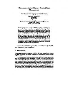
A contour outline is represented in the VWS2 design protocol by a "corners" data structure, which specifies a frame of straight line segments plus the radii of any arcs in the outline. An example is shown in Figure 1. The contour outline, which is shown with a black line, is open and is made up of three straight line segments and two circular arcs. The frame, which is shown with a wide grey line, includes seven corners, three of which are rounded. The positions of the corners are given by x and y coordinates. Each arc that fits into a corner is understood to be tangent to the sides of the frame that meet at the corner. The corners data for the example is given in the figure. Corners which are rounded have a positive arc radius specified, corners which are not rounded and are not ends of an open contour outline have a zero radius specified, and ends of open contour outlines have no radius (or a radius value of nil). -5-
VWS2 Enhancments The definition of a contour outline has not been changed in the VWS2 enhancements, but several improvements have been implemented. There are now two distinct approaches to constructing a contour outline: either by locating corners or by locating control points. These changes have been completely integrated with the VWS2 system. Because the Process Planner and Data Execution Modules and the Verification subsystem work with the enhanced corners description when dealing with contour features, no changes in those parts of the system were required for integration. 2. MAKING CONTOUR OUTLINES BY LOCATING AND ROUNDING CORNERS A contour outline may be defined by locating the corners of a frame and then specifying how the corners are to be rounded. Corners may be located either by typing coordinates at the keyboard or by using the mouse, according to whether the mouse is off or on, as described below. Regardless of which device is used, the user has five choices while corners are being located: 1. Add a corner at the end 2. Insert a corner before an existing corner 3. Change a corner 4. Delete a corner 5. Stop locating corners After the user is done locating corners, there is a choice of five methods of rounding the corners. None of these uses the mouse, regardless of whether it is off or on. 1. Specify a unique radius at each corner. 2. Use the same radius for all corners. 3. Let the system calculate radii automatically and specify a percentage to be applied to all the system-generated radii. 4. Specify a unique radius at some corners, and let all other corners have equal radii, the value of which is specified by the user. 5. Specify a unique radius at some corners, and let the system calculate radii automatically for the other corners (again specifying a percentage to be applied to all system-generated radii). The default value of the radius of a corner is 0. The system distinguishes between a zero written without a decimal point (0) and a zero written with one (0.0) for implementing options 4 and 5 above. If the radius is given as 0.0, that means the radius should be zero. If the radius is given as 0, that means the corner should be rounded automatically by the method for "other corners". This distinction gives the user an easy method of specifying sharp (zero radius) corners. In [KRA8] the logical value of "auto" is used for the radius of a corner which is to be rounded automatically. This logical distinction is implemented by the difference between 0 and 0.0.
-6-
VWS2 Enhancments While the user is specifying unique radii, there are three choices: 1. Select the number of the corner for which a radius is to be given, and then assign a radius, which may be a positive number, join_ahead, or join_back. The same corner may be selected several times during the process if the user has a change of mind. 2. Stop assigning radii. 3. Undo the assignment of a radius to any corner. A list of the original radius at each corner plus any assignment made by the user is kept during the process to allow undoing. If the undo option is chosen, the user must then specify which corner should be undone. If the user has changed the radius of a corner several times, the undoer will roll back through each assigned value in reverse order. The system performs many checks during the process, such as "Does that corner exist?" or "Is there anything to undo?". 3. MAKING CONTOUR OUTLINES BY LOCATING CONTROL POINTS The user may locate a number of control points near which a contour outline should pass and then let the system extract a corners data structure for the outline automatically. Contour outlines constructed this way are called "arc-splines". Two methods of constructing arc-splines have been implemented: expert and easy. A full description of the both methods is given in [KRA8]. Both methods require that the mouse be used to locate control points. Allowing an option for using the keyboard to locate control points could have been implemented in principle (in fact, experience has proved it would be very useful for making fine adjustments of control points), but this has not been done. The expert method is useful only for copying an existing line drawing, such as a signature. It is called "expert" since it requires some expertise on the part of the user, who must start by dividing the drawing into pieces, each of which is approximately an arc of a circle. The easy method is useful either for copying an existing line drawing or for drawing from scratch on the computer screen. 4. PICKING POINTS WITH A MOUSE Point picking with a mouse has been implemented in the Design Editor for locating corners or control points. The mouse is activated and deactivated by new user commands: mon - to activate the mouse moff - to deactivate the mouse. When the user gives a "mon" or a "moff" command, an internal flag is set in the Design Editor, and the user is informed that the mouse is "on" or "off". Nothing else happens at that time. Whenever the user elects to make any feature requiring a contour outline, however, the keyboard must be used to define the outline if the mouse is "off" and the mouse must be used if it is "on". When the Design Editor is started up, the mouse is "off". The mouse is used in the usual way by pointing at a spot on the screen and clicking a button or two.
-7-
VWS2 Enhancments When the mouse is being used to locate corners, the 5 choices listed earlier are indicated as follows: 1. Add a corner at the end (one click of the left or middle button). 2. Insert a corner before an existing corner (quickly click the left button then the middle button). The user must use the keyboard to identify the existing corner. 3. Change a corner (two quick clicks of the left button). The user must use the keyboard to identify which corner is to be moved. 4. Delete a corner (two quick clicks of the middle button). The user must use the keyboard to identify which corner is to be deleted. 5. Stop locating corners (one click of the right button). When the mouse is used to locate control points for either arc-spline method, the user has six choices: 1. Mark a control point at the end of the list which should become a sharp corner (one click of the left button). 2. Mark a control point at the end of the list that should lie on a smooth portion of the final contour outline (one click of the middle button). 3. Move a control point and, if there is a choice, specify whether it is to be sharp or smooth (two quick clicks of the left button). The user must use the keyboard to identify which point is to be moved and whether it is sharp or smooth. 4. Delete a control point (two quick clicks of the middle button). The user must use the keyboard to identify which point is to be deleted. 5. Insert a control point before an existing control point (quickly click the left button then the middle button). The user must use the keyboard to identify the existing control point and specify whether the new point is sharp or smooth. 6. Stop locating control points (one click of the right button). 5. SOFTWARE All of the new software for contour outlines is in the design3 and geom3 directories, although minor changes had to be made to existing functions in other directories to integrate the methods fully. The names of the new functions are given in Table 1.
-8-
VWS2 Enhancments
Table 1. New Contour Outline Functions design3 directory
geom3 directory
center_from_3pts cornify_expert cornify_ez gen_corners get_contour get_contour_parms get_corner_radius get_fast_button get_keyboard_corners get_mouse_corners get_mouse_location get_mouse_points inflectp perp_at_pt2 specify_radii
check_corners enhance_aux_global enhance_cont_global mid_direction place_midpoint
-9-
VWS2 Enhancments III. TEXT SYSTEM 1. INTRODUCTION 1.1. Characteristics of Old Text System The old text system is described in detail in [K&J2] pages 59 to 62 and 77 to 84. The old system had the capability to make upper case alphabetic characters plus the ten digits, a period, a space and a dash. All characters were available in five different fonts: plain, round, broad, italic, and angular. Letters could be entered in lower case, but they would be converted to upper case for machining. Text was located by specifying values for the x and y coordinates of the lower left corner of the text string, and the text string extended from the left to right on the part, parallel to the x-axis. For verification purposes, the physical extent of the text in the xy-plane was represented by a parallelogram with rounded corners which just fit around the text. The only bottom style for text was "round", so that text was always machined with a ball-nosed end mill. An easy-to-use (for LISP programmers) function was written to make it simple to create new fonts, but was not made available from the user interface. The old text system was a stroke-based system, in which data for each character represented instructions for generating the strokes required in drawing or machining the character. In a computer graphics language like Postscript, both raster fonts and stroke-based fonts are possible. For machining, only stroke-based fonts are feasible. 1.2. Need for New System In the spring of 1988, the Department of Commerce requested that a plaque be made for the 75 Anniversary of the Department. The draft design for the plaque included text arranged in a circle, as well as small lower case letters. It was necessary to revise the text system to provide for making this plaque. The revisions that were done went somewhat beyond what was essential. 1.3. Related Enhancement The capability to copy handwritten text was also added to the system during the year, but this is accomplished by contour outline methods described in the previous chapter. 1.4. Characteristics of New Text System The new system provides all the capabilities of the old system plus: variable spacing, variable rotation of individual characters, ability to locate text along a contour outline path, choice of roundbottomed or vee-bottomed style, lower case letters, and easier creation of new characters. The new system is stroke-based, like the old one. Three characters were added: apostrophe, comma, and star. The star is represented by an asterisk in the text string in the design. It is machined as a five-pointed star. 1.5. Invisible Changes
- 10 -
VWS2 Enhancments A number of other changes, invisible to the user, were made. The data base for characters and fonts was revised. Formerly, each character was represented by a set of points and a set of instructions for joining the points together. The new system represents each character as one or more contour outlines. This allows the text system to take advantage of contour outline routines developed for other purposes. The old system stored a transformed version of each character for each font. The new system does on-line transformation of characters, so that storage requirements are smaller. In the new system, verification is done on each contour outline of each character, so that exact, rather than approximate verification is done. In order to provide for the rotation of individual characters, the transformations used to convert the "plain" font to another font were changed. The old transformations required that any straight portion of a character that was attached to an arc of the character be either vertical or horizontal, in the plain font. The old transformations also required that any arc in a character must be a quarter circle in one of four orientations. Specifically, the tangents to the end points of any arc had to be either vertical or horizontal. The new transformations have no such restrictions. In the old system, the user could make a new font by a call to the "new_font" function. Whenever new_font was run, it transformed all characters and stored them. If the user asked new_font to attempt an impossible transformation by specifying an out-of-bounds parameter, the font maker would change the parameter value to be in bounds. Once the font was made, all characters could be used. In the new system, a new font is made by adding a line to the "char_desc" file. No characters are transformed when the font is defined, so the user does not get an early warning if a character is not transformable. Because of the limits of certain transformations, most lower case letters which include any arcs cannot be used in the "round" and "angular" fonts. If the user tries to design a part using the Design Editor which has a text feature that includes characters that are not transformable into the desired font, the user is informed by the Editor which characters are not transformable. 1.6. Drawback to New System: Slowness Because of the improved verification, the time taken for verification of a text feature when it has a reference feature has increased substantially, perhaps by a factor of eight. When using the design editor, a typical user will find the wait for verification of text features with reference features irritating, but not intolerable. A long text string will also take quite a while to enhance. Enhancement time is appreciably less than the time required for verification just described. Time required for drawing and NC-code generation has not changed appreciably.
- 11 -
VWS2 Enhancments 2. TEXT DATABASE 2.1. Introduction The new text database, like the old one, has two formats: one for the file in which the database is stored, and one for use in the active LISP environment. The file format is designed for easy use by a human who understands the format, while the data in the active LISP environment is formatted for easy and efficient handling by the VWS2 system. 2.2. Text Database File 2.2.1. Introduction The text database file "char_desc" sets up the property list of "fonts" when it is loaded into the LISP environment. Then the list is automatically reformatted. 2.2.2. Font Representation The parameters required to transform a character into a new font (curve, hw_ratio, mirror, radius, roundness, spacing, and tilt) are stored for each of the five fonts. Unused properties may be omitted. The data for the plain font, for example (which does not use curve or mirror), are: (plain radius 0.1666666666666667 spacing 0.3333 tilt 0.0 roundness 0.6667 hw_ratio 1.5) 2.2.3. ASCII Table An ASCII table gives the name of the character to be machined along with the ASCII value for the representation of the character in a string. For example, the name of ASCII character number 65 is "A", the name of ASCII character number 32 is "space", and the name of ASCII character number 42 is "star". 2.2.4. Character Representation The only other portion of the file is called "characters". For each character named in the ASCII table, a list is given which represents (in a shorthand notation) the contour outlines which comprise the character. The letters A, G and o will be used as examples to explain the notation. A picture of letter "A" is shown in Figure 2a. The data in the file for the letter "A" is: A (((0 0 n) (3 6 0) (6 0 n)) ((1 2 n) (5 2 n)))
- 12 -
VWS2 Enhancments
Figure 2. Text Paths for Letters A, o, and G
a
b Text Paths A (((0 0 n) (3 6 0) (6 0 n)) ((1 2 n) (5 2 n))) o (((0 0 r) (0 3 r) (3 3 r) (3 0 r))) G (((2.5 2 n) (4.5 2 0) (4.5 0 r) (0 0 r) (0 6 r) (4.5 6 r) (4.5 3 t))) The frame of the path is shown with a thin black line.
c
The character is shown with a thick grey line.
Notice that the data for "A" consists of two sublists. The first sublist describes the sides of the "A" and the second sublist describes the crossbar of the "A". There are two sublists because two separate passes with a cutting tool are required to make the character. The first pass cuts from the bottom left to the top to the bottom right, and the second pass cuts the crossbar. The system can handle any number of sublists, but most characters require only one pass, and no character requires more than three passes. Thus, there are one to three sublists. Each sublist for a character consists itself of sublists, each of which has three entries and represents one corner in a contour outline. The first entry represents the x-value of the corner, and the second - 13 -
VWS2 Enhancments the y-value. The range of values for x is 0 to 6, and for y is -2 to 6. Negative values of y are used for letters with "descenders", such as lower case y or g. The dimensions of the grid were chosen purely for convenience in designing characters. With these dimensions, the radius of arcs in the plain font is 1 unit. Also, with this size grid, most of the x and y values are integers, which is convenient. All upper case letters and all digits are 6 units high. The third entry in the sublist that represents a corner is one of the following four choices: n -- An n means that this corner is the endpoint of an open contour outline. r -- An r means that there is an arc in this corner, and the corner is not an endpoint. All arcs for characters of a given height in a given font have the same radius. 0 -- A 0 means that there is no arc in this corner, and the corner is not an endpoint. t -- A t means that this corner is at the end of an open contour outline and is the endpoint of a straight line segment which should be trimmed back (after the fonting transformations have been applied) to the point where the segment joins an arc at the preceding corner. This oddity is explained later in this chapter. Thus the very first sublist for the letter "A" (0 0 n), means that the first corner of the outline is where x=0 and y=0, and the outline is an open outline. The data for "o", which is shown in Figure 2b, are: o (((0 0 r) (0 3 r) (3 3 r) (3 0 r))) Since the first and last corners of "o" do not have "n" or "t" as the last entry, the contour outline is closed. Unlike "A", which has no rounded corners, all four corners of "o" are rounded. The character "G", shown in Figure 2c, has the data: G (((2.5 2 n) (4.5 2 0) (4.5 0 r) (0 0 r) (0 6 r) (4.5 6 r) (4.5 3 t))) This is an open contour outline (since the last entries of the first and last sublists are "n" or "t") in which most corners are rounded, but one (the second one) is not. Trimming is required at the last corner. 2.3. Text Database in the LISP Environment In order to be usable with contour outline routines, the text database is put into property list format when it is brought into the LISP environment (i.e. active memory). The font information and the ASCII table are already in property list format, so they do not need to be changed, but the character information is changed extensively. The representation of "A" becomes: - 14 -
VWS2 Enhancments A (A max 1.0 grooves ( (A 1 (1 x 0.0 y 0.0) 2 (2 x 0.5 y 1.0 radius 0) 3 (3 x 1.0 y 0.0)) (A 1 (1 x 0.1666666666666667 y 0.3333333333333333) 2 (2 x 0.8333333333333334 y 0.3333333333333333)))) The first change to notice is that all x and y values are one-sixth what they are in the file, and that "x", "y", and "radius" are written out. Reducing x and y values makes the height of upper case letters 1 unit, which is more convenient as a starting point for transformations. If a corner had "n" in the file, no radius at all is listed in the LISP environment. A new property, "max" has been added. This is simply the maximum value of x reached anywhere on the character. It is used by functions in the text system which need to measure the length of text strings. The value of the "grooves" property is simply a reformatted version of the data in the file for the character. The corners of each contour outline making up the character are numbered, starting with 1. The name of the character ("A" above) is inserted in several locations for formatting and information carrying purposes. The representation of "G" becomes: G (G max 0.75 grooves ( (G 1 (1 x 0.4166666666666667 y 0.3333333333333333) 2 (2 x 0.75 y 0.3333333333333333 radius 0) 3 (3 x 0.75 y 0.0 radius r) 4 (4 x 0.0 y 0.0 radius r) 5 (5 x 0.0 y 1.0 radius r) 6 (6 x 0.75 y 1.0 radius r) 7 (7 x 0.75 y 0.5 trim t)))) 2.4. Trimming a Character Trimming was introduced to solve a problem with transforming arcs when a font is tilted, which occurs when an open contour outline ends in an arc. Understanding the problem requires understanding how tilting is done, which requires knowing how a contour outline is constructed. This is described in detail in [K&J2] pages 63 through 66. The important facts are as follows: The straight lines connecting successive corners of a contour outline make a "frame" for the outline. The frames of the letters are shown with a thin black line in Figure 2 and Figure 3. To tilt - 15 -
VWS2 Enhancments a character, first the frame is tilted, then any corners requiring rounding are rounded, and finally, any dangling line requiring trimming is trimmed. Rounding is accomplished by inserting an arc of the radius given in the font specification into the corner, so that the arc is tangent to the sides of the frame. Tilting a frame is accomplished by moving each corner of the frame horizontally (in the x direction) by an amount equal to the tilt factor times the y-value of the point. In equation form, this means:
ynew = yold xnew = xold + T*yold Figure 3 shows the letter "G" again. On the left, the G is untilted. On the right, the G has been tilted using a tilt factor of 0.25 Observe that the end of the arc at the upper right of the G is lower than the corresponding end of the untilted G. The last straight segment of the frame for the G is used to locate that arc, but then the remaining straight portion of the segment is trimmed away. 3. NEW TEXT PARAMETERS 3.1. Introduction In the old text system, the following parameters were required to specify a text feature: feature_type -- must be "text" text -- a string giving the characters to use lower_l_x -- the x-coordinate of the lower left corner of the text lower_l_y -- the y-coordinate of the lower left corner of the text height -- the scale factor to be applied to the characters as defined in the text database (in the database the height of all upper case letters is 1) depth -- depth of cut line_width -- width of cut Two additional parameters were optional: font -- the name of an existing font (normally one of the five fonts listed above). If no value for font is given, the plain font is used. reference_feature -- If the text is to be made at the bottom of some other feature, this is the feature number of that feature.
- 16 -
VWS2 Enhancments
Figure 3. Tilting and Trimming the Letter G
trim away
trim away
On the left the character is untilted. On the right it is tilted with a tilt factor of 0.25. untilted (((2.5 2 n) (4.5 2 0) (4.5 0 r) (0 0 r) (0.0 6 r) (4.5 6 r) (4.50 3 t))) tilted
(((3.0 2 n) (5.0 2 0) (4.5 0 r) (0 0 r) (1.5 6 r) (6.0 6 r) (5.25 3 t)))
The frame of the path is shown with a thin black line. The character is shown with a thick grey line. Observe that the end of the arc at the upper right is lower in the tilted character.
Four new parameters were added to allow more ways of locating and machining text: bottom_type, rotation, text path, and spacing. Some of these parameters interact with other parameters, as discussed below. The VWS2 Design Editor has been changed to take these parameter interactions into account automatically, and prevent inconsistent values of the parameters. 3.2. Bottom_type Bottom_type is a required parameter. The value of bottom_type may be either "round" or "vee". If the bottom_type is round, the depth and line_width of the text determine the radius of the tool which cuts the text. If the bottom_type is "vee", the angle of the vee is assumed to be 90 degrees, so that line_width must be twice depth. 3.3. Rotation
- 17 -
VWS2 Enhancments Rotation is an optional parameter. If it is used, its value must be a number. This is the number of radians which each character should be rotated counterclockwise after it has been placed either by locating the lower left corner of the text or by specifying a text path. If text path is specified, the total rotation of any character will be the rotation resulting from the text path plus the rotation given by the value of the rotation parameter. Each character is rotated about the lower left corner of the character (the origin of the coordinate system used to describe the character in the database). 3.4. Text Path The new system allows the user to specify a path by creating a contour outline (open or closed). Then the characters of the text will automatically be placed along the outline by the system. In the old system, the user specified the location of a text feature by providing the coordinates of a point at the lower left corner of the feature. This method of placing text is available in the new system as the first option offered to the user. The user indicates the desire to use a text path by entering "n" instead of a number when the design editor prompts for an x-value for the lower left corner of the text. The system then uses the routines described in chapter II of this paper to have the user specify a contour outline to use as a text path. The format of a text path in the database is a property list with the properties feature_type, corners, and optionally, one of: rounding, easy points, or expert points. The value of feature_type is always contour_groove, for the benefit of the enhancement system. An example is shown in Figure 4.
Figure 4. Text Path Data (text_path easy_points (corners 1 (1 x 4.282 y 1.196 sharp t) 2 (2 x 4.998 y 1.462) 3 (3 x 5.814 y 1.462) 4 (4 x 6.48 y 1.146 sharp t)) corners (corners 1 (1 x 4.282 y 1.196 radius nil) 2 (2 x 4.61690 y 1.39115 radius 2.23246) 3 (3 x 5.45552 y 1.54704 radius 1.76248) 4 (4 x 6.18068 y 1.37500 radius 1.74767) 5 (5 x 6.48 y 1.146 radius nil)) feature_type contour_groove) 3.5. Spacing Spacing is an optional parameter. If it is used, it must be a number. This is the actual amount of space to be left between consecutive characters, and is not scaled. - 18 -
VWS2 Enhancments 3.6. How the New Parameters are Used 3.6.1. Introduction In the new system, parameters are used in different ways according to their values. The method of locating the text (either by its lower left corner or by a text path) is a major determinant of how the parameters are used. As noted earlier, the design editor works to prevent the user from entering inconsistent sets of parameter values. Figure 5 shows six variations of the text "Machine", all with the same font, depth, line_width, and bottom_type. In Figure 5 the text path has been drawn for those features which use it, but the text path would not normally appear on the finished part or on the drawings prepared by the system.
Figure 5. Various Text Location Methods
3.6.2. If Text Located by Lower Left Corner If there are non-nil, numerical values for the "lower_l_x" and "lower_l_y", that indicates that location is to be done by the lower left corner. In this case, the text is placed horizontally from left to right with the origin of the first character of text at the given point. If the user has provided a value for spacing, that amount of space is left between the end of one character and the origin for the next character. If spacing has not been specified by the user, the system uses the value for spacing given in the font data, scaled by the value of the height parameter for the feature. If there is a numerical value for the rotation parameter, each character is rotated as described above. The three features on the right of Figure 5 are located using the lower left point. They all have the same height. At the bottom, spacing is not used as a parameter, so the default spacing is used. In the - 19 -
VWS2 Enhancments middle, a value for spacing has been used (0.2) which is slightly larger than the default spacing. At the top, spacing is also 0.2, but a value of pi/2 radians has been used for rotation. 3.6.3. If Text Located by Text Path If a text_path is given, the user may omit specifying both height and spacing or may specify one of the two, but may not specify both. The system uses values of these parameters to calculate appropriate attachment points for each character along the text_path. If neither height nor spacing has been specified for the text feature, the height is determined by dividing the length of the text path by what the length of the text (written in a straight line) would be if the scale were 1 and the default value of spacing were used. This method is shown at the upper left of Figure 5. If the height of the text is given, spacing is calculated by subtracting the total width of the scaledup characters from the length of the text path, and dividing what is left into equal parts. This method is shown at the middle left of Figure 5, where a small height has been used, resulting in widely spaced characters. If a large height were used, spacing would be negative, resulting in overlapping characters. If the spacing of the text is given, the height is found by dividing the length of the text path minus the total space required between characters by what the length of the text (written in a straight line) would be if the scale were 1 and no spacing were used. 4. ENHANCING TEXT 4.1. Introduction The new method of representing text was designed to take advantage of existing routines in the VWS2 system for handling contour_grooves. Thus, the enhancement of text features is performed in part by functions for enhancing contour_grooves, and the data structures produced are structures which may be fed to routines for drawing, verifying, and machining contour_grooves. The basic idea of enhancement, as described in section 2.7 of [K&J2] is to add a lot of derivable information to the description of a feature which will be needed by various modules and subsystems of the VWS2 system. A text feature is enhanced by the "enhance_text" function. It performs two types of enhancement and then calls either "enhance_text1" (if the text is placed by giving a text path), or "enhance_text3" (if the text is place by locating the lower left-hand corner). Both of these functions determine the placement of individual characters and then call "enhance_char" to enhance them. 4.2. Enhance_text Function The enhance_text function adds the parameter "text_list" to the description of the feature. The - 20 -
VWS2 Enhancments value of text_list is a list of names of characters given by the ascii_table corresponding to the string which is the value of the "text" parameter. For example, if "text" is "A-b", then "text_list" is (A dash b). Next the function adds the parameter "tool_diam". If the text depth is less than half its width, then the value of the parameter is calculated to be the diameter of an arc which will go to the given depth of the feature while passing across the given width. Otherwise, the value is equal to the width. Finally, the function calls enhance_text1 or enhance_text3. 4.3. Enhance_text3 Function The enhance_text3 function calculates the coordinates of the lower left-hand corner of each character by starting at the lower left-hand corner of the text and going through a loop in which the x-coordinate for character n is found by the adding the width of character n-1 to the space between characters. The y-coordinate of the corners is the same for all characters. Once the location of the corner of a character is found, enhance_char is called to enhance the character. 4.4. Enhance_text1 Function The enhance_text1 function calls "make_loc_list" to generate a list of the corner location and rotation of each character, and then calls enhance_char. Make_loc_list finds corner locations by calling "make_loc_sizes" to generate a list of distances between characters, and then laying off those distances along the text path. Make_loc_list finds rotations by finding the line between the corner of the character and the point on the text path which is farther down the path from the corner by the width of the character. 4.5. Enhance_char Function A character is enhanced by enhancing each contour_groove that makes up the character. A contour_groove is enhanced by transforming the frame of the groove, calculating the contour outline that corresponds to the transformed frame, recalculating arcs of the outline if the "curve" parameter is used, and trimming the ends the outline (if required). A frame is transformed by transforming each corner of the frame. A corner of a frame is transformed as follows:
- 21 -
VWS2 Enhancments 1. If the font is a mirror font, mirror the corner about a vertical line through the middle. 2. Move the corner to the left or right, according to the height-to-width ratio of the font. 3. Scale the corner according to the height of the text feature. 4. Rotate the corner according to the rotation of the character. 5. Translate the corner according to the location of the character. 6. If the corner is to be rounded, calculate the radius value as the radius for the font scaled by the height of the text feature. 5. ADDING A NEW CHARACTER In the new system, adding a character is done by using a text editor to edit the "char_desc" file. The text path for the new character is added to the "characters" section of the file, and the decimal value of the ASCII character chosen to represent the new character in text strings is added to the "ascii_table" section of the file. It is occasionally desirable to use a name rather than the character itself to represent the new character in the "char_desc" file. If the new character has a special meaning to the LISP reader, then it is essential. The "space" character (ASCII 32) is an obvious example of this. It goes by the name "space" in the file. To add the "\" character to the system, for example the line "backslash (((0 6 n) (4 0 n)))" would be added in the characters section, and the line "92 backslash" would be added to the ascii_table section. After the file was changed, it would be loaded into the LISP environment. Then, for example, if a text feature had "a\b" as the value of the "text" parameter, it would be handled correctly by the system in all respects (drawing, verification, NC-code generation, etc.) with no further action by the user. It is not necessary that the ASCII character chosen to represent the new character be the normal printed version of the character, but if there is a normal printed version, it is sensible to use it. 6. SOFTWARE Software for the new text system has been placed in several vws3 subdirectories, as shown in Table 2.
- 22 -
VWS2 Enhancments
Table 2. New and Revised Text System Functions design3
geom3
change_text get_text_parms select_font
change_curve enhance_char enhance_text enhance_text1 enhance_text3 make_loc_list make_loc_sizes rot_pt
verf3 mill_text_test ref_text_out verify_text exec3
draw3
text_nc
draw_text
- 23 -
VWS2 Enhancments IV.
TOLERANCE INFORMATION 1. INTRODUCTION
In the development of the VWS2 system, it was clear from the outset that provision would have to be made for producing parts within the tolerances specified in the design. In the initial implementation, however, the principal objective was to get the system to make parts automatically to nominal dimensions. Thus, before spring 1988, the VWS2 system had no place for tolerance information. When NIST machinists began to use the system in the spring of 1988, the initial implementation of the system was completed, and the need for dealing with tolerance information became more urgent. Two types of tolerance information were added to the system: hole center tolerance and hole diameter tolerance. Both are fully integrated: the Part Design Editor includes them in its dialog with the user, the verification system checks them, the Process Planning Module prepares different plans according to their values, and the Data Execution module writes NC-code for them. 2. HOLE CENTER TOLERANCE On a machining center, the machining happenstance most likely to produce a significant deviation from the design (when the NC-program and setup are correct) is the "walking" of drills. When a drill "walks" before a hole is started, the location of the center of the hole may be significantly far from the correct location, the drill will cut a hole whose axis is not perpendicular to the surface of the part, and the bending of the drill may shorten its useful life or break it. It is the normal practice of machinists to prevent drill walking by center drilling a hole with a stiff tool before drilling it. The VWS2 system already had a center drilling operation available for use in process plans and NC-programs, but the Process Planning module did not make use of the operation. In order to make use of the center drilling operation, it was necessary to edit the process plan by hand on a text editor. This is a tedious job because it requires renumbering other steps of the plan and changing precedence requirements in addition to adding new steps. There were easier methods of getting the system to do center drilling, but they involved working around the system, rather than through it. An additional drawback of center drilling was that the modeling system ignored it and the drawing system did not draw it. The system was changed so that the Design Editor asks the user to choose a value for center_tolerance when the user is describing a hole. The value for center_tolerance is either "med" or "hi" (short for medium or high). During process planning, if the hole is to be drilled, the Process Planning module checks the value of center_tolerance. If its value is "hi", a center drilling operation is added to the plan. If not, no additional operation is added. The depth of center drilling is computed automatically, based on the diameter of the hole and the depth of the hole. When the Data Execution module is run, a center drilled hole is added to the model of the part when the center drilling operation is carried out. If a hole with "hi" center_tolerance is to be drilled, the system will not allow the drilling unless the hole has already been center drilled. When the drilling - 24 -
VWS2 Enhancments operation is carried out, the center drilled hole is removed from the model, and the drilled hole is inserted. Similarly, the drawing system draws the center drill hole at the appropriate time and removes it at the appropriate time. The value of center_tolerance has no effect on the handling of holes which are to be milled rather than drilled. 3. HOLE DIAMETER TOLERANCE When it is run on the machining center in the Vertical Workstation, the pocketing algorithm that has been used to mill flat-bottomed and through holes in the VWS2 system will make holes that are quite round and are within about 0.005 inch of the correct diameter, as long as the end mill used to do the cutting is the right diameter. This algorithm will not hold diameter tolerances to less than 0.005 inch, however, and if the tool is the wrong size, the error in the diameter of the hole can be expected to be at least as large as the error in the diameter of the tool. Close tolerances can be achieved by counterboring and/or reaming, but that requires a tool of the same size as the hole. It is desirable to be able to make high tolerance holes of various diameters without getting a new tool for each diameter. Compensation can be made for tool diameter errors by measuring each tool and using the tool radius compensation feature of the machining center, but this requires a significant amount of extra work. It was decided to approach this problem through "in-process metrology", using the touch probe already being employed for part location in the VWS2 system. A design parameter for holes named "diameter_tolerance" was added to the system. The value of diameter_tolerance may be "med" or "hi". The Part Design Editor was changed to ask for a value for the parameter. A new machining work element named "mill_hole_probe" was created. The Process Planning module was changed to select mill_hole_probe for making holes with flat bottoms or no bottoms, if the diameter_tolerance is hi. The tool selection function was changed to select an appropriately sized end mill for the new operation. A new NC-code generation function was added to the Data Execution module to write a block of code for carrying out the operation. No change was required in modeling, verification, or drawing, because the nominal geometry produced by the operation is no different from the nominal geometry produced by the old algorithm. The new operation works by cutting a hole slightly smaller than the final hole, measuring the diameter of this smaller hole with the probe, computing the difference between the intended value and measured value of the diameter of this smaller hole, and changing the diameter of the tool path for the final cut by this difference from what it should be in the absence of any errors. Experiments cutting several holes of the same size with the same tool using the new and old algorithms were conducted. The new operation holds tolerances to about 0.001 inch, even if the tool is not quite the right diameter. This is a substantial improvement over the old algorithm. A separate paper discussing the new algorithm in more detail has been written [KRA7]. - 25 -
VWS2 Enhancments The value of diameter_tolerance has no effect on the handling of holes which are to be drilled rather than milled. 4. DISCUSSION 4.1. Why "med" and "hi"? In the design of parts to be used, tolerances are expressed as numerical requirements, not as "med" or "hi". Why are "med" and "hi" being used? The answer is that the quantitative effects of using different processes have not been fully characterized. It is clear, for example that center drilling produces better center tolerances, but the amount of improvement has not been measured. It seems likely that the amount of improvement will vary with the length and diameter of the drill, with the type of material being drilled, and with the specific machine and drill doing the drilling. Under these circumstances, it would be misleading to use numbers for tolerances. When a process has been well characterized, it will be reasonable to use numbers rather than words to give tolerances. Then the Process Planning module would use knowledge about the machine for which the plan is intended and knowledge about various processes to construct a plan that can be expected to produce a finished part that meets the tolerance requirements of the design. Until that time, it seems undesirable to create the impression that a particular numerical tolerance can be satisfied. In the case of hole diameter tolerance, enough experimental data has been gathered that it might be reasonable to start using numerical tolerances. 4.2. The Future of Tolerance Information It is feasible to add tolerance properties to the design protocol for many additional types of tolerance requirements. It is also feasible (although a lot of work) to integrate these tolerance properties as described above. This should be done. It will be more of a challenge to add tolerance requirements that pertain to only a portion of a feature (such as one face of a pocket). It is not clear whether standard methods of expressing tolerances can be used.
- 26 -
VWS2 Enhancments V.
BOUNDARY REPRESENTATION PARSER 1. INTRODUCTION
PDES (Product Data Exchange Specification) is a national project developing standards for exchange of complete product model data. One of the PDES data formats is the PDES/STEP boundary representation (B-rep) of the design of a part. As its name implies, a boundary representation describes the outer surface, the boundary, of the part. Before the parser was built, the Vertical Workstation had been able to produce parts automatically from a feature-based design for some time, but was lacking a tie-in to design information prepared in other formats. The parser, called the "VWS2 B-rep Parser", provided that tie-in. The description "parser" may be inadequate, since what it actually does is (i) reformat the B-rep into an easy to use form, (ii) recognize features from the new B-rep, and (iii) put the features into a design. The parser is described in detail in [KRA6], except for the information about the software which is given at the end of this chapter. The VWS2 B-rep Parser produces a VWS2 design file with five types of features: side_contour, contour_pocket, straight_groove, pocket, and hole. The only bottom type of the parsed features is flat. No subfeatures are parsed. The input file is a boundary representation in PDES/STEP format. Six stages are used: 1. Convert the STEP format file into a very similar LISP-readable boundary representation file. Then read the new file into the LISP environment to set up a simple data structure in active memory. 2. Reformat the simple (but hard-to-use) LISP data structure into easy-to-use hierarchical property list format. This property list is another boundary representation, which we will call the VWS2 B-rep. 3. Parse the VWS2 B-rep into features which are either side_contours or contour_pockets. Parsing consists of identifying groups of faces of the part which may be identified with single features. The parsing process should account for all faces of the part (with minor exceptions). 4. Take the list of features extracted in stage 3 and the design_id given by the user and make a property list which is a complete design. 5. Examine the features which are contour_pockets to see if they qualify as straight_grooves, holes or pockets, and change the representation of any that qualify. 6. Print the design into a file. The parser is not available from the vws_cadm user interface. It may be used from LISP by calling the "brep_to_features" function or the "brep_to_nc" function. The former performs the six steps listed above. Brep_to_nc was designed to be called from the VWS control system. The function takes the name of an existing B-rep file and the name of the NC-program it should write as - 27 -
VWS2 Enhancments arguments. It starts up the VWS2 system as a child process, and sends a series of commands to the child process which do the following: 1. The B-rep file is converted into a VWS2 features design file named "demo_design" by the VWS2 B-rep Parser. 2. The "reformat_for_demo" function chooses one of two block-shaped workpieces as raw stock for cutting the part and reformats the design for the block chosen. 3. A process plan for the VWS2 machining center is generated from the features design file and a tool catalog by the Process Planning Module. The plan is written to a file named "demo_plan". 4. An NC-program of the given name for the VWS2 machining center is generated from the features design file, the process plan, and a current tooling database by the Data Execution Module. 2. SOFTWARE The software for the parser is all in the pdes3 subdirectory of the vws3 directory. With one exception, it is all written in Franz LISP. A classification of the roles the LISP functions play is given in Table 3. The one exception is "lex_brep", which is an executable file built using the "lex" utility, one of the standard utilities provided with the Sun computer. This utility performs the initial transformation of the B-rep file into a LISP-readable file by simple swaps of character strings.
- 28 -
VWS2 Enhancments
Table 3. VWS2 Brep Parser Functions reformat B-rep before recognizing features
recognize features in reformatted B-rep
find_face_pairs find_horiz_faces find_turn find_ul_edg find_ul_edges find_vert_faces order_edge_loops order_loops reformat_arc reformat_brep reformat_cyl reformat_edges reformat_faces reformat_loops reformat_plane reformat_vertices
delete_loop2 horizontal_line paired_loops parse_dep parse_depressions parse_features parse_side_contours remprop_list turn_test vertical_line vert_face_adjoins put features into a design make_design revise_cp revise_design save_design
convert B-rep edge loops to VWS2 contour outlines
reformat design for specific workpiece
common_end extract_arcs extract_circle_corners extract_extra_corners extract_corners
reformat_for_demo rotate_design_90 rotate_feat_90
- 29 -
VWS2 Enhancments VI. DESIGN PROTOCOL AND PART DESIGN EDITOR 1. DESIGN PROTOCOL A number of changes have been made in the design protocol. Contour outline improvements are described in detail in Chapter II, text changes in Chapter III, and hole changes in Chapter IV. In addition, a bottom_type option has been added to straight_grooves. The changes are summarized in Table 4.
Table 4. Summary of Design Protocol Changes Feature Type
Parameter
Value
contour_groove contour_pocket side_contour
easy_points expert_points
list of control points New optional parameters. list of control points They are alternatives. See Chapter II.
hole
center_tolerance diameter_tolerance
hi or med hi or med
New required parameters. See Chapter IV.
straight_groove
bottom_type
round, flat, or vee
vee is a new option
text
bottom_type
round or vee
New required parameter. Formerly only round bottom. See Chapter III, sec. 3.2
text_path
text_path structure
New optional parameter. Must have either text_path or lower_l_x and lower_l_y. See Chapter III, sec. 3.4
rotation
number
New optional parameter See Chapter III, sec. 3.3
spacing
number
New optional parameter See Chapter III, sec. 3.5
- 30 -
Comments
VWS2 Enhancments 2. PART DESIGN EDITOR 2.1. Introduction Changes in the Part Design Editor were of the following types: 1. revising existing commands 2. adding new commands 3. adding graphical input methods for contour outlines The graphical input methods were described in Chapter II. The files "pde_plist.l" and "features_list.l" which set up the property lists of "pde" and "FEATURES_LIST" (data structures used by the Editor) were changed extensively to implement all three types of changes. The Design Editor tutorial which appeared in [KRA5] has been revised to correspond exactly to the current working of the VWS2 system. It is appendix A to this paper. 2.2. Revised Commands 2.2.1. Change Feature ("c" on the Editor menu) The "c" command for changing a feature has been altered. Now when the user is finished changing a feature, the user is asked whether to save the changes or leave the feature the way it was. This makes it easier to recover from errors or reconsider changing a feature. Specialized routines have been written for changing some feature types so that users cannot create invalid features. For example, if a straight_groove or text has a vee-shaped bottom, when the depth of the feature is changed, the width is automatically reset to twice the depth (since a bottom angle of 90 degrees is assumed). As another example, if a text feature has a non-nil value for lower_l_x, the value of lower_l_y must also be non-nil, and the value of text_path must be nil, or the system will not allow the user to stop editing the feature. 2.2.2 New Design ("new" on the Editor menu) When the user starts to make a new design, the Editor asks the user for the name, description, block size, and material, as it did previously, but it no longer enters a loop for inserting new features after that. Rather, the user must now give the command "i" each time it is desired to make a new feature.
- 31 -
VWS2 Enhancments 2.3. New Commands Three new commands were added to the Design Editor menu: code, mon, and moff. The last two of these were described in Chapter II, section 4. The code command generates an NC-program named demonc for machining the design currently being edited. It assumes the following: 1. The raw stock will have the dimensions of the block specified in the design. 2. The raw stock will be made from the material specified in the design. 3. Machining will be done in the vise. The process plan which is generated as an intermediate step is named demo_plan, and must not already exist. A file named demonc must also not exist in the directory in which the VWS2 system is running.
- 32 -
VWS2 Enhancments VII.
SCULPTED CONTOUR_GROOVES 1. INTRODUCTION
An algorithm was devised and implemented in the VWS2 system for making sculpted contour_grooves. A sculpted contour_groove is one which varies in depth. The sculpting of veebottomed grooves causes the width of the groove to vary with the depth, and may be used to create very attractive engravings.
Figure 6. A Part With Sculpted Contour_Grooves This is a three-dimensional realization of the logo of Johann Sebastian Bach
- 33 -
VWS2 Enhancments Figure 6 shows a photograph of a part that was machined in the VWS using this algorithm. The part is a three-dimensional realization of the logo of Johann Sebastian Bach. It consists of the initials "JSB" written in script and rewritten in mirror image, surrounded by leaves, and placed under a crown. The six initials have been sculpted. Only a few days were spent on software for sculpting, and it is not integrated with the VWS2 system. The Design Editor, Process Planner, Graphics subsystem, and Verification subsystem know nothing about it. Hence, few NC-programs have been written which include sculpting. In order to use the system in its current form to sculpt a contour_groove, a text editor must be used to add three parameters and their values to the description of the contour_groove in the design file. Alternatively, the parameters may be added to the design in the active LISP environment by LISP function calls. The three parameters are: depth_min - the minimum depth of the groove (the existing depth parameter is used as the maximum depth). ramp_angle - the angle (in degrees) of slope of the bottom of the groove (when it is sloping) with respect to a horizontal plane. min_rad - if the radius of a corner is less than min_rad, the corner is considered to be tight. As shown in Figure 7, there are two cases of ramping. The groove may reach full depth (along line BC of the groove in the upper half of the figure, for example) or it may ramp down for half the length of the groove (to point B of the groove in the lower half of the figure, for example) and then ramp back up again without ever having reached full depth. The figure shows simple straight_grooves, but the same concepts apply to a complex curved ones. The joints at points A, B, C, and D in the side views of the grooves are sharp corners, as shown. If the ramp_angle is kept small, however, the corner or corners at the bottom of the groove will not be perceptible. The ramp_angle for the part in Figure 6 was two degrees for all six grooves, and the bottom corners cannot be discerned.
- 34 -
VWS2 Enhancments
Figure 7. Sculpted Contour_Grooves Top View
Side View
min_depth depth ramp_angle
A
D B
C
In this case the full depth of the groove is reached.
Top View
ramp_angle
Side View
A
D B
In this case the full depth of the groove is not reached. - 35 -
VWS2 Enhancments 2. SCULPTING ALGORITHM The first principle behind sculpting is that the groove will look best if it is narrow at the ends and gradually widens as the middle is approached, but the width should not exceed some maximum. As mentioned earlier, sculpted grooves are normally vee-bottomed. The bottom angle of the vee is taken to be 90 degrees, so the width of the groove is twice its depth. The width may be controlled by controlling the depth. To make the groove widen at a constant rate, it suffices to make it deeper at a constant rate. This is a motion a 3-axis milling machine can produce, either by changing the depth of cut linearly while moving along a straight line in the xy-plane (a g1 command), or by changing the depth of cut linearly while moving along a circular arc in the xy-plane (a g2 or g3 command). The g1, g2, and g3 commands are required for making unsculpted grooves in any event. The sculpting is produced by adding a z value to the arguments to those commands. The same effect could be produced by other tool paths, an arc of a circle in a plane tilted slightly from the xy-plane, for example, but there are no simple instructions to direct a 3-axis milling machine to follow such a path, and there is no data structure in the VWS2 design protocol for expressing such a path. The second principle behind sculpting is that the groove should be at its narrowest (and hence its shallowest) whenever it reaches a sharp corner, and whenever it is making a tight bend. This is so that the corner or bend is not obliterated by the width of the groove. Detailed features require fine lines. The detailed geometric information needed to specify the sculpting of each arc and straight line segment of a groove is generated in two phases, at the time the contour_groove is enhanced. In the first phase the make_ramp_sizes function makes a list of the lengths of those portions of the groove which are to be sculpted. It follows along the contour path from corner to corner, and checks the radius at each corner. If the radius in any corner is less than "min_rad" (one of the three parameters provided by the user), the groove should be at it minimum depth as it passes around that corner. The make_ramp_sizes function starts at corner 1, which must be a minimum depth corner. Measuring the length of a portion that is to be sculpted starts at the end of the first non-tight corner encountered and continues until a tight corner or the end of the groove is reached. The letter B in Figure 6, for example, includes three portions which are individually sculpted, as well as two portions (in the two closed loops) which are made at minimum depth and are not sculpted. The function does not generate any data about the minimum depth portions, however. In the second phase, the enhance_cg_ramp function makes another pass around the groove, placing markers at the points where ramping down and up should begin and end, and putting depth information into the data for each corner. The list of lengths is used by enhance_cg_ramp in this pass, so that it does not have to look ahead. 3. ALTERNATE SCULPTING ALGORITHMS The sculpting algorithm just described was devised for the specific purpose of being able to - 36 -
VWS2 Enhancments machine the J. S. Bach logo so that it would look the way it does in Figure 6 - a purely esthetic criterion. The algorithm has been applied to other contour_grooves with comparably good esthetic results. Handwritten script text may be copied and machined as contour_grooves using the methods described in Chapter II of this paper. Such grooves may be sculpted with the existing sculpting algorithm. The esthetic results are terrible. Because script characters are joined together at the bottom with wide loops, script characters are very bottom-heavy if sculpted by this algorithm. Other algorithms are required for attractive sculpting of text. None has been tried. 4. SOFTWARE The sculpting software consists of two functions (enhance_cg_ramp and make_ramp_sizes) for enhancing sculpted grooves in the proc3 directory and one function (cg_sculpt) for writing NCcode to machine them in the exec3 directory. Because sculpting is fully three-dimensional, while the rest of the VWS2 system is two-and-a-half dimensional, writing the software required for full integration would be a major challenge. Making sculpting reasonably user-accessible in even the most primitive way would be a time-consuming exercise.
- 37 -
VWS2 Enhancments VIII. FILES AND LISP ENVIRONMENTS 1. LISP ENVIRONMENTS 1.1 Introduction The VWS2 system is usually run in two separate LISP environments. One contains the data preparation software developed by or under the direction of the author, including the Design, Process Planning, Data Execution, and PDES/STEP Parser modules, the graphics, verification, and data handling subsystems, and the vws_cadm user interface. The other contains the software developed by or under the cognizance of Dr. Jun, including the Control, State Table Editor, and Equipment Program Generator modules. This environment also includes communications upwards to the AMRF data system and Cell controller via common memory and downwards via RS-232 standard connections to an HP-9000 computer which supervises all other hardware. A portion of the data handling subsystem built by the author is used in this second environment, as well. The version of Franz LISP which has been used puts an upper limit on the size of an environment which does not permit building a single environment with everything in it. It should be feasible to rebuild Franz LISP with a larger size limit and load all software into it, but this has not been tried. The two environments may be run simultaneously, and often are. Moreover, commands may be passed from one environment to another. Commands are passed from the control environment to the data preparation environment when making parts directly from PDES/STEP designs. When both environments are running, only one should be actively executing instructions at a time; the other should be quiescent. If both environments are actively executing, they tax the size of RAM memory, the operating system spends most of its time paging between virtual memory and RAM, and the system slows to a crawl. A third LISP environment, which contains only the data preparation software needed to run the Design Editor, and is 0.7 Mbyte smaller than the complete data preparation environment, is also maintained for editing complex parts. Editing a complex part with the graphics subsystem running causes the SunCore graphics system to use megabytes of storage space, which quickly fills up the complete environment, which then shuts itself off. 1.2 Running the LISP Environments 1.2.1. Introduction The control LISP environment and the complete data preparation environment may each be started by giving a single command at the Sun terminal after logging in. The single command is a UNIX command which changes directories appropriately and then starts a suntools window system, specifying a window description file which not only sets up windows, but also starts a LISP environment in the appropriate window. The LISP environment is set up so that when it starts, it loads a "patch" file containing any changes put in place since the environment was built, and then it starts the user interface to the system.
- 38 -
VWS2 Enhancments 1.2.2. Control Environment To start the control environment, log in as "jun" and give the command "vc" (a UNIX alias which stands for vws control) when a prompt appears. This changes directories to ~jun/vws3 and starts suntools with the window description file "vws.windows". In the command window which appears at the upper left of the screen, the LISP environment named "vws" is started. It uses the patch file "p.l" To stop the control environment, enter control-C in the command window once, twice, or thrice until a LISP break is announced on the screen. Then enter "(exit)". When LISP exits, use the mouse to stop suntools, and finally log out. 1.2.3. Data Preparation Environment To start the data preparation environment, log in as "kramer" and give the command "vws2" (a UNIX shell script) when a prompt appears. This changes directories to ~kramer/vws2 and starts suntools with the window description file "vws2_windows". In the command window labelled "LISP", which appears at the lower left of the screen, the LISP environment named "vws2_lisp" is started. Because the LISP variable "user-top-level" was set to "start_vws2" when the environment was built, the LISP function start_vws2 is executed when the environment starts running. That function loads the patch file "patch.l", sets user-top-level back to the default value of nil, and starts up the vws_cadm user interface. To stop the data preparation environment, enter "q" in the command window to exit from vws_cadm, and then enter "(exit)". When LISP exits, use the mouse to stop suntools, and finally log out. 1.3. Building Environments An executable LISP environment for data preparation may be built by starting LISP in the vws2 directory and loading the file "load_vws2.l". When that file is loaded it will build the environment and save it in a file named "vws2_lisp". If there is an existing file of that name, it should be deleted or renamed beforehand. The load_vws2.l file loads all enhancements to the system. An environment without the enhancements may be built by editing the file according the instructions inside the file, before loading it. Similarly, an executable LISP environment for using the Design Editor only may be built by starting LISP in the vws2 directory and loading the file "load_editor.l". When that file is loaded it will build the environment and save it in a file named "vws2_lisp_editor". It takes about 10 minutes to build a new environment of either type. Before a new environment is built, the patch file should be edited to take out all but the first and last lines (both of which refer to init_tools). It is not always possible to build an environment on a computer that has a remote file server because dumping an executable image of several megabytes over Ethernet often fails. To be sure - 39 -
VWS2 Enhancments the dump will work, build the environment on a Sun which is a file server. After the environment is in a file, the file may be copied elsewhere without upsetting the Ethernet. 2. FILE STRUCTURE 2.1. Introduction This section deals only with the files written by or under the direction of the author, which includes all of the software that is loaded into the data preparation environment and a little that is used in the control environment. All of the data preparation software and documentation is in two directories: ~kramer/vws2 and ~kramer/vws3. 2.2. VWS2 Directory 2.2.1. Introduction All of the software and data for the unenhanced VWS2 system is kept in the directory ~kramer/ vws2. The directory contains both files and subdirectories. 2.2.2. Files The vws2 directory contains essential files of the following sorts: executable lisp environments patch font picture image LISP code that builds environments (all of which are named "load_something.l") When the VWS2 system writes process plans and NC programs, they are stored as files in the vws2 directory, initially. 2.2.3. Subdirectories In addition to files, the vws2 directory contains the subdirectories listed in Table 5. In general, directories whose names end in 2 contain mainly files which define LISP functions. The exceptions are datab2, which has six subdirectories used for various data handling purposes, and doc2, which contains a few files and several subdirectories of documentation. Table 5 gives a brief description of each directory and a reference to where more information about it may be found.
- 40 -
VWS2 Enhancments
Table 5. VWS2 Subdirectories Directory Name
Description
Reference
cadm2
LISP functions for the vws_cadm user interface
[KRA5] p. 9
datab2
six subdirectories for data handling
[KRA4] pp. 13, 14, 57, 58
database
needed only for the database manager log file, but may have other data in it.
none
design
part designs from the Design Editor
none
design2
LISP functions and data for the Design Editor
[K&J2] p. 95
doc2
six subdirectories of VWS2 documentation, one subdirectory with LISP functions for examining function call hierarchies
none
draw2
LISP functions for the Graphics subsystem
[KRA3] pp. 23 - 25
exec2
LISP functions for the Data Execution module
[KR&W] pp. 55, 56
geom2
LISP functions for geometric calculations
[K&J2] pp. 98, 99
misc2
miscellaneous LISP functions
none
ncprog
NC-programs put there by the user
none
plist2
LISP functions for property list manipulation
none
pplan
process plans put there by the user
none
proc2
LISP functions for automatic process plan generation, enhancement, reading, and writing
[KRA1] pp. 44, 45
vergen2
LISP functions and rule files for the automatic feature verifier generator
[K&S2] p. 57
verify2
LISP functions for verification
[K&S2] pp. 7, 18, 35,
Note: Directories whose names end in 2 contain mainly LISP functions. Directories whose names do not end in 2 contain no LISP functions whatsoever. - 41 -
VWS2 Enhancments 2.3. VWS3 Directory All of the enhancements to the VWS2 system described in this paper are kept in the directory ~kramer/vws3. The subdirectory structure of the vws3 directory parallels that of the vws2 directory, except that there are fewer subdirectories. The directory structure is shown in Table 6. All of the subdirectory names end with the character "3". Each subdirectory of vws3 (except pdes3) has a corresponding subdirectory in vws2: datab3 corresponds to datab2, design3 corresponds to design2, etc. In all cases but one (verf3 corresponds to verify2 because the author tired of typing "verfiy") the base names of corresponding directories are identical. Any file in a vws3 subdirectory which has the same name as a file in a corresponding vws2 subdirectory overwrites the function definition or data contained in the vws2 file. Most files in vws3 are revisions of vws2 files. In order to be sure the enhanced version of the system is loaded, the vws3 files must be loaded after the vws2 files. The load functions in the vws2 directory keep the order straight, of course.
- 42 -
VWS2 Enhancments
Table 6. VWS3 Subdirectories Directory Name
Description
datab3
Has one subdirectory, "world", which contains revised text data, plus other data updates
design3
LISP functions and data for the Design Editor to handle new text system and new contour outline methods
doc3
Files of new or revised documentation
draw3
new and revised LISP functions for the Graphics subsystem
exec3
new and revised LISP functions for the Data Execution module
geom3
new and revised LISP functions for geometric calculations
pdes3
LISP functions for the PDES boundary representation parser (feature extractor), a directory of parts in B-rep format, the paper [KRA6]
plist3
one new LISP function for property list manipulation
proc3
revised LISP functions for automatic process plan generation, enhancement, and writing
verf3
six revised LISP functions for verification This directory corresponds to verify2, although the base name differs
- 43 -
VWS2 Enhancments REFERENCES [JUN] Jun, Jau-Shi; "The Vertical Machining Workstation Systems"; NISTIR 88-3890; National Institute of Standards and Technology; 1988; 65 pages. [KRA1] Kramer, Thomas R.; "Process Plan Expression, Generation, and Enhancement for the Vertical Workstation Milling Machine in the Automated Manufacturing Research Facility at the National Bureau of Standards"; NBSIR 87-3678; National Bureau of Standards; 1987; 56 pages. [KRA2] Kramer, Thomas R.; "Process Planning for a Milling Machine from a Feature-Based Design"; Proceedings of Manufacturing International Meeting; Atlanta, Georgia; April 1988; ASME; 1988; Vol. III, pp. 179 -189. [KRA3] Kramer, Thomas R.; "The Graphics Subsystem of the Vertical Workstation of the Automated Manufacturing Research Facility at the National Bureau of Standards"; NBSIR 88-3783; National Bureau of Standards; 1988; 27 pages. [KRA4] Kramer, Thomas R.; "Data Handling in the Vertical Workstation of the Automated Manufacturing Research Facility at the National Bureau of Standards"; NBSIR 88-3763; National Bureau of Standards; 1988; 62 pages. [KRA5] Kramer, Thomas R.; "The vws_cadm User Interface of the Vertical Workstation of the Automated Manufacturing Research Facility at the National Bureau of Standards"; NBSIR 88-3738; National Bureau of Standards; 1988; 110 pages. [KRA6] Kramer, Thomas R.; "A Parser that Converts a Boundary Representation into a Features Representation"; NISTIR 88-3864; National Institute of Standards and Technology; 1988; 18 pages. [KRA7] Kramer, Thomas R.; "Automatic Generation of NC-Code for Hole Cutting with In-Process Metrology"; Conference Record of Instrumentation and Measurement Technology Conference; IEEE; April 1989; pp. 45 - 52. [KRA8] Kramer, Thomas R.; "Contour Outlines"; not yet published; 32 pages. [K&J1] - 44 -
VWS2 Enhancments Kramer, Thomas R.; and Jun, Jau-Shi; "Software for an Automated Machining Workstation"; Proceedings of the 1986 International Machine Tool Technical Conference; September 1986; Chicago, Illinois; National Machine Tool Builders Association; 1986; pp. 12-9 through 12-44. [K&J2] Kramer, Thomas R.; and Jun, Jau-Shi; "The Design Protocol, Part Design Editor, and Geometry Library of the Vertical Workstation of the Automated Manufacturing Research Facility at the National Bureau of Standards"; NBSIR 88-3717; 1988; National Bureau of Standards; 101 pages. [K&S1] Kramer, Thomas R.; and Strayer, W. Timothy; "Error Prevention in Data Preparation for a Numerically Controlled Milling Machine"; Proceedings of 1987 ASME Annual Meeting; ASME; 1987; PED-Vol. 25; pp. 195 - 213. [K&S2] Kramer, Thomas R.; and Strayer, W. Timothy; "Error Prevention and Detection in Data Preparation for the Vertical Workstation Milling Machine in the Automated Manufacturing Research Facility at the National Bureau of Standards"; NBSIR 87-3677; National Bureau of Standards; 1987; 61 pages. [KR&W] Kramer, Thomas R.; and Weaver, Rebecca E.; The Data Execution Module of the Vertical Workstation of the Automated Manufacturing Research Facility at the National Bureau of Standards; NBSIR 88-3704; National Bureau of Standards; 1988; 58 pages. [LE&R] Lee, Y. Tina, and Ressler, Sanford P.; "Converting the AMRF Part Model Report to a PDES/STEP Subset"; NBSIR 88-3818; National Bureau of Standards; 1988; 39 pages. [LOVE] Lovett, Denver; "Equipment Controllers of the Vertical Workstation"; NBSIR 88-3769; National Bureau of Standards; 1988; 59 pages. [NA&J] Nakpalohpo, Ibrahim; and Jun, Jau-Shi; "Automated Equipment Program Generator and Execution System of the AMRF Vertical Workstation"; not published; 1987; 17 pages. [RUDD] Rudder, Frederick F.; Operations Manual for the Automatic Operation of the Vertical Workstation; NISTIR 89-4031; National Institute of Standards and Technology; 1989; 33 pages.
- 45 -