860
IEEE TRANSACTIONS ON CIRCUITS AND SYSTEMS FOR VIDEO TECHNOLOGY, VOL. 11, NO. 7, JULY 2001
Error-Resilient Coding of 3-D Graphic Models via Adaptive Mesh Segmentation Zhidong Yan, Member, IEEE, Sunil Kumar, and C.-C. Jay Kuo, Fellow, IEEE
Abstract—Current coding techniques for 3-D graphic models mainly focus on coding efficiency, which makes them extremely sensitive to channel errors due to the irregular mesh structure. In this paper, we introduce a new approach for error-resilient coding of arbitrary 3-D graphic models by extending the error-free constructive traversal compression scheme proposed by Li and Kuo. A 3-D mesh of an arbitrary structure is partitioned into pieces of a smaller uniform size with joint boundaries. The size of a piece is determined adaptively based on the channel error rate. The topology and geometry information of each joint boundary and each piece of a connected component is coded independently. The coded topology and first several important bit-planes of the joint-boundary data are protected against channel errors by using the Bose–Chaudhuri–Hocquenghem error-correcting code. At the decoder, each piece is decoded and checked for channel errors. The decoded joint-boundary information is used to perform data recovery and error concealment on the corrupted piece data. All decoded pieces are combined together according to their configuration to reconstruct all connected components of the complete 3-D model. Our experiments demonstrate that the proposed approach has excellent error resiliency at a reasonable bit-rate overhead. The techniques is also capable of incrementally rendering one connected component of the 3-D model at a time. Index Terms—3-D mesh, constructive traversal, data partitioning, error resiliency, graphic models, mesh reconstruction, mesh segmentation, robust coding, successive quantization.
I. INTRODUCTION
T
HREE-dimensional (3-D) graphic models have gained more attention these days due to the fast growth of the computer hardware processing ability and the development of multimedia compression techniques. Applications of 3-D graphics are booming in computer animation, special effects in movies, studio graphics design and 3-D video games. In these applications, a general 3-D object is often represented by triangular and/or polygonal meshes. The resulting meshes usually have complex structure and thousands or even millions of vertices and triangles, which make them difficult to handle in storage, display, editing and network transmission. To solve this problem, 3-D meshes should be compressed with tolerable Manuscript received March 28, 2000; revised February 7, 2001. This work was supported by the Integrated Media Systems Center, a National Science Foundation Engineering Research Center, and by the Annenberg Center for Communication, University of Southern California. This paper was recommended by Associate Editor F. Pereira. Z. Yan is with Tornado Development Inc., Los Angeles, CA 90245 USA (e-mail:
[email protected]). S. Kumar and C.-C. J. Kuo are with the Integrated Media Systems Center, Department of Electrical Engineering-Systems, University of Southern California, Los Angeles, CA 90089-2564 USA (e-mail:
[email protected];
[email protected]). Publisher Item Identifier S 1051-8215(01)05284-3.
distortion while maximizing the degree of data reduction. To represent a 3-D graphic model, two types of data are used, i.e., topological data and attribute data. Topological data specify the connectivity information among vertices (e.g., the adjacency of vertices, edges and faces) while attribute data describe the position, the surface normal, the color and other application-specific information of each vertex. In this paper, we will study error-resilient coding of manifold polygonal models with only the position attribute information. Similar techniques can be applied for coding other attribute information in more complicated models. Several high-performance 3-D mesh coding methods have been proposed recently, for example, [1]–[18]. Taubin et al. [2], [3] developed an algorithm called topological surgery (TS), in which the connectivity of a manifold triangular mesh is encoded without any loss of information. In the TS scheme, vertices are organized as a spanning tree, and triangles as a simple polygon. Vertex positions are first quantized and then predicted as a linear combination of ancestors along the vertex tree, and residues are finally entropy encoded. Li and Kuo [4], [5] developed a constructive traversal method, which traverses the dual graph topology of the original mesh from a randomly chosen seed to encode the connectivity information. The geometry information is encoded by successive quantization. Portions of Taubin’s TS scheme [2], [3] and Li and Kuo’s constructive traversal scheme [4], [5] have been incorporated in MPEG-4. Gumhold and Strasser [7] proposed a scheme for real time encoding of the topology information of triangle meshes, by applying a breadth-first traversal and then encoding the corresponding building operations. Rossignac [8] introduced an edgebreaker algorithm to encode the topology information of triangle meshes. This algorithm uses a half-edge data structure, and simply traverses the mesh from one triangle to a neighboring one, recording the history and encoding the history information. The schemes proposed in [7] and [8] both use the breadth-first traversal method and achieve good results for compressing triangle meshes. Most methods currently available for geometry compression require a manifold connectivity. Gueziec et al. [9] developed a method to compress nonmanifold meshes. This method converts the original model to a manifold model and encodes the manifold model by using an existing mesh compression technique. In the decompression process, the method clusters or stitches vertices that were duplicated earlier to faithfully recover the original connectivity. Most simplification and compression techniques focus mainly on coding efficiency. However, random and/or burst errors are often introduced into the encoded bit stream when it travels through transmission channels. An error in coded mesh
1051–8215/01$10.00 © 2001 IEEE
YAN et al.: ERROR-RESILIENT CODING OF 3-D GRAPHIC MODELS VIA ADAPTIVE MESH SEGMENTATION
861
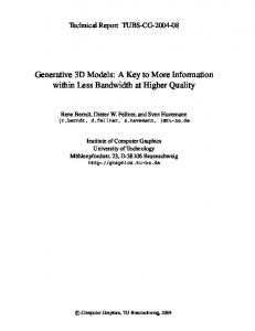
Fig. 1. Block diagram of the encoder for a 3-D graphic model.
data can quickly propagate due to the irregular grid structure and the use of the entropy coder. This affects the decoding of the subsequent connectivity information and causes a severe damage to the decoded mesh structure. Little research has been done in the error-resilient coding of 3-D graphic models before. An error-resilient component-based data partitioning scheme (CODAP) for the TS-based coding technique was proposed in MPEG-4 [20], [21]. Several mesh segmentation schemes [22]–[24] for error-resilient coding of 3-D graphic models were studied based on Li and Kuo’s constructive traversal coding technique [4], [5]. In this paper, we propose a new and efficient error-resilient scheme for the coding of arbitrary 3-D graphic models. This scheme also allows incremental rendering, with a reasonable bit-rate overhead. The block diagram of the proposed encoder is shown in Fig. 1. The basic idea of the proposed scheme can be stated as follows. 1) A 3-D graphic model is first partitioned in its connected components. An adaptive mesh segmentation algorithm, called the multi-seed traversal algorithm, is then used to partition the mesh structure of each connected component into a set of smaller pieces and their joint boundaries. Pieces are subsets of the original mesh structure of each connected component, and every piece contains some partial topology and geometry information of the original mesh. The pieces can be either simply or multiply connected, depending on the original mesh structure. The number of vertices in each piece is determined adaptively according to the target channel bit error rates (BER). The relationship between two neighboring pieces of a con-
nected component is represented by the “joint boundary,” which contains the information of common vertices and links. After mesh segmentation, there are four different types of data to be encoded for each connected component: the joint-boundary topology, the joint-boundary geometry, the piece topology, and the piece geometry. 2) A coding scheme is developed to encode the joint boundary and piece data of each connected component. The joint-boundary topology is efficiently coded by using the starting vertex id and the traversal direction. The joint-boundary geometry is encoded by using prediction and successive quantization. The piece topology is coded by using the constructive traversal method while the piece geometry is coded by using prediction and successive quantization. Since the joint-boundary topology and geometry information is necessary to stitch pieces back to obtain the original mesh in the presence of errors, it is protected by using the BCH error-correcting code. The bit-rate overhead introduced by BCH is very small as the joint boundary is only a small fraction of the total mesh data. 3) Appropriate headers and certain resynchronization words are inserted in coded joint boundaries and pieces of each connected component. Then, they are packed in independent units (called a segment) for transmission. This procedure is repeated to sequentially code each connected component of a 3-D graphic model. In order to achieve incremental rendering, data of each connected component are sent independently. Furthermore, data of all joint boundaries of a connected component are transmitted first, followed by data of all its pieces layer by layer.
862
IEEE TRANSACTIONS ON CIRCUITS AND SYSTEMS FOR VIDEO TECHNOLOGY, VOL. 11, NO. 7, JULY 2001
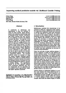
Fig. 2. Block diagram for the decoder of a 3-D graphic model.
At the decoder, four types of data of a connected component are extracted from the coded bit stream in a sequential order: the coded joint-boundary topology, the coded joint-boundary geometry, the coded piece topology, and the coded piece geometry. Since the joint-boundary data have been protected against channel errors, the topology and geometry information of anchor-vertices and anchor-links is mostly decoded correctly, and used in data recovery and error concealment during the decoding of piece-topology and piece-geometry data. All successfully decoded pieces are combined together by using a piecewise reconstruction procedure to form the connected component. Finally, all decoded connected components are assembled to reconstruct the target 3-D graphic model. The proposed error-resilient 3-D mesh decoding system is shown in Fig. 2. The model can thus be incrementally rendered, as the decoding procedure can start as soon as coded data of the first connected component is received. Although we have developed our scheme under the framework of Li and Kuo’s dual-mesh coding technique [4], [5], the basic error-resilient idea should be extensible to other 3-D compression schemes as well (with proper modifications to tailor to their specific implementations). Similar to CODAP [20], [21], our scheme partitions a 3-D mesh into pieces and joint boundaries, and packs the bit stream in independent data units called segments. Very small connected components are also grouped together to reduce overhead bits. However, our proposed scheme is more error resilient than CODAP, because we employ data recovery and error concealment at the decoder, which is not present in CODAP. Any piece corrupted by the channel error is simply discarded in CODAP, whereas we are able to recover many cor-
Fig. 3. Illustration of the multiseed traversal scheme by using two starting seeds X and Y, where pieces I and II as the resulting pieces and joint-boundary smoothing is illustrated via vertices A, B, C.
rupted pieces by using the joint-boundary information without introducing a significant bit-rate overhead. In fact, data recovery and error-concealment schemes in piece data have been made possible due to careful coding of joint-boundary data.
YAN et al.: ERROR-RESILIENT CODING OF 3-D GRAPHIC MODELS VIA ADAPTIVE MESH SEGMENTATION
Fig. 4.
863
Pieces of the Dinosaur model obtained by using the multiseed traversal algorithm.
Joint-boundary vertices and links are called “anchor-vertices” and “anchor-links,” respectively, since they form a skeleton in the 3-D space used for data recovery and error concealment in corrupted pieces. This paper is organized as follows. The adaptive mesh segmentation scheme is presented in Section II. The detailed encoding system is discussed in Section III. In Section IV, we focus on the decoding scheme with error detection, data recovery, and error concealment. Section V describes the piecewise-reconstruction scheme. Experimental results are shown in Section VI and conclusions are given in Section VII. II. ADAPTIVE MESH SEGMENTATION The topology structure of a 3-D graphic model may contain more than one connected components of different sizes. It is often necessary to partition large components into several pieces for better error resiliency. Many mesh partitioning schemes are available in the literature, including a software package developed by Karypis and Kumar [25]. In this work, we use an adaptive mesh segmentation scheme to extract pieces by considering both coding efficiency and error resiliency. It consists of three major modules: the piece-size determination, the piece extraction and the joint-boundary construction. A. Determination of Piece Size We adaptively determine the piece size in terms of the number of vertices based on target BER. Generally speaking, when the BER is high (or low), the piece size should be smaller (or larger). The piece size is chosen in power of 2, i.e., 32, 64, 128, etc. The minimum size is set to 32 to avoid a very high overhead. To achieve good error resiliency, the piece size is chosen to allow only 1 bit error in coded topology data of ten or more pieces. In Li and Kuo’s coding scheme [4], [5], the coding of topology data of an arbitrary 3-D mesh requires an average of 2 bits/vertex. Therefore, there would be 1 bit error for every 500 vertices of a . For the piece size of coded mesh statistically at a BER of 32, there would thus be an average of one bit error in 15 pieces. Please note that this is a very conservative estimate. In fact, the encoded topology bit stream of each piece can tolerate more than one bit errors, provided they are properly distributed, as discussed later in Section IV-C. B. Piece Extraction Pieces are extracted exclusively, i.e., no two pieces share the same polygon. The union of polygons of all pieces form the
complete polygon set of the connected component (or the original model). We represent the original 3-D polygonal mesh by using set of all vertices (geometry position and vertex of all polygons (indices of vertices) of the index) and set into pieces , mesh. We divide mesh is characterized by and , as discussed below. where Here, the union of (or ) is equal to (or ). Multiseed Traversal Algorithm: Conceptually, this algorithm is similar to simultaneously burning fires from all starting seeds, which would grow uniformly toward their respective neighborhood until all polygons and vertices of the whole mesh are burnt. Each traversed region is called a piece. To divide a connected component into pieces, vertices are first chosen are as starting seeds. Polygons associated with each seed found by using Li and Kuo’s constructive traversal scheme [4], [5], and stored in the corresponding polygon set . For each polygon set , vertices on the contour of all its polygons are stored in the corresponding vertex set . For all vertices in the vertex set , their associated polygons, which have not already been stored in any polygon set, are then found and stored in the corresponding polygon set . This procedure is repeated until all polygons of the connected component have been stored. The polygon sets and their associated vertices form resulting pieces. Fig. 3 illustrates the multiseed traversal scheme by using two starting seeds “X” and “Y.” First, seed “X” traverses all polygons marked by “a,” and seed “Y” traverses all polygons marked by “1.” Vertices lying on the contour obtained from seeds X and Y are represented by “ ” to “ ” and “ ” to “ ,” respectively. Polygons belonging to vertices “ ” to “ ” and vertices “ ” to “ ” are then traversed and represented by alphabet and numeral , respectively. This process continues until all polygons are traversed. Two pieces are thus formed. Seed Selection: The selection of starting seeds is critical in the multiseed traversal algorithm. If two seeds are selected too close to each other, their associated pieces could be much smaller than others. This will degrade coding efficiency due to a higher bit-rate overhead resulting from a poor data partitioning procedure. To obtain pieces of a uniform size, we select one seed at a time and each new seed is chosen to be the vertex with the farthest distance from the set of seeds that are already chosen. Fig. 4 shows four nearly uniform-sized pieces of the Dinosaur model obtained with this scheme. Correction of Irregular Structure: Some pieces generated by the above algorithm may have an irregular structure. A piece is assumed to have an irregular structure when its three or more boundary links are connected to one vertex. In Fig. 5(a), seven
864
IEEE TRANSACTIONS ON CIRCUITS AND SYSTEMS FOR VIDEO TECHNOLOGY, VOL. 11, NO. 7, JULY 2001
Fig. 5. Illustration of the irregular piece structure and its correction procedure: (a) irregular structure and (b) pieces after correction.
only knowing the topology and geometry information of all pieces. The importance of joint boundaries lies in that they can correct erroneous decoding of data in each piece when there are errors in the corresponding bit stream. The coding of joint-boundary information, however, contributes to the bit-rate overhead. To lower the overhead, we use a simple smoothing scheme, which reduces the number of vertices at the joint boundary, while keeping the mesh segmentation result nearly the same. In this scheme, if two nonconsecutive anchor-vertices on the joint boundary also have a direct link which lies inside a piece, this link can be used to substitute the sequence of links between these two anchor-vertices along the joint boundary. For example, the original joint boundary in Fig. 3 has anchor-links (A, B) and (B, C). Since there is also a direct link (A, C) between anchor-vertices A and C in Piece II, we substitute anchor-links (A, B) and (B, C) by link (A, C) and shift polygon (A, B, C) from Piece II to Piece I. III. ERROR-RESILIENT ENCODING SCHEME
polygons connected to vertex “A” have been divided in three pieces; namely, 1, 2, and 3. These polygons are ordered in a clockwise manner and identified by their piece ID. Here, Piece “1” has an irregular structure because its four boundary links are connected to vertex “A.” Ideally, polygons of the same piece should appear continuously. However, the fourth “1” is not continuous, and it should be reassigned to Piece “2,” as shown in Fig. 5(b). Fig. 6 shows pieces of the Dinosaur model before and after irregular-structure removal. Sometimes, the last piece of a connected component may consist of several nonconnected small parts. In such a case, only the biggest part is retained as the last piece, and all other parts are assigned to appropriate pieces. This procedure also avoids the creation of holes in some pieces during segmentation. The multiseed traversal algorithm, along with seed selection and irregular structure removal, allows pieces to grow uniformly around their associated starting seeds. As a result, the number of vertices on boundary is only a small fraction of the piece size. For example, we get an average of 7 and 10 joint-boundary vertices for a piece size of 32 and 64, respectively, for the Dinosaur model. Pieces obtained by using this scheme can be simply or multiply connected, depending on the original mesh structure of the connected component. C. Joint-Boundary Construction Two adjacent pieces share a number of vertices and links on their joint boundary. Sometimes, there may be more than one joint boundary between two adjacent pieces. We do not allow any polygon in the joint boundary. Special care has been taken in mesh segmentation to make sure that the joint boundary does not contain any nonconnected vertex. As a result, the joint boundary is composed of vertices that are linked one by one to form a 3-D curve. The curve is closed if the last vertex is connected to the first vertex. A hole inside a multiply connected piece is not considered a part of the joint boundary unless it is also shared by other adjacent piece. Joint boundaries are used to stitch different pieces together. In an error-free environment, the original mesh can be successfully constructed without joint-boundary information by
As shown in Fig. 1, four types of data (i.e., the joint boundary topology, the joint boundary geometry, the piece topology and the piece geometry, in that order) are encoded separately. The same joint boundary and piece coding schemes are used for simply, as well as multiply, connected pieces. Gueziec et al. [9] proposed an efficient method to encode the joint boundary information by applying run-length coding to consecutive pairs of boundary edges and using the order of traversal of vertices to determine vertex indices, which are usually costly to encode. In our scheme, vertices and links on the joint boundary are used to detect and conceal errors occurring in related pieces. In other words, our joint boundary coding method is developed to support error resiliency. The BCH error-correcting code is used to further protect joint boundary data against channel errors. There is no protection on coded piece data. The encoding system is described below. A. Encoding of Joint Boundary Topology We use the following structure to code the joint boundary topology: [PIECE ID 1][STARTING VERTEX ID 1] [TRAVERSE DIRECTION 1] [PIECE ID 2] [STARTING VERTEX ID 2][TRAVERSE DIRECTION 2] [CURVE OPEN/CLOSED] In the above, [PIECE ID 1] and [PIECE ID 2] specify the two pieces connected by the current joint boundary. Each PIECE ID is represented by either one or two bytes. We reserve the first bit to indicate this information. If the first bit is 0, the PIECE ID occupies 1 byte, and the maximum number of pieces that can be . This is enough for most 3-D graphic represented is models. If the first bit is 1, the PIECE ID is represented with 2 bytes. The maximum number of pieces allowed is thus enlarged . This is used for extremely complicated models to which have millions of vertices and polygons. [STARTING VERTEX ID 1] and [STARTING VERTEX ID 2] specify the corresponding index of the first stitching vertex
YAN et al.: ERROR-RESILIENT CODING OF 3-D GRAPHIC MODELS VIA ADAPTIVE MESH SEGMENTATION
(a)
865
(b)
Fig. 6.
Two pieces of the Dinosaur model before and after irregular structure correction. (a) Irregular structure. (b) Corrected structure.
Fig. 7.
Illustration of the coding of joint boundary data, where the relationship between the polygon normal and the traverse direction is also shown.
in these two pieces. Both starting vertices in fact represent the same vertex in the original model. However, they may have different indices in these two adjacent pieces. The number of bits to represent [STARTING VERTEX ID] is determined by the piece size, which is related to the BER. Our experiments reveal that the actual piece size deviates from its target value but never exceeds twice of its value. Thus, we need 6 (or 10) bits to represent the [STARTING VERTEX ID], when target piece size is 32 (or 512). [TRAVERSE DIRECTION 1] and [TRAVERSE DIRECTION 2] specify the direction to traverse boundary links in each piece in order to stitch remaining vertices one by one, according to the decoded geometry data of joint boundary. A boundary vertex in a piece has two boundary links. Each
boundary vertex can traverse the piece in two directions, depending on its associated polygon normal. [TRAVERSE DIRECTION] thus needs 1 bit to indicate the direction of traversal. Consider the case that a polygon normal points from the center of the polygon toward our eyes as shown in Fig. 7. Then, if the direction of its links is in the clockwise order, it is set to 1. Otherwise, it is set to 0. [CURVE OPEN/CLOSED] is represented by 1 bit. Other necessary information, such as the number of vertices in the joint boundary, is added during data partitioning, which is discussed later in Section III-E. Let us use an example to illustrate the scheme described above. As shown in Fig. 7, two pieces—5 and 8—are connected by the joint boundary. The index of the starting vertex is 26 and 32 in pieces 5 and 8, respectively. The traversing direction
866
IEEE TRANSACTIONS ON CIRCUITS AND SYSTEMS FOR VIDEO TECHNOLOGY, VOL. 11, NO. 7, JULY 2001
in piece 5 is from vertex 26 to vertex 12 (i.e., counter-clockwise) with direction bit set to 0. The traversing direction in piece 8 is from vertex 32 to vertex 47 (i.e., clockwise) with direction bit set to 1. By using 1 byte to represent [PIECE ID] and 6 bits to represent the [STARTING VERTEX ID], we have the following fixed length representation of the joint boundary in binary format: [PIECE 5][STARTING VERTEX 26][COUNTER CLOCKWISE][PIECE 8] [STARTING VERTEX 32][CLOCKWISE][CURVE OPEN]. In this example, it is 00 000 101 011 010 0 00 001 000 100 000 1 1 (31 bits in total). The coded data are protected against channel errors by using the BCH (63, 51, 5) code, which can correct up to two bit errors in a 63-bit block [26], [27]. The number of actual message bits in a block is 51. Since the information of the joint boundary topology is only a very small fraction of the total mesh data, the bit-rate overhead due to the BCH code is very small. Thus, an even stronger error-protection scheme, such as BCH(63, 45, 5), can also be used without introducing much overhead. It is confirmed by extensive experimental results that the above fixed length representation of the joint boundary topology can uniquely and correctly stitch two adjacent pieces together. B. Encoding of Joint Boundary Geometry To encode the joint boundary geometry, we adopt a technique that is similar to the coding of the geometry of pieces to be discussed later in Section III-D. In this technique, successive quantization and entropy coding are applied to vertex prediction residuals. Since joint boundaries are composed of only vertices and links, we consider a simple yet efficient vertex prediction scheme to compute the vertex residue. The joint boundary shown in Fig. 8(a) is composed by vertices 1, 2, 3, 4, 5, and links (1, 2), (2, 3), (3, 4), (4, 5), etc. The position of vertex 1 is coded with its actual coordinates. Predicted positions of vertices 2, 3, and 4 are denoted by points 2 , 3 and 4 , respectively. In this example, 2 is the same as vertex 1, 3 is the mirror point of vertex 1 with respect to vertex 2, and 4 is the mirror point of vertex 2 with respect to vertex 3, etc. Each quantized bit-plane contributes to the final position of vertices. Since only the first several bit-planes play a more important role in the vertex position, we apply the BCH(63, 51, 5) code only to the most significant three bit-planes to protect them against channel errors while encoding the remaining bit-planes directly. Again, the bit-rate overhead due to the use of BCH codes is very small.
(a)
(b) Fig. 8. (a) Vertex prediction rule for the coding of joint boundary geometry . data. (b) Constructive traversal of a mesh from single node
N
cases for the end node. If the end node is traversed for the first time, the corresponding link is called the branch and the end node is pushed to the queue of the next level. However, if the end node has been traversed before, the corresponding link is called the merger and the end node is marked. This end node is not pushed into the queue. Throughout the traversal, each link is visited once and only once. The traversal continues until all nodes and links are exhausted. Each link visited during traversal can be a branch or a merger depending on the type of its end nodes. The valence of the end node of each branch is recorded. For a merger, the index id of the end node and the position of the link is required. Both of them are efficiently represented by exploiting the neighboring topology. The symbols are then encoded by an adaptive binary arithmetic coder. Fig. 8(b) shows the traversal of the mesh growing from the up to the fourth level, where each node of single node the graph is labeled by two subscripts. That is, serves as the level index while is the order index in the queue of that level. For this example, all links traversed in the first and second levels and are branches. Links denoted by dashed lines are mergers at the third level.
C. Encoding of Piece Topology The topology of each piece is coded by using the constructive traversal method [4], [5]. With this method, the mesh is traversed level by level. Each level has a queue of nodes, which is initially empty and filled by the traversal process of the previous level. The queue of the first level consists of a single node randomly chosen from the mesh. At each level, one node is popped at a time from the queue. Then, each unvisited link of the node is traversed one by one in clockwise or counterclockwise order. For each such link, the first node is called the start node whereas the other node is called the end node. There are two different
D. Encoding of Piece Geometry The geometry data of each piece are encoded via three steps: local vertex position prediction, successive quantization, and entropy coding [4], [5]. Usually, strong local correlation exists between positions of adjacent vertices. Vertices are usually arranged in a certain order so that the local relationship among vertices can be described and exploited more efficiently. The vertex data prediction procedure predicts the current vertex position locally based on neighboring vertices and generates a sequence of prediction residues as a result. This prediction process
YAN et al.: ERROR-RESILIENT CODING OF 3-D GRAPHIC MODELS VIA ADAPTIVE MESH SEGMENTATION
is causal. With this method, the decoder can decode data correctly in an error-free environment. Then, a successive quantization scheme is applied to prediction residues. It adopts a sequence of gradually refined quantization steps instead of a single quantization step. The quantization step size is refined so that coefficients are approximated by an increasing precision. For each quantization, a binary output is produced for each coefficient to record the quantization result. All symbols generated by using the same quantization step are then grouped together to form a bit-plane in this level. This embedded coding scheme can encode a mesh with a progressive resolution which meets any specific bit budget easily. At the final step, an entropy coder (i.e., the arithmetic coder) is used to encode bits in the bit-plane according to a certain scanning order. E. Data Partitioning We have used a data-partitioning technique for joint boundary and piece data to limit the error-propagation effect to the current encoded unit only. In our design, the encoded topology data of all joint boundaries of a connected component are packed together. This helps in arranging the data in suitable length blocks (51 message bits per block) for applying the BCH(63, 51, 5) code. Each unit is preceded by headers that identify the joint boundary sequence number in the connected component and the number of coded bits and vertices in each joint boundary along with other necessary information. The encoded geometry data of all joint boundaries of the connected component are packed in the same fashion and suitable headers are applied. Each type of data is preceded by a unique 2-byte resynch word. The coded topology or geometry data of each piece in a connected component is treated as an independent coded unit (i.e., a segment). Each segment has its own 2-byte resynchronization word and header. The header information contains important segment parameters such as the segment length, the piece sequence number, the number of coded vertices, etc. The resynch word, the header, and the encoded data of each segment together are always made byte-aligned. It is assumed that the channel is binary symmetric and the header and resynch words are free of channel error. In a binary symmetric channel, an error in a segment of bit stream causes reversal of one bit. The resynch word and the header help in distinguishing a segment from other segments and identifying segments that have been corrupted by channel errors.
IV. ERROR-RESILIENT DECODING SCHEME As shown in Fig. 2, the four types of data of each connected component (i.e., the coded joint boundary topology, coded joint boundary geometry, coded piece topology, and coded piece geometry, in order) are extracted from the coded bit stream. The joint boundary topology and geometry data of each connected component are decoded first. Note that BCH(63, 51, 5) can al. most always correct channel errors for BER up to Coded data of some pieces might be corrupted by channel errors, since they are not well protected against channel errors. Techniques of error detection, recovery, and concealment are, however, applicable by using the information of anchor vertices
867
and links of the joint boundary. After decoding data of the current connected component, the other connected components are decoded one by one by following the same procedure. A detailed description of the decoding system is given below. A. Decoding of Joint-Boundary Topology The topology of a joint boundary is encoded by using the fixed length representation. As discussed in Section III-A, for a graphic model of a moderate size at BER of , the length of coded joint-boundary topology data is only 31 bits. Forward error correction will add several more bits to it. Due to error protection, the joint boundary topology can be decoded free of error in most cases. The decoded topology data shall provide us sufficient information about the two adjacent pieces, such as starting vertices and traversal directions for stitching them together. B. Decoding of Joint-Boundary Geometry The geometry of the joint boundary has been encoded by using a linear vertex prediction and by applying successive quantization and entropy coding to the prediction residual. Compared with the number of vertices in two adjacent pieces, the number of vertices in the joint boundary is only 10% to 20%. Due to the use of error-correction codes, the first three bit-planes of geometry data can be decoded free of error in most cases. Since the position of joint boundary vertices can be roughly located by using the first three bit-plane values, errors in the remaining bit-planes do not have much impact on the final positions of these vertices, and cracks can be avoided. We treat these vertices and links in the joint boundary as fixed in the 3-D space, and use them as anchor vertices and anchor links in the subsequent decoding of the piece topology and the piece geometry for error recovery and concealment, respectively. C. Decoding of Piece Topology and Data Recovery The topology of each piece has been encoded by using the constructive traversal scheme and the entropy coder. The constructive traversal scheme generates a sequence of symbols of branch and merger. Each of these symbols is critical in the decoding procedure to reconstruct the topology. However, the entropy coder is very sensitive to errors, and even one bit error may corrupt several branch or merger symbols and their property information, such as the vertex valence information for a branch, the vertex index information for a merger, etc. This would result in holes, broken links or unconnected vertices in the decoded mesh. Error detection and concealment is thus necessary to correctly reconstruct the corrupted mesh. 1) Error Detection: The presence of errors in the bit stream of piece topology can be easily detected by using the following three criteria: 1) broken links or unconnected vertices are found; 2) anchor links do not match with the corresponding links in the decoded mesh; and 3) the number of vertices in the decoded mesh does not match with that stored in the corresponding segment header. If none of the above three situations occur, the piece is treated as error free. We have observed that an error in the encoded bit stream almost always results in a mismatch between anchor links and
868
IEEE TRANSACTIONS ON CIRCUITS AND SYSTEMS FOR VIDEO TECHNOLOGY, VOL. 11, NO. 7, JULY 2001
Fig. 9. Error-detection and recovery procedure for the decoding of the: (a) piece-topology bit stream and (b) piece-geometry bit stream.
their corresponding links in the decoded mesh, due to the following reason. In our mesh segmentation scheme, the starting seed is normally located close to the center of the piece, which is usually far from its joint boundaries. As a result, vertices on joint boundaries are normally traversed later than intermediate vertices. Here, the term intermediate represents all the vertices of a piece other than anchor vertices. Therefore, errors in the encoded bit stream would propagate with traversal and the decoding procedure should easily find errors in anchor vertices. This type of error appears in the form of anchor-link mismatch. To more clearly explain the anchor-link mismatch, let us consider the relationship between a piece and its joint boundary. The geometry information of each anchor vertex is coded three times during the encoding procedure, i.e., once in the joint boundary and twice in the two adjacent pieces. During the decoding of a piece, if the decoded vertex is identified as an anchor vertex, then decoded links associated with it in the piece will be compared with its anchor links. A mismatch indicates the presence of errors. The following example is helpful in illustrating the above discussion. As shown in Fig. 7, vertex 32 in piece 8 is an anchor vertex. It is connected to anchor vertex 47 by the anchor link (32, 47). Anchor vertex 47 is also connected to anchor vertex 17 by an anchor link (47, 17). Let us assume that vertex 47 has been correctly decoded and identified as an anchor vertex during the decoding of piece 8. All links associated with it will be compared with anchor links (47, 32) and (47, 17). If link (47, 17), for example, is found missing in piece 8, we know that some error has occurred and a data recovery procedure should be adopted to recover the corrupted data, as explained below. Please note that this data recovery procedure is not simply adding link (47, 17), which can introduce other defects.
2) Data Recovery: During decoding of the coded piece-topology bit stream, anchor vertices are decoded one by one. Between the decoding of two anchor-vertices, their associated intermediate vertices are also decoded. In Fig. 9(a), , and , anchor-vertices are denoted by up respectively, according to their decoding order. If are decoded correctly and a mismatch is detected to vertex , we know that in the anchor link associated with vertex some error has occurred in the portion of the bit stream, which and . Data recovery lies between the decoding of can be achieved by flipping bits in this portion one at a time, to until and repeating the decoding process from . After this, we get the correct anchor-link information for we can proceed with the decoding process from the next anchor onwards. vertex The above data recovery scheme is based on the following two assumptions. First, there is only 1 bit error inside the corrupted portion of the bit stream. The probability of more than one bit error is minimized by adaptively choosing the piece size in Section II-A according to target BER. Second, the length of this portion is not too long so that the computation time is reaof the sonable. The size of the corrupted portion is around piece-topology bit stream, where is the number of anchor vertices that is usually about 10%–20% of the piece size. We have observed that there is normally one anchor-vertex after every 4–9 intermediate vertices, in our coding scheme, which corresponds to about 10–20 bits in the corresponding bit stream portion. If there are two bit errors in a portion of the bit stream of piece topology, successful data recovery requires the flipping of an arbitrary combination of any 2 bits in this portion to explore all error possibilities. To avoid the computational overhead, we simply treat such piece as nondecodable.
YAN et al.: ERROR-RESILIENT CODING OF 3-D GRAPHIC MODELS VIA ADAPTIVE MESH SEGMENTATION
It is clear from the above discussion that the main role of the joint boundary data is to help identify errors in the coded piece-topology data. The error is corrected by flipping bits in the corrupted portion. As long as the encoding and decoding algorithms for the individual piece work well on both simply and multiply connected cases, error-detection and -correction schemes will also work well. This is also true for the coded piece-geometry data to be discussed below. D. Decoding of Piece Geometry and Error Concealment The geometry of each piece is encoded by applying successive quantization and entropy coding to the prediction residue. If we use 20 bit-planes, the average number of bits per vertex for geometry data is 20, which is much larger than the average 2 bits per vertex for topology data. As a result, errors would occur more often in the coded geometry bit stream as compared to the topology bit stream at the same BER. However, the effect of an error in geometry data is not as critical as that in topology data. 1) Error Detection: In most cases, errors in the coded bit stream of piece geometry can be detected by using the following two criteria. First, nonzero bits are left in the coded bit stream, after decoding of the required number of vertices, as specified in the corresponding segment header. Second, the positions of anchor vertices in joint boundaries do not match with the corresponding vertices in the decoded mesh. Errors in several most significant bit planes will have more impact than those in the remaining less significant ones. Furthermore, a bit error introduced in a bit- plane will corrupt all subsequent codewords in that bit plane. The decoding of the first (or the second, the third) bit plane of a coded bit stream of the piece geometry is shown in Fig. 9(b). In each bit plane, anchor vertices are sequentially decoded one by one. The associated intermediate vertices lying between these two successive anchor vertices are also simultaneously decoded. A decoded bit “1” indicates that the residue of the current vertex is higher than the threshold of the current bit-plane. In the decoding procedure, the decoded value of an anchor vertex is compared with the threshold for the current bit-plane and the actual value of the corresponding anchor vertex. Errors can be easily detected if there is a contradiction. For example, let us assume that anin Fig. 9(b) has a value 1.5, and the threshold chor vertex for the current bit-plane is 1.2. If the decoded bit for this vertex is “1,” there is no contradiction. Otherwise, the data contain errors. 2) Error Concealment: We adopt an error-concealment scheme only for the first 3 bit-planes of piece geometry, because errors in the remaining bit-planes will only marginally distort the final decoded mesh. If decoded results of an anchor vertex , until in Fig. 9(b) have no contradiction between their actual value and the threshold but there exists a , an error is detected to lie contradiction for anchor vertex . Note that this is different from the data recovery before procedure used to correct errors in the piece topology, where an error was claimed to be in the bit stream portion lying between and . It is possible that errors in the piece geometry occurred before this portion, yet we got a correct decoded . Since the decoded bit is either “1” or “0,” the value of probability that errors are not in this portion is 1/2. To reduce
869
the probability of a false alarm, we assume that the error is located in the bit stream portion lying between decoding of and . Thus, the probability that the error location is outside this portion is reduced to 1/16. Similar to the error recovery discussed before, error concealment of the piece geometry is achieved by flipping bits one by one in the located bit stream portion. We have observed that 1 bit error in each portion of a bit plane of the piece-geometry data can be corrected most of the time. No error concealment is attempted when there are more than one bit error in our current scheme. V. PIECEWISE RECONSTRUCTION After the decoding procedure, most or all pieces can be decoded successfully. The topology of each successfully decoded piece is free of error. The geometry of some successfully decoded pieces may, however, be distorted, depending on the channel BER. We stitch all recovered adjacent pieces to form the mesh structure of the connected components by using anchor vertices and anchor links, as discussed below. 1) Collect all successfully decoded pieces of a connected component, and record their piece sequence number. 2) Collect all joint boundaries. Based on the joint boundary information, mark each piece that has a joint boundary with other pieces. 3) Put unmarked pieces, which represent small connected components, in the final mesh directly. 4) For each joint boundary, look for its two adjacent pieces. If only one of them is successfully decoded, no further action is needed. If both are available, search each piece to find the starting stitching vertex, and traverse along the traversing direction to stitch vertices one by one. It is possible that the position of an anchor vertex has different decoded values in the joint boundary and two adjacent pieces due to uncorrected channel errors in less significant bit-planes (other than the first three most significant bitplanes). If this occurs, use anchor vertex value in the joint boundary. 5) Repeat Step 4 until all joint boundaries are explored. Put all stitched pieces in the final mesh. The connected component is thus formed. 6) Combine all connected components to reconstruct the 3-D graphic model. VI. EXPERIMENTAL RESULTS We applied the proposed error-resilient coding scheme to 12 test models at different random and burst BERs. Burst errors have been generated by using the 2-state Markov model as done in MPEG-4. We have assumed a bit-rate of 32 kbits/s and the burst BER is 0.5. The transmission channel was assumed to be binary symmetric, and there was no loss of an entire packet as synchronization words and headers are free of errors. Two original test models “Spock” and “Dinosaur” are given in Fig. 10 while reconstructed models at random BER of are shown in Fig. 11. We see from these two figures that reconstructed models are almost identical to original ones. Reconare shown in Fig. 12, structed models at a random BER of
870
IEEE TRANSACTIONS ON CIRCUITS AND SYSTEMS FOR VIDEO TECHNOLOGY, VOL. 11, NO. 7, JULY 2001
Fig. 10.
Original graphic models of Spock and Dinosaur.
Fig. 11.
Reconstructed graphic models for Spock and Dinosaur with BER equal to 10
.
Fig. 12.
Reconstructed graphic models for Spock and Dinosaur with BER equal to 10
.
which have fair visual quality. Figs. 11 and 12 represent cases where the topology and the three most significant bit planes of all pieces are correctly decoded/recovereded. The deterioration in the quality of reconstructed models as shown in Fig. 12 with
an increase in BER is due to uncorrected errors in remaining less significant bit planes of the piece-geometry data. If the topology of one or more pieces cannot be decoded successfully, there would be some holes in the reconstructed model.
YAN et al.: ERROR-RESILIENT CODING OF 3-D GRAPHIC MODELS VIA ADAPTIVE MESH SEGMENTATION
871
Fig. 13.
Reconstructed graphic models for Spock and Dinosaur with one piece not decodable for BER equal to 10
Fig. 14.
Reconstructed graphic models for Spock and Dinosaur with a distorted piece for BER equal to 10
Fig. 13 shows decoded models when one of their pieces is not . The hole, pointed to by an decodable with BER equal to arrow, appears dark in the figure. If the topology of all pieces is decoded correctly while at least one out of the three most significant bit planes of a piece is not correctly decoded, the corresponding piece is still considered as decodable. But it will result in visible distortion in the reconstructed model. For example, see the area of the corrupted piece, as shown in Fig. 14 with BER . equal to For a given graphic model at a certain BER, the model success / , where is the number rate is defined as of times the experiment is repeated on the graphic model and is the number of times the whole model is successfully decoded, i.e., all its piece-topology segments are correctly decoded. In Table I, we show the success rate for five test graphic is 500 for each BER. For models at different BERs, where . the Dinosaur model, the success rate is 100% at BER of , the decoding system fails to get the When the BER is complete model only six times, and the success rate is 98.8%. , the number of failures increases to 82, When the BER is
, where the arrow points to the missing piece.
, where the arrow points to the distorted piece.
and the success rate drops to 83.6%. The success rate drops to zero when the BER is equal to . For this case, there is at least one piece-topology segment that has more than 1-bit uncorrectable error each time. The model success rate described above is highly conservative because the model can still be reconstructed when some pieces are not decodable, as shown in Fig. 13. To evaluate the decoding performance more realistically, we adopted another measure, i.e., the piece success rate, which is the ratio of the number of successfully decoded pieces divided by the total number of pieces to be decoded. Experimental results for five graphic models are given in Table I. The experiment was repeated 500 times for each BER. For the Dinosaur model, . When BER the piece success rate is 100% for BER of , the number of total pieces to be decoded for all 500 is experiments is 4000, and the decoding system fails to decode only 6 pieces. The piece success rate is therefore 99.9%. When , the number of failed pieces is 148 out of 30 000 BER is pieces, and the piece success rate is 99.5%. Even when BER , 72.1% of the pieces can be successfully decoded. is
872
IEEE TRANSACTIONS ON CIRCUITS AND SYSTEMS FOR VIDEO TECHNOLOGY, VOL. 11, NO. 7, JULY 2001
TABLE I SUCCESS RATE FOR GRAPHIC MODELS DIFFERENT RANDOM BERs
AT
models is given in Table IV. We observe that the bit-rate overhead normally increases as the size of the graphic model becomes smaller and/or BER increases. The bit-rate overhead is comparable to that of the error-resilient CODAP technique developed in MPEG-4 [21]. VII. CONCLUSION
TABLE II SUCCESS RATE FOR GRAPHIC MODELS AT DIFFERENT BERs FOR AN AVERAGE BURST LENGTH OF 1 MS
TABLE III SUCCESS RATE FOR GRAPHIC MODELS AT DIFFERENT BERs FOR AN AVERAGE BURST LENGTH OF 10 MS
TABLE IV BIT-RATE OVERHEAD FOR 12 TEST MODELS AT DIFFERENT BERs
An error-resilient coding system for 3-D graphic models was presented to exploit the topology and geometry information of the original mesh. The system can also incrementally render one connected component of the 3-D graphic model at a time. A multi-seed mesh traversal scheme was developed to segment a mesh into a set of smaller and uniform sized pieces. The piece size is determined according to the channel BER. However, the scheme still performs well even when the piece size is not adapted. In that case, pieces that are affected by multiple channel errors at high BERs may not be successfully decoded sometimes. Different pieces are connected via their joint boundaries. Since joint boundaries form the basis in data recovery of the piece topology and error concealment of the piece geometry in the presence of channel errors, an error-resilient coding scheme of joint boundaries was carefully developed. The probability of joint boundary data to be hit by channel errors is low because the coded joint boundary data are only a small fraction of the total bit stream. Therefore, a higher protection of joint boundary data against channel errors introduces only a small amount of overhead. It was demonstrated that the proposed system can achieve very good error resiliency in the presence of random and burst errors, with an overhead comparable to that of CODAP in MPEG-4. Although the bit-rate overhead due to the coding of joint boundary data is small, we would like to investigate techniques to further improve the mesh segmentation algorithm so that it is adaptive to the shape of the graphic models. In other words, mesh segmentation can be carried out according to semantic details of the underlying graphic model. This will make error recovery and concealment tasks easier. REFERENCES
Piece success rates for an average burst error length of 1 and 10 ms are given in Tables II and III, respectively. We see that the success rate depends mainly on target BER and varies very little for different models at a given BER level. To calculate the coding cost (i.e., the overhead in terms of bits per vertex) in comparison with Li and Kuo’s error-free coding scheme [4], [5], we used 12 MPEG-4 graphic models to be representatives of large-, medium-, and small-sized models. The percentage of the bit-rate overhead for these 12 graphic
[1] M. Deering, “Geometric compression,” in Computer Graphics Proc.—Annu. Conf. Series, Aug. 1995, pp. 13–20. [2] G. Taubin and J. Rossignac, “Geometry compression through topological surgery,” ACM Trans. Graphics, vol. 17, 1998. [3] G. Taubin, W. P. Horn, F. Lazarus, and J. Rossignac, “Geometry coding and VRML,” Proc. IEEE, vol. 86, pp. 1228–1243, June 1998. [4] J. Li and C.-C. J. Kuo, “Compression of mesh connectivity by dual graph approach (M1),” in MPEG-4 Tokyo Meeting, 1998, Contribution Doc. M3324. [5] , “Progressive coding of 3D graphic models,” Proc. IEEE, vol. 86, pp. 1052–1063, June 1998. [6] C. Touma and C. Gotsman, “Triangle mesh compression,” in Proc. Graphics Interface, June 1998. [7] S. Gumhold and W. Strasser, “Real time compression of triangle mesh connectivity,” in Computer Graphics Proc.—Annu. Conf. Series, 1998. [8] J. Rossignac, “Edgebreaker: Connectivity compression for triangle meshes,” IEEE Trans. Visual. Comput. Graphics, vol. 5, pp. 47–61. [9] A. Gueziec, F. Bossen, G. Taubin, and C. Silva, “Efficient compression of nonmanifold polygon meshes,” in Proc. IEEE Visualization ’99, Oct. 1999. [10] R. Bar-Yehuda and C. Gotsman, “Time/space tradeoffs for polygon mesh rendering,” ACM Trans. Graphics, vol. 15, pp. 141–152, Apr. 1996.
YAN et al.: ERROR-RESILIENT CODING OF 3-D GRAPHIC MODELS VIA ADAPTIVE MESH SEGMENTATION
[11] J. Cohen, A. Varshney, D. Manocha, G. Turk, H. Weber, P. Agarwat, F. Brooks, and W. Wright, “Simplification envelopes,” in Computer Graphics Proc.—Annu. Conf. Series, Aug. 1996, pp. 119–128. [12] W. J. Schroeder, “Decimation of triangle meshes,” in Computer Graphics Proc.—Annu. Conf. Series, July 1992, pp. 65–70. [13] H. Hoppe, T. DeRose, T. Duchamp, J. McDonald, and W. Stuetzle, “Mesh optimization,” in Computer Graphics Proc.—Annu. Conf. Series, Aug. 1993, pp. 19–26. [14] H. Hoppe, “Progressive meshes,” in Computer Graphics Proc.—Annu. Conf. Series, Aug. 1996, pp. 99–108. [15] P. Hinker and C. Hansen, “Geometric optimization,” in Proc. Visualization Conf., Oct. 1993, pp. 189–195. [16] A. Kalvin and R. Taylor, “Surfaces: Polygonal mesh simplification with bounded error,” IEEE Comput. Graphics Applic., vol. 16, pp. 64–77, May 1996. [17] J. Popovic and H. Hoppe, “Progressive simplicial complexes,” in Computer Graphics Proc.—Annu. Conf. Series, Aug. 1997, pp. 217–225. [18] A. W. F. Lee, W. Sweldens, P. Schroder, L. Cowsar, and D. Dobkin, “MAPS: Multiresolution adaptive parameterization of surfaces,” in Computer Graphics Proc.—Annu. Conf. Series, 1998. [19] A. Gueziec, “Surface simplification with variable tolerance,” in Proc. 2nd Annu. Int. Symp. Medical Robotics and Computer Assisted Surgery, Baltimore, MD, Nov. 1995, pp. 132–139. [20] Description of Core Experiments on 3D Model Coding, ISO/IEC JTC1/SC29/WG11, MPEG98/N2449, Oct. 1998. [21] M.-J. Han, M.-S. Song, S.-J. Kim, and E. S. Jang, “Results of M5 code-experiments,” ISO/IEC JTC1/SC29/WG11, MPEG98/M4516, Mar. 1999. [22] Z. Yan, S. Kumar, J. Li, and C. Kuo, “Error resilient coding of 3D graphics based on morphing and volume splitting,” in SPIE Int. Symp. Voice, Video and Data Communications, Boston, MA, Sept. 1999. , “Robust coding of 3D graphic models using mesh segmentation [23] and data partitioning,” in Proc. IEEE Int. Conf. Image Processing, Kobe, Japan, Oct. 1999. [24] Z. Yan, “Efficient and robust compression on 2D and 3D graphics,” Ph.D. dissertation, Dept. of Elect. Eng. Syst., Univ. of Southern California, Los Angeles, CA, Dec. 1999. [25] G. Karypis and V. Kumar. MeTis: A software package for partitioning unstructured graphs, partitioning meshes, and computing fill-reducing orderings of sparse matrices—Version 4.0, Univ. of Minnesota. [Online]. Available: http://www-users.cs.umn.edu/karypis/merits/metis.html [26] S. Lin and D. J. Costello Jr., Error Control Coding: Fundamentals and Applications. Englewood Cliffs, NJ: Prentice-Hall, 1983. [27] R. Morelos-Zaragoza. (1997) Error correcting codes page. [Online]. Available: http://imailab-www.iis.u-tokyo.ac.jp/roberts/codes.html
Zhidong Yan (M’01) received the B.S. degree in computer science and physics from Tsinghua University, Tsinghua, China, in 1995, the M.S. degree in electrical engineering and computer science, and the Ph.D. degree in electrical engineering from University of Southern California at Los Angeles in 1999. He is currently a Staff Engineer at Tornado Development Inc., Los Angeles, CA. His research interests include graphic, image, video, audio compression, wireless communication, and structure-level error resilience. His current research area is in streaming video and voice/speech recognition for mobile devices.
873
Sunil Kumar received the B.E. degree in electronics engineering from S.V. Regional College of Engineering and Technology, Surat, India, in 1988, the M.E. degree in electronics and control engineering, and the Ph.D. degree in electrical and electronics engineering, both from irla Institute of Technology and Science, Pilani, India, in 1993 and 1997, respectively. He served in the Electrical and Electronics Engineering Department, Birla Institute of Technology and Science, as a Lecturer from 1993 to 1997. Since August 1997, he has been pursuing post-doctoral research in the Department of Electrical Engineering-Systems, University of Southern California at Los Angeles. His research areas include image- and video-compression techniques, error-resilient techniques, and mobile multimedia networks.
C.-C. Jay Kuo (S’86–M’87–SM’92–F’99) received the B.S. degree from National Taiwan University, Taipei, in 1980, and the M.S. and Ph.D. degrees from Massachusetts Institute of Technology, Cambridge, in 1985 and 1987, respectively, all in electrical engineering. He was a Computational and Applied Mathematics (CAM) Research Assistant Professor in the Department of Mathematics, University of California at Los Angeles, from October 1987 to December 1988. Since January 1989, he has been with the Department of Electrical Engineering Systems and the Signal and Image Processing Institute, University of Southern California at Los Angeles, where he currently has a joint appointment as Professor of Electrical Engineering and Mathematics. His research interests are in the areas of digital signal and image processing, audio and video coding, media communication technologies and delivery protocols, and network computing. He has authored more than 400 technical publications in international conferences and journals. Dr. Kuo is the Editor-in-Chief for the Journal of Visual Communication and Image Representation, Associate Editor for IEEE TRANSACTIONS ON SPEECH AND AUDIO PROCESSING, and Editor for the Journal of Information Science and Engineering and the Journal of Applied Signal Processing. He served as an Associate Editor for IEEE TRANSACTIONS ON IMAGE PROCESSING during 1995–1998 and the IEEE TRANSACTIONS ON CIRCUITS AND SYSTEMS FOR VIDEO TECHNOLOGY during 1995–1997. He received the National Science Foundation Young Investigator Award (NYI) and Presidential Faculty Fellow (PFF) Award in 1992 and 1993, respectively. He is a member of SIAM, ACM, and SPIE.