M. Gazdek, S. Strelec, M. Rezo
Procjena poboljšanja tla kompresijskim seizmičkim valovima ISSN 1330-3651 UDC/UDK 624.138.22:624.154
ESTIMATION OF VIBRO REPLACEMENT BY COMPRESSION SEISMIC WAVES Mario Gazdek, Stjepan Strelec, Milan Rezo Preliminary notes The purpose of soil improvement by vibro replacement is a general increase in the mechanical properties of soil in the requested volume. Columns-soil contact contours are usually irregular so that the classical concept of a pile is partially lost, and the emphasis switches to the properties of the composite system. Variations of embedded gravel volume and compaction cause significant changes of the soil density and the elastic properties before and after the intervention, and they are sufficiently distinctive for profiling by compression P-wave refraction tomography. Therefore, the analysis of the soil improvement degree is focused on the differences of P-wave velocities of the test pile field and control field. The relative relationship of the condition variations before and after embedding can be well defined by the position and extension, while the velocity ratio vector quantifies the effect of improvement by depth along the whole field. The shape of variations coincides well with the vibrator operation protocol. Keywords: improvement control, P-wave velocity, refraction tomography, seismic waves, soil improvement
Procjena poboljšanja tla kompresijskim seizmičkim valovima Prethodno priopćenje Svrha bonifikacije tla ugradnjom šljunčanih pilota je općenito poboljšanje mehaničkih svojstava u zahtijevanom volumenu. Kontaktne konture pilot-tlo najčešće nisu oštre pa se klasični pojam pilota djelomično gubi, a težište se prenosi na svojstva spregnutog sustava poboljšanog tla. Varijacije volumena i zbijenosti ugrađenog šljunka uzrokuju promjene gustoće i elastičnih svojstava tla prije i poslije zahvata, a dovoljno su distinktivne za njihovo profiliranje kompresijskim P valovima refrakcijskom tomografijom. Zbog toga je analiza mjere poboljšanja tla u ovom radu usmjerena na razlike brzina P valova kroz izvedeno probno i kontrolno polje šljunčanih pilota. Relativni odnos promjene stanja prije i poslije ugradnje može se dobro definirati po položaju i pružanju, dok se vektorom vrijednosti omjera brzina u profilima kvantificira utjecaj poboljšanja po dubini duž čitavog polja. Oblik promjena se dobro poklapa s krivuljama protokola rada vibratora. Ključne riječi: brzina P vala, kontrola poboljšanja, poboljšanje tla, refrakcijska tomografija, seizmički valovi
1 Introduction Uvod Quality assurance and control of the bonification level of physical-mechanical properties have a crucial role in successful implementation of any soil improvement method. Soil improvement by gravel columns installation is not an exception, moreover it is interesting because of a possibility for verification with non-destructive surface seismic methods. The family of deep vibro techniques includes vibro compaction, vibro replacement and structural foundation elements construction [1]. Improvement criteria for all these methods can be finally set only in test fields. The test field establishes direct relations between designed and accomplished bearing capacity parameters of the foundation soil. If the values by the field-coupled parameters are within the given criteria limits, then there is no need for their separation. In other words, an execution parameter can be accepted as the design one, as long as the bonification processes that could change it are under control. However, execution parameters are not identical to designed geotechnical parameters by their form, but are instead typical values describing the installation process or the vibrator operation. The recorded data on time intervals and frequencies of particular penetration and compaction phases, corresponding depths, velocities, loads and used energy of a particular manoeuvre become geotechnical relevant only if the range of mechanical properties values of thus improved soil can be assumed reliable. Initially, parameters of soil improvement by installation of a gravel cylinder column (pile) are assumed. The initial model depends on the experience of equipment manufacturer, vibrator operator and geotechnical expert. Technical Gazette 18, 2(2011), 243-252
The most common control parameter is the limit pressure or the energy level for installation by depth, and it is monitored continuously during execution [2, 3], . Only when the level of change of some mechanical property value has been ascertained by direct tests, the respective initial model can be valid for the execution of gravel columns. In that sense, the results of seismic tomography by compression or P-waves can be used for control of the improvement, since they have a potential to quantify changes of mechanical properties, particularly of elastic moduli.
2 Gravel columns installation by vibro replacement technique Ugradnja šljunčanih pilota The application of vibro replacement yields to mechanical properties improvement, so that the foundation soil can fulfill the requirements relating to loading conditions, bearing, settlement, stability and liquefaction potential [4]. In the procedure, the cylindrical vibrator of two or more tons, 3-5 m long, is driven into the soil to the required depth. Then, depending on the selected method, the soil is continuously only compacted by rotation of the vibrator excentre (Vibrocompaction or Vibroflotation), or a column of stone or gravel aggregate is installed and compacted simultaneously (Vibro stone/gravel columns). The column can be also cemented. All the processes are of the ascending type. From the geotechnical viewpoint, induced vibrations in the specified range of influence cause rearranging of soil or of installed material grains whereby the compaction is increased [5]. The impact zone depends on the soil type, type of the vibrator, deep compaction method and the designed regime of operation. 243
Estimation of vibro replacement by compression seismic waves
An increase of compaction is proportional to the level of power consumption. If only the installation method is considered, it is important to point out that vibro replacement of the material is done in several steps that are repeated in each particular ascending sequence. Main operations of the vibrator during construction of a gravel column are in general: penetration of the vibrator into the soil to the designed depth and compaction of the material from the bottom up towards the surface. The vibrator is driven in with intermissions, in which surrounding soil is compacted and drained by lateral vibrations. Penetration and vibration are performed alternately and successively to the anticipated depth. The whole procedure takes approximately 10-20 seconds per meter [6]. The vibrator is then raised from the base level in cycles by 0,5-1,0 m to enable the gravel to fill the cavity between the bottom and the top of the vibrator. Gravel is subsequently compacted and driven into the soil laterally. A particular sequence lasts until the limit compaction pressure is achieved or until the required level of power for compaction is reached, i.e. two minutes at the most, regardless of the selected criterion [6]. The previous step is repeated in the ascending manner to the ground surface, so that the complete pile body is formed in that way. The magnitude of vibrations depends on specific properties of the test field, but the frequency of 25-30 Hz for amplitudes of 15-25 mm is regularly considered as the initial one [6]. Strictly taken, the effect of this method from the geotechnical point of view is not intended to increase compaction of the surrounding soil, but the improvement refers to the gravel body of greater stiffness and greater shear strength [7]. The possible improvement of the soil around piles can most often be confirmed by geotechnical surveying. The method for estimation of improvement factor, as the function of the internal friction angle and the ratio of areas of the affected surrounding surface and the pile cross-section, has been developed for gravel pile by numerical modeling using FE analysis [7].
3 Seismic methods of control Seizmičke metode kontrole Geophysical methods are common non-invasive surveying techniques for testing soil-gravel composite or improved soil, since very small deformations under the working load in the soil are expected (except in extraordinary cases) [8]. Spectral and multichannel analyses of surface waves (SASW and MASW), are usual seismic sounding or profiling methods for ascertaining the rate of average improvement of the soil stiffness properties [9, 10, 11]. In such geophysical surveys, the improvement level is defined as the ratio of the composite and basic soil shear moduli (moduli before and after the intervention) along profile lines. A satisfactory level of improvement is already shown even when arbitrary and different crosssections before and after the improvement are compared [9]. The stiffness properties of the composite soil from the results of such a survey may be compared with design assumptions. On the other hand, due to the newly-composed and complex stress state, the stiffness of the composite compound could hardly be determined from the distinct results of mechanical probes such as Becker BPT, cone CPT, dynamic cone DCPT and standard SPT penetration tests in the soil and piles (BPT was developed in particular 244
M. Gazdek, S. Strelec, M. Rezo
for the purpose of determining a correct number of the SPT blows in soils with a significant content of gravel [12]). Sensitivity of the shear wave velocities to a mechanical properties change is relatively high, so that the improvement of mechanical properties of soil is distinctive even if the differences in the densities of the composite and basic soil are neglected. That is the consequence of the fact that, in the domain of very small deformations (order of magnitude up to 0,001%), the ratio of shear modulus and a shear deformation is constant. Behavior of the geomedium is therefore linear elastic so that the results of seismic methods are relevant, and the change of shear modulus G is proportional to the square of shear velocity VS and density ρ (G = VS2 × r) . As a rule, such sensitivity is characteristic also for compression waves, so that the analysis of changes of mechanical properties could be justifiably carried out regarding the P-wave modulus M [13] ( M = VP2 × r , defined as the ratio of axial stress to axial strain in a uniaxial strain state). In short, by generating a seismic pulse or a transient dynamic load and by transfer of thus caused disturbance through the geomedium, a cluster of stress waves, which consists of the surface (Rayleigh's, R and Love's, L) and body (compression, P and shear, S) waves, can always be registered on the surface. In the engineering geophysics (seismic), all types of mechanical waves get undivided attention. However, there are still efforts to divide the complex spectra of waves into particular types (by the means of generation, by the type of the sensor or by the way of surveying and recording), more so as their velocities are directly connected to other elasticity constants (Young modulus E, bulk modulus K). The current tendency in applied surface seismic methods is achieving the greatest possible number of the sources and the sensors, because neither the length of the profile, nor the recording time is restrictive any more. The great amount of the recorded data, quick, different and complex numeric methods of interpretation have almost standardized the protocol of seismic surveys up to depths of 30 m. For example, P (vertical) generation of the seismic pulse and P sensors with sensitivity ≤ 10 Hz have proved satisfactory for specific demands too. In that way, with the sufficient density of source-sensor pairs, it is possible to make a posterior analysis of the seismic profile either by the multi-channel analysis of surface waves (MASW), or by refraction microtremor (ReMi) [14] or classical P refraction tomography. The shortcoming of refraction which is immanent to the assumption about the increase of the velocity gradient with the depth, in the analysis of the gravel piles test field can be minimized, because the geotechnical model is known. The tomographic interpretation can be defined specifically according to such structure of the seismic environment. Referring to the recommendations of Eurocode 7 (1997) [15] for design of piles with respect to the limit states, it is evident that the geotechnical parameters for designing may also be estimated by seismic methods [16]. Methods for estimation geotechnical parameters are usually divided into the laboratory and field tests, both static and dynamic [16]. In accordance with the recommendations, the maximum values of the shear modulus can be determined from the results of seismic refraction and bore-hole seismic methods (Up, Down & Cross-Hole). If seismic velocities of both P and S body waves are measured, then besides the maximum value of the Gmax shear modulus, it is certainly possible to determine also the maximum values of the Tehnički vjesnik 18, 2(2011), 243-252
M. Gazdek, S. Strelec, M. Rezo
remaining two elastic moduli, the Emax Young modulus and Kmax bulk modulus. The max index in designations of these moduli actually refers to the dynamic origin of those elasticity constants. Such seismic surveys are usually used for determination of soil parameters, while quality control of ground improvement by gravel columns is normally performed by testing only the installed gravel pile. When vibro gravel columns are considered, the soil-pile interaction is inevitable. In the end, it can be justifiably assumed that the results of surveying will confirm the expectations that the analysis of seismic velocity values, before and after soil improvement, may give a coherent engineering estimation of geotechnical soil properties. Penetration tests such as SPT, CPT or BPT are unavoidable in surveys of geotechnical properties [12]. On the other hand, the similarity in application concepts of the CPT and Down-Hole seismic method and the agreement in the compression and shear wave velocity profiles, which can be obtained from those two different classes of measurement, inspired an interest and greater engagement of all the seismic methods in geotechnical engineering. The efficiency of describing the soil stiffness at very small deformations by seismic parameters was particularly contributed to that [8, 12, 17]. The theory of stress waves propagation, with the theory of elasticity and the analysis of materials exposed to small deformations or short-term force –3 impulses (of the order 10 s) [12, 18], is therefore confirmed as a relevant link between seismic methods and classical geotechnical tests [12, 19]. In practice, propagation of P-waves is used for the piles integrity testing at small deformations, but also in case of larger deformations caused by more long-term dynamic –2 loads (order of magnitude 10 s) [16]. The usefulness of the compression waves propagation analysis was proved in the acceptable resolution, in which the position of the structural pile elements (shaft, base), i.e. variations in the geometry, particularly the changes of the cross-section can be observed. Structural changes and defects such as cavities in the pile body can also be noticed and defined with sufficient quality [20]. The variation of P-wave velocities can also be used for ascertaining the soil-pile contact zone on the perimeter and on the base of piles. This can be useful mostly on smooth shaft piles like concrete piles, and in case when measurements are carried out separately through the pile as well as through the soil. However, the purpose of gravel columns is an improvement of mechanical properties in the requested volume of soil. The pile-soil contact contours need not be distinctive, so that the original concept of piles is partially lost, and the survey is focused to properties of the new composite system of improved soil. For this reason, the analyses of the soil improvement degree are directed to variations in P-wave velocities through the test gravel profile and control profile.
Procjena poboljšanja tla kompresijskim seizmičkim valovima
4 P refraction tomography on the test pile field P refrakcijska tomografija na probnom polju pilota In previous discussion of compression wave applications for the analysis of soil improvement by gravel piles, the potential of P tomography, despite rigid limitations of the refraction method, was emphasized. If assumptions for a theoretical analysis of stress wave propagation in the composite geomedium (at very small deformations) have been satisfied, then there are no physical obstacles for sufficient clear descriptions of mechanical property changes by P-waves. Ambiguities in the seismic interpretation caused by occurrence of underground water can be resolved, because the geotechnical profile is known so that reinterpretation can be done according to the actual state.
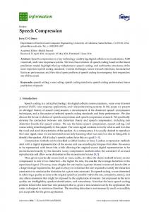
4.1 Description of the test field Opis probnog polja The concept of the analysis is generally considered to be complete if the results of the tests confirm assumptions derived from the model and geophysical interpretation. Therefore, P refraction tomography of vibro gravel pile test field was carried out, Fig. 1 (KTC Krapina, October 2007). Pile field has to improve soil properties and to support foundations of the building. The test field consisted of 21 piles in a single line (edge row of the piles layout), at equidistant interspacing of 1,1 m. Each pile had a length of 7 m and a diameter of 0,8 m. According to the geotechnical investigation data and laboratory test results, a geotechnical model of soil in the test zone was made. The clayey sand (SC) layer was 8,0 m thick. The surface brown sand layer, had an average thickness ranging from 2,8-3,2 m, contained a clay component of low plasticity and very low consistency (Ic=0,22). The sub-layer of grey-brown sand had even organic admixtures and the consistency of the clay component was unexpectedly low (Ic=0,08). Groundwater table appeared at the depth of 1,5 m. Accepted geotechnical 3 parameters were: weight per unit volume γ= 19 kN/m , 2 internal friction angle ϕ= 31° and cohesion c = 5 kN/m . The number of SPT blows was mostly about 4-7 with frequent appearance of only one blow at depths ranging from 2,5-3,5 m.
4.2 Control of the gravel pile installation Kontrola ugradnje šljunčanih pilota The standard control of the gravel pile installation
Figure 1 The position of the test gravel pile profile and the position of the control profile in original soil Slika 1. Situacija s položajem probnog profila duž linije šljunčanih pilota i položaj kontrolnog profila za usporedbu Technical Gazette 18, 2(2011), 243-252
245
Estimation of vibro replacement by compression seismic waves
M. Gazdek, S. Strelec, M. Rezo
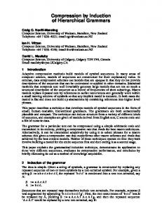
and compacting is carried out in real time and continuously during the whole process. Depending on the manufacturer of the equipment (Pennine or Keller for instance), the system pressure (P / MPa) or the vibroprobe power (I / A) can be monitored as a corresponding measure of the efficiency by depth (H / m) and by time (t / s) (P=P(H, t) or I=I(H, t)) [21]. The level of improvement cannot still be predicted with enough certainty because of site-specific characteristics of each particular location. The purpose of the testing pile field is thus on-site determination of vibrator operation regime. Actually, as the only improvement criterion, the executive operation mode has to be normalized to already confirmed empirical protocol [22], for example 1/4-2/4-1/4 rule of thumb, Fig. 2. These ratios refer to the level of pressure or power distribution related to gravel column length. In the first (bottom) quarter of the withdrawn cycle (i.e. 20-25 % of the pile length), the initially high power decreases exponentially. Then, in the middle section (approximately 50 % of the length) the level becomes stable, decreasingly slowly until the surface quarter (25-30 % of the length).
Figure 2 The expected t-P(I)-H diagram of vibrator protocol during gravel pile installation (dotted line). The relation P(I)-H is indirect arranged by time t, so that other curves show some possible outcomes with respect to the volume and compaction. Outcomes depend on the soil conditions and vibrator operation regime. Slika 2. Očekivani protokol vibratora tijekom ugradnje šljunčanih pilota u dijagramu t-P(I)-H (crtkana krivulja). Odnos P(I)-H je posredan po vremenu t pa ostale krivulje protokola prikazuju neke moguće ishode ugradnje obzirom na volumen i zbijenost. Ishodi ovise o uvjetima u tlu i o režimu rada vibratora.
In that section, there is a small increasing tendency of power, although the level from the first is generally not reached. For the control re-analysis of gravel installation, Pennine vibrator protocols (vibrograms) for two control groups (6-7-8 and 13-14-15, Fig. 1) of adjacent piles were chosen, Figure 3 and Figure 4. Fig. 5 and Fig. 6 depict interrelations between piles in a particular group. Consideration of the selected vibrograms was motivated by the fact that distribution of pressure by depth and time of adjacent piles differs considerably. Within the group and among groups also, there are significant differences in the total protocol time. Therefore, alterations of the pressure cannot be directly visually compared. It is evident that the installation time of a particular pile within the group differs by even more than 4 minutes. According to the operative protocol for installation 0,51 m of gravel column in 2 minutes at the most, this discrepancy can indicate pile volume enlargement by 14-28 %. 246
Figure 3 Installation Pennine protocols or vibrograms for pile group 6-7-8. Parameters Hmax, Pmax, Pave, Af and tf refer to the maximum depth, maximum and average pressure, total power and installation time. Changes of the regime are visible in depths of about 5 m and 22,5 m which mostly coincides with the 1/4-2/4-1/4 regime. Vibrograms for piles 6 and 7 show large variations at the depth of 2,5 m. A relatively slow increase of the average pressure with a considerable reduction of power may indicate a positive local and lateral effect on material compacting. Inversion was noticed with pile 7. Slika 3. Protokoli ugradnje ili Pennine vibrogrami za pilote 6-7-8. Parametri Hmax, Pmax, Pave, Af i tf se odnose na maksimalnu dubinu, maksimalno i srednje opterećenje, ukupnu snagu i vrijeme ugradnje. Promjene režima su vidljive na dubinama oko 5 m i 2÷2,5 m što se uglavnom poklapa s režimom 1/4-2/4-1/4. Vibrogrami za pilote 6 i 7 pokazuju značajne varijacije na dubini 2,5 m. Relativno blagi porast prosječnog opterećenja uz znatno smanjenje snage može ukazivati na lokalno i lateralno povoljan utjecaj na zbijenost. Inverzija je primijećena uz pilot 7.
The large installation time increments in a particular group can also reflect the increase of the total power used. Although power levels of the 6-7-8 pile group are mutually comparable, differences of adjacent columns are allocated in approximately doubled time. Yet, the increase of used power follows the increase of the average vibrator pressure and the installation time. Consequently, it can be supposed that the soil stiffness Tehnički vjesnik 18, 2(2011), 243-252
M. Gazdek, S. Strelec, M. Rezo
Procjena poboljšanja tla kompresijskim seizmičkim valovima
Figure 5 The pile group 6-7-8 vibrogram comparison with respect to their total embedding time tf. Except in the surface zone, the recordings are similar, so that the results can be analyzed relatively according to the time embedding, i.e. the best results can be expected in the zone of pile 8 that was embedded most quickly. Slika 5. Usporedba vibrograma grupe pilota 6-7-8 obzirom na njihovo ukupno vrijeme ugradnje tf. Osim u površinskoj zoni, zapisi su slični pa se rezultati mogu promatrati relativno prema vremenu ugradnje, odnosno najbolji se rezultati mogu očekivati u zoni pilota 8 koji se najbrže ugradio.
Figure 4 Installation Pennine protocols or vibrograms for pile group 13-14-15. Parameters Hmax, Pmax, Pave, Af and tf refer to the maximum depth, maximum and average pressure, total power and installation time. Changes of the regime at the depth of 5 m are expected, just as for piles 6-7-8, but for piles 13-14 that change is evident even by 1 m deeper. For these, the area at the depths of 3-4 m is also interesting, at which embedding of gravel lasted considerably longer, approximately 10 minutes for 2 m of the pile. A small increase of the average vibrator pressure with a considerable power reduction may indicate a locally positive effect on compaction. Slika 4. Protokoli ugradnje ili Pennine vibrogrami za pilote 13-14-15. Parametri Hmax, Pmax, Pave, Af i tf se odnose na maksimalnu dubinu, maksimalno i srednje opterećenje, ukupnu snagu i vrijeme ugradnje. Promjene režima na dubini 5 m su očekivane kao i za pilote 6-7-8, ali je za pilote 13-14 ta promjena vidljiva i do 1 m dublje. Za njih je zanimljivo i područje na dubinama 3÷4 m u kojem je ugradnja šljunka trajala značajno dulje, približno 10 minuta za 2 m duljine pilota. Mali porast prosječnog opterećenja vibratora uz osjetno smanjenje snage može ukazivati na lokalno povoljan utjecaj na zbijenost.
under both groups increases in the same direction. A larger time increments of the 6-7-8 group may also indicate a greater depth for the plane of considerable stiffness. By critical examination and evaluation of the vibrator operation regime, i.e. by comparing recommendations and the actual vibrogram, Figures 5 and 6, the rule 1/4-2/4-1/4 can also be perceived here. In such protocol the regime of Technical Gazette 18, 2(2011), 243-252
Figure 6 The pile group 13-14-15 vibrogram comparison with respect to their total embedding time tf. Except in the lower zone, the recordings are quite scattered. Since the times of embedding are different too, a quality estimation of the realized embedding is hardly possible. The middle zone is indicative, particularly of pile 13, so that embedding of a larger volume of gravel can be assumed. Slika 6. Usporedba vibrograma grupe pilota 13-14-15 obzirom na njihovo ukupno vrijeme ugradnje tf. Osim u donjoj zoni zapisi su prilično rasipani. Obzirom da su i vremena ugradnje različita, teško je moguća i kvalitativna procjena ostvarene ugradnje. Indikativna je srednja zona, posebno pilota 13, pa se može pretpostaviti ugradnja većeg volumena šljunka u tom dijelu.
the vibrator changes approximately after the first and third quarter, and therefore this predefined procedure should result in a P=P(H, t) site-specific relation for each particular pile. Still, a direct comparison of vibrograms is neither adequate nor justified, because the time scale may differ drastically even for the neighbor piles. That confirms again the fact that the installation protocol is heuristic and the results are very specific. Yet, if the P(H, t) distribution is known, the vibrogram will refer mostly to the gravel column. Since the differences of mechanical properties of the soil that is being improved can considerably change the vibrogram locus, the limit pressure criterion and protocol diagrams themselves are not sufficient for a final estimation of soil improvement.
247
Estimation of vibro replacement by compression seismic waves
M. Gazdek, S. Strelec, M. Rezo
Figure 7 Tomographic cross-section of compression wave velocity VP along the control profile P1'-1'. Under the control pile group 6-7-8, the boundary of 1500 m/s is steeper in relation to group 13-14-15. The seismic interpretation is the result of the WET method (Wavepath Eikonal Traveltime tomography, Rayfract 2.63, Intelligent Resources). Slika 7. Tomografski prikaz brzine VP kompresijskih valova duž kontrolnog profila P1'-1'. Ispod kontrolne grupe pilota 6-7-8 granica brzine 1500 m/s je strmija u odnosu na grupu 13-14-15. Presjek je rezultat seizmičke interpretacije WET metodom (Wavepath Eikonal Traveltime tomography, Rayfract 2.63, Intelligent Resources).
4.3 Refraction tomography profiles and interpretation Profili refrakcijske tomografije i interpretacija As major changes of the volume and compaction of the installed material are expected, the changes of the density and elastic moduli before and after column installation must be sufficiently distinctive for P-waves profiling. The average density of the clayey sand layer and the 3 compacted gravel column in the test field was 1940 kg/m 3 and 2160 kg/m respectively. The density change of this composite seismic medium of no more than 5 % could be expected. A very small velocity correction of about 2 % means that the rest of the velocity variation is affected by mechanical property changes in seismic profile. This fact is relevant for determining the influence of M module change on the P wave velocity variations. The assumption that pile-soil interaction should be resolved in the analysis of the mechanical property changes, before and after pile installation, was evidently encouraging. With that goal, P-wave seismic refraction was carried out along the control (original soil) profile 1'-1' and along pile test profile 1-1, Fig. 7 and Fig. 8. Thirty meters long parallel profiles were situated 1,5 m apart. Along each profile, array of 12 geophones was set at a regular interval of 2 m. Standard 10 Hz P-geophones (SM4, IO Sensor) for shallow refraction were used. Vertical low frequency seismic pulses were generated by a 10 kg hammer at 7 positions. The sample rate of 0,1 ms proved satisfactory for the first break picking (Abem Terraloc Mk3). For additional comparison, an array of 12 S-geophones with same technical specifications was also set in exactly the same way along the test S1-1 profile, Fig. 9. Consequently, simultaneous recording of the P and S waves from the same source was possible. A shear S-wave was actually a SV polarized S-wave. The velocity analysis of SV-waves is a part of the standard protocol in Cross-Hole tomography [23], because they have larger amplitudes and higher frequencies. It is also easier to generate them on the surface. Theoretically, there is no difference in the size of 248
these body wave velocities, but the field measurements can show significant differences, particularly due to anisotropic state of stress [24]. All seismic profiles were interpreted by standard Rayfract 2.63 (Intelligent Resources Inc.) WET method (Wavepath Eikonal Traveltime tomography), considering known advantages and shortcomings of such interpretations [25, 26]. Figures 7, 8 and 9 depict seismic tomographic cross-sections of P1'-1', P1-1 and S1-1 profiles. Since sub-horizontal layers in the original soil were expected, the lines of improvement on the P1-1 profile are evident and the tendency of mechanical property changes was emphasized. That fact was also confirmed by the control profile P1'-1' on which two important velocity zones can be distinguished (500 m/s and 1500 m/s). The boundary of the surface zone is sub-horizontal in the left part of the profile at the depth of 2 m, while smoothly descends to 3 m in the right part, Fig. 7. That boundary also corresponds to the groundwater level (during column installation the surface was up-leveled by 0,5-1,0 m). The effect of water saturation on the P-wave velocities was not observed in clayey sand. Consequently, it could still be considered that P velocity depends on the density and mechanical property changes, so it could also be expected that gravel columns will be visible in range of 1400-1700 m/s. The waviness of shallow boundary may as well indicate the presence or influence of piles on original soil (particularly visible for both 6-7-8 and 13-14-15 control pile group). Zones and trends of improvement on the S1-1 profile are also distinctive, but with considerably smooth contours (they are partially offset in relation to the P1-1 profile). Changes are observed at depth ranging from 3,5 m to 5,5 m in control pile zones (groups 6-7-8 and 13-14-15) and somewhat deeper in the central part of the cross-section. The seismic cross-section P1'-1' of the original soil was also used for the sensitivity control of the P-wave velocity field from the pile testing profile P1-1. Changes of the velocity can be structured by direct comparison of the VP velocity field from the P1-1 and P1'-1' cross-sections, Figure 10. The condition is that dimensions of interpreted velocity fields Tehnički vjesnik 18, 2(2011), 243-252
M. Gazdek, S. Strelec, M. Rezo
Procjena poboljšanja tla kompresijskim seizmičkim valovima
Figure 8 Tomographic cross-section of compression wave velocity VP along the test gravel pile profile P1-1. Lines of velocity increase (improvement lines) follow the shape of the boundary of 1500 m/s. The seismic interpretation is the result of the WET method (Wavepath Eikonal Traveltime tomography, Rayfract 2.63, Intelligent Resources). Slika 8. Tomografski prikaz brzine VP kompresijskih valova duž probnog profila P1-1. Pravci porasta brzine (poboljšanja) slijede oblik granice 1500 m/s. Presjek je rezultat seizmičke interpretacije WET metodom (Wavepath Eikonal Traveltime tomography, Rayfract 2.63, Intelligent Resources).
Figure 9 Tomographic cross-section of shear S-wave velocity along the test gravel pile profile S1-1. Lines of P-waves velocity increase were transposed from the P profile. The contours of VS changes are smooth and seldom so that, due to the tendency of lateral velocity layering, lines of improvement are partially shifted. The seismic interpretation is the result of the WET method (Wavepath Eikonal Traveltime tomography, Rayfract 2.63, Intelligent Resources). Slika 9. Tomografski prikaz brzine VS posmičnih S valova duž probnog profila S1-1. Pravci porasta brzine P valova su preneseni s profila brzina P valova. Konture promjena VS su blaže i rjeđe, pa su pravci poboljšanja zbog tendencije lateralnog uslojavanja brzina, djelomično pomaknuti. Presjek je rezultat seizmičke interpretacije WET metodom (Wavepath Eikonal Traveltime tomography, Rayfract 2.63, Intelligent Resources).
are the same. The legend shows velocity ratio VP(P1-1) / VP(P1'-1'). The presentation of the Poisson's ratio of the pile test profile is interesting, since the P and S velocities have been determined. Direct determination of the Poisson's ratio values according to the theory of elasticity is justified only if both P and S velocity values refer to the same volume section of the seismic media. Therefore, it was expected that the range of the coefficient values could be wider than the interval (0;0,5), because the transfer paths of the compression and shear disturbance in the geomedium are not generated in the same way. However, the goal of such presentation is to confirm the shapes, zones and positions of mechanical property variations, and not to unconditionally determine their Technical Gazette 18, 2(2011), 243-252
(absolute) values. By careful consideration of the presented values reliability, the mean value of all elements of the Poisson's ratio matrix was determined at 0,347. The meaning of that presentation concept becomes clear when only positions of values from the (0;0,5) interval, mean value of 0,179, are shown on the P-wave velocity ratio cross-section, Fig. 11. The zones of significant variations overlap with the changes of the P-wave velocities exceptionally well.
249
Estimation of vibro replacement by compression seismic waves
M. Gazdek, S. Strelec, M. Rezo
Figure 10 Contour presentation of the interpreted P-wave velocity ratio of test and control profile VP (P1-1/P1'-1'). This field of values presents velocity ratios of reference cells from tomographic cross-section (processed in the Wolfram Mathematica 5.0).The positions and the contours form coincide with the P1-1 tomographic cross-section very well. Slika 10. Konturni prikaz omjera interpretiranih brzina P valova duž probnog i kontrolnog profila VP (P1-1/P1'-1'). Polje vrijednosti je omjer brzina referentnih ćelija tomografskog presjeka obrađenog u programu Wolfram Mathematica 5.0. Položaj i oblik kontura se vrlo dobro slažu s tomografskim presjekom P1-1.
Figure 11 Variations of the test field Poisson's ratioo ν (white contours) presented in the matrix of the P-wave velocities ratio (processed in the Wolfram Mathematica 5.0). Positions and forms of contours coincide very well with improvement zones determined by P-wave refraction tomography. Slika 11. Promjene Poissonovog omjer ν probnog polja (bijele konture) prikazane na matrici omjera brzina P valova (obrađeno u programu Wolfram Mathematica 5.0). Pozicije i oblici kontura se vrlo dobro poklapaju sa zonama poboljšanja utvrđenih na temelju usporedbe brzina P valova.
5 Conclusion Zaključak The control of vibro gravel columns by analysis of compression or P-wave velocity variations proved to be successful and justified. The relative relation of the condition before and after the pile field installation can be well determined by the position. The best confirmation of this concept is seen in the velocity ratio distribution of the test and control profile by depth. The values of the velocity ratios matrix are arranged as the vector by depth, so that the effect of improvement along the whole test field could be concisely determined, Fig. 12. The shape of the ratio variations coincides well with the vibrator operation protocol.
250
However, the changes of the P-wave velocity ratio by the length of the piles can be clearly quantified. The level and the range of improvement under piles can also be ascertained (the maximum value of the ratio is recorded at the depth of 8-8,5 m). A square of the P-wave velocity ratio shows that the ratio of elastic constant or the modulus of the compression wave can be accepted as a measure of soil improvement by vibro replacement.
Tehnički vjesnik 18, 2(2011), 243-252
M. Gazdek, S. Strelec, M. Rezo
Figure 12 The distribution of the P-wave velocity ratio VP (P1-1/ P1'-1') by depth. Slika 12. Raspodjela omjera brzina P valova VP (P1-1/ P1'-1') po dubini.
6 References Literatura [1] Keller Ground Engineering. Overview of deep vibro techniques. http://www.kellergrundbau.com/download/pdf/en/Keller_10 -02E.pdf. (29.5.2010.) [2] Foundation Construction Group, Dubai, UAE. Soil Improvement by Vibro-Replacement. ETA-DEWA Substations Al Jadaf, Al Wasal and Consulate, Dubai, UAE. http://www.fcg-group.com/ETA_DEWA.pdf. (2.6.2010.) [3] Foundation Construction Group, Dubai, UAE. Soil Improvement by Vibro-Replacement. BOPP Factory Line-2, Gulf Packaging Industries, LTD. http://www.fcggroup.com/BOPP_Factory.pdf. (2.6.2010.) [4] Priebe, H. J. Vibro Replacement to Prevent Earthquake Induced Liquefaction. //Proceedings of the GeotechniqueColloquium at Darmstadt, Germany, (1998).http://kellerfondazioni.com/technical_paper_en/12_57E.pdf. (2.6.2010.) [5] Rodríguez, J. M. Vibro-techniques for Ground Improvement. VIth Argentine Congress of Port Engineering, (2010). http://www.aadipcongresos.com.ar/pdf/paper/dia7/36.Rodri guez, Juan Manuel/Rodriguez_et.al_AADIP2010.pdf. (4.6.2010.) [6] Hwang, J. H.; Tu, T. Y. Ground vibration during gravel pile construction. // Journal of Marine Science and Technology, 10(2002), 36-46. [7] Kirsch, F. Vibro Stone Column Installation and its Effect on Ground Improvement. http://www.gudconsult.de/bilder/00060_d.pdf. (2.6.2010.) [8] Szavits-Nossan, V.; Kovačević, M. S.; Szavits-Nossan, A. Posmična krutost i deformacija tla. Novi pogledi. // Građevinar, 51, 12(1999), 73-79.
Technical Gazette 18, 2(2011), 243-252
Procjena poboljšanja tla kompresijskim seizmičkim valovima
[9] Gotić, R.; Kovačević, M. S.; Jurić-Kačunić, D. Poslovni centar "Zagreb Tower" - Poboljšanje tla (Business centre "Zagreb Tower" - Soil improvement) // Priopćenja 4. savjetovanja HGD-a, Ojačanje tla i stijena, Opatija, 2006., 375-380. [10] Ley, R.; Adolfs, W.; Bridle, R.; Al-Homaili, M.; Vesnaver, A; Ras, P. Ground viscosity and stiffness measurements for near surface seismic velocity. // Geophysical Prospecting, 54, 6(2006), 751-762. [11] Menzies, B. Near-surface site characterization by ground stiffness profiling using surface wave geophysics. http://www.gdsinstruments.com/support/pdf/India Paper.pdf. (29.5.2010.) [12] Robinson, B.; Webster, S.; Alvarez, C. Stress Wave Methods in Civil Engineering. http://www.pile.com/Reference/5HighwayNDEConference/ StressWaveMethods.pdf. (29.5.2010.) [13] Mavko, G.; Mukerji, T.; Dvorkin, J. The rock physics handbook: tools for seismic analysis in porous media. Cambridge University Press, 1998., 2003. [14] Pullammanappallil, S.; Honjas, W.; Louie, J. N. Determination of 1-D shear velocities using refraction microtremor method. http://www.optimsoftware.com/white_papers/images/satish. pdf. (29.5.2010.) [15] Eurocode 7: Geotechnical Design - Part 1: General Rules. (ENV 1997-1:1994). [16] Sêco e Pinto, P. C. New developments in design methods of pile foundation. National Lab. of Civil Engineering (LNEC) & University of Combria. http://www.sochige.cl/material/I.Nuevos Desarrollos en diseno de cimentacione. Casos reales June2006.pdf. (29.5.2010.) [17] Szavits-Nossan, A.; Kovačević, M. S. Krutost tla pri malim deformacijama i njen značaj za temeljenje. // Priopćenja 2. savjetovanja HDMTT, Geotehnički problemi u urbanim sredinama, Varaždin/ (ur. R. Mavar), Hrvatsko društvo za mehaniku tla i temeljenje Zagreb, 1995., 407-418. [18] Robinson, B. R. Models for Prediction of Surface Vibrations from Pile Driving. Master of Science Thesis, North Caroline State University, Raleigh, North Caroline, 2006. [19] Rosyidi, S.A.; Nayan, K.A.M.; Taha, M. R.; Ismail, A. Estimating G-Max & Field CBR of Soil Subgrade Using a Seismic Method. // NDT.net, 11, 6(2006)(June). [20] Thasnanipan, N.; Maung, A. W.; Navaneethan, T.; Aye, K. Non-destructive integrity testing on piles founded in Bangkok subsoil. //Application of Stress-Wave Theory to Piles/ Niyama & Beim (eds) Balkema, Rotterdam, 2000., 171-177. [21] Yourman, A. M.; Rashidi, H. K.; Diaz, C. M.; Owaidat, L. M. Quality Control of Stone Columns in Variable Soils. http://www.magnuspacific.com/publications/QualityControl OfStoneColumnsInVariableSoils.pdf. (2.6.2010.) [22] VGNL Ltd. Nigeria, Vibroflotation Group (VG)-Solentache Bachy, France. Ground Improvement by Stone Column Methods. http://vibroflotation-ng.com/VGNL Profile.pdf. (2.6.2010.) [23] US Army Corps of Engineers. Geophysical Exploration for Engineering and Environmental Investigations. Manual EM 1110-1-1802. http://140.194.76.129/publications/engmanuals/ (2.6.2010.) [24] Redpath, B. B.; Edwards, R. B.; Hale, R. J.; Kintzer, F. C. Development of Field Techniques to Measure Damping Values for Near-surface Rocks and Soils. Unpublished report prepared for the National Science Foundation Earthquake Hazards Mitigation, New York (1982) (ref. in [23]). [25] Whiteley, R. J. Shallow Seismic Refraction Interpretation with Visual Interactive Ray Trace (VIRT) Modeling. // Exploration Geophysics, 35, (2004), 166-123. [26] Whiteley, R. J.; Eccleston, P. J. Comparison of shallow seismic refraction methods for regolith mapping. // Presented at the 18th ASEG Geophysical Conference & Exhibition (AESC2006). http://rayfract.com/papers/eg374whiteleyeditcheck.pdf (2.6.2010.) 251
Estimation of vibro replacement by compression seismic waves
M. Gazdek, S. Strelec, M. Rezo
Authors' address Adrese autora Mario Gazdek, Dr. sc. Sveučilište u Zagrebu, Geotehnički fakultet University of Zagreb, Faculty of Geotechnical Engineering Hallerova aleja 7, Varaždin, Croatia Contact: Tel 042 408 900/Fax 042 313 587
[email protected] Stjepan Strelec, Dr. sc. Sveučilište u Zagrebu, Geotehnički fakultet University of Zagreb, Faculty of Geotechnical Engineering Hallerova aleja 7, Varaždin, Croatia Contact: Tel 042 408 900/Fax 042 313 587
[email protected] Milan Rezo, Dr. sc. Sveučilište u Zagrebu, Geodetski fakultet University of Zagreb, Faculty of Geodesy Kačićeva 26, Zagreb, Croatia Contact: Tel 01 4639 222/Fax 01 4828 081
[email protected]
252
Tehnički vjesnik 18, 2(2011), 243-252