Ethernet was the technological basis for the IEEE 802.3 specification, which was
initially released ... Together, Ethernet and IEEE 802.3 currently maintain the.
5
CHAPT ER
Ethernet/IEEE 802.3 Background Ethernet was developed by Xerox Corporation’s Palo Alto Research Center (PARC) in the 1970s. Ethernet was the technological basis for the IEEE 802.3 specification, which was initially released in 1980. Shortly thereafter, Digital Equipment Corporation, Intel Corporation, and Xerox Corporation jointly developed and released an Ethernet specification (Version 2.0) that is substantially compatible with IEEE 802.3. Together, Ethernet and IEEE 802.3 currently maintain the greatest market share of any local-area network (LAN) protocol. Today, the term Ethernet is often used to refer to all carrier sense multiple access/collision detection (CSMA/CD) LANs that generally conform to Ethernet specifications, including IEEE 802.3. When it was developed, Ethernet was designed to fill the middle ground between long-distance, low-speed networks and specialized, computer-room networks carrying data at high speeds for very limited distances. Ethernet is well suited to applications where a local communication medium must carry sporadic, occasionally heavy traffic at high peak data rates.
Ethernet/IEEE 802.3 Comparison Ethernet and IEEE 802.3 specify similar technologies. Both are CSMA/CD LANs. Stations on a CSMA/CD LAN can access the network at any time. Before sending data, CSMA/CD stations “listen” to the network to see if it is already in use. If it is, the station wishing to transmit waits. If the network is not in use, the station transmits. A collision occurs when two stations listen for network traffic, “hear” none, and transmit simultaneously. In this case, both transmissions are damaged, and the stations must retransmit at some later time. Backoff algorithms determine when the colliding stations retransmit. CSMA/CD stations can detect collisions, so they know when they must retransmit. Both Ethernet and IEEE 802.3 LANs are broadcast networks. In other words, all stations see all frames, regardless of whether they represent an intended destination. Each station must examine received frames to determine if the station is a destination. If so, the frame is passed to a higher protocol layer for appropriate processing. Differences between Ethernet and IEEE 802.3 LANs are subtle. Ethernet provides services corresponding to Layers 1 and 2 of the OSI reference model, while IEEE 802.3 specifies the physical layer (Layer 1) and the channel-access portion of the link layer (Layer 2), but does not define a logical link control protocol. Both Ethernet and IEEE 802.3 are implemented in hardware. Typically, the physical manifestation of these protocols is either an interface card in a host computer or circuitry on a primary circuit board within a host computer.
Ethernet/IEEE 802.3 5-1
Physical Connections
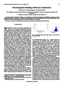
Physical Connections IEEE 802.3 specifies several different physical layers, whereas Ethernet defines only one. Each IEEE 802.3 physical layer protocol has a name that summarizes its characteristics. The coded components of an IEEE 802.3 physical-layer name are shown in Figure 5-1.
Figure 5-1
IEEE 802.3 Physical-Layer Name Components
LAN segment length, in 100-meter multiples
LAN speed, in Mbps
S1388a
“Base” = baseband “Broad” = broadband
10Base5
A summary of Ethernet Version 2 and IEEE 802.3 characteristics appears in Table 5-1.
Table 5-1
Ethernet Version 2 and IEEE 802.3 Physical Characteristics IEEE 802.3 Values Ethernet Value
10Base5
10Base2
1Base5
10BaseT
10Broad3 6
Data rate (Mbps)
10
10
10
1
10
10
Signaling method
Baseband
Baseband
Baseband
Baseband
Baseband
Broadband
Maximum segment length (m)
500
500
185
250
100 Unshielded twisted-pair wire
1800
Media
50-ohm coax (thick)
50-ohm coax (thick)
50-ohm coax (thin)
Unshielded twisted-pair wire
Unshielded twisted-pair wire
75-ohm coax
Topology
Bus
Bus
Bus
Star
Star
Bus
Characteristic
Ethernet is most similar to IEEE 802.3 10Base5. Both of these protocols specify a bus topology network with a connecting cable between the end stations and the actual network medium. In the case of Ethernet, that cable is called a transceiver cable. The transceiver cable connects to a transceiver device attached to the physical network medium. The IEEE 802.3 configuration is much the same, except that the connecting cable is referred to as an attachment unit interface (AUI), and the transceiver is called a medium attachment unit (MAU). In both cases, the connecting cable attaches to an interface board (or interface circuitry) within the end station.
5-2 Internetworking Technology Overview
Frame Formats
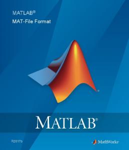
Frame Formats Ethernet and IEEE 802.3 frame formats are shown in Figure 5-2.
Figure 5-2
Ethernet and IEEE 802.3 Frame Formats Ethernet 7
1
S Preamble O Destination address F
Field length, in bytes
6
2
46-1500
4
Source address
Type
Data
FCS
6
IEEE 802.3 7
1
6
S Preamble O Destination F address
6
2
46-1500
4
Source address
Length
802.2 header and data
FCS
S1291a
Field length, in bytes
SOF = Start-of-frame delimiter FCS = Frame check sequence
Both Ethernet and IEEE 802.3 frames begin with an alternating pattern of ones and zeros called a preamble. The preamble tells receiving stations that a frame is coming. The byte before the destination address in both an Ethernet and a IEEE 802.3 frame is a start-of-frame (SOF) delimiter. This byte ends with two consecutive one bits, which serve to synchronize the frame reception portions of all stations on the LAN. Immediately following the preamble in both Ethernet and IEEE 802.3 LANs are the destination and source address fields. Both Ethernet and IEEE 802.3 addresses are 6 bytes long. Addresses are contained in hardware on the Ethernet and IEEE 802.3 interface cards. The first 3 bytes of the addresses are specified by the IEEE on a vendor-dependent basis, while the last 3 bytes are specified by the Ethernet or IEEE 802.3 vendor. The source address is always a unicast (single node) address, while the destination address may be unicast, multicast (group), or broadcast (all nodes). In Ethernet frames, the 2-byte field following the source address is a type field. This field specifies the upper-layer protocol to receive the data after Ethernet processing is complete. In IEEE 802.3 frames, the 2-byte field following the source address is a length field, which indicates the number of bytes of data that follow this field and precede the frame check sequence (FCS) field. Following the type/length field is the actual data contained in the frame. After physical-layer and link-layer processing is complete, this data will eventually be sent to an upper-layer protocol. In the case of Ethernet, the upper-layer protocol is identified in the type field. In the case of IEEE 802.3, the upper-layer protocol must be defined within the data portion of the frame, if at all. If data in the frame is insufficient to fill the frame to its minimum 64-byte size, padding bytes are inserted to ensure at least a 64-byte frame. After the data field is a 4-byte FCS field containing a cyclic redundancy check (CRC) value. The CRC is created by the sending device and recalculated by the receiving device to check for damage that might have occurred to the frame in transit.
Ethernet/IEEE 802.3 5-3
Frame Formats
5-4 Internetworking Technology Overview


![[MS-ONE]: OneNote File Format](https://m.moam.info/img/260x300/ms-one-onenote-file-format_6479e079097c4769028bd88d.jpg)