Freek Stulp, Suat Gedikli, and Michael Beetz. Informatik IX .... cided to reuse the manual calibration methods, instead of automatic calibration methods .... Since the shutter speed of our cameras is 1/120s, the maximum distance a robot can ...
Evaluating Multi-Agent Robotic Systems Using Ground Truth Freek Stulp, Suat Gedikli, and Michael Beetz Informatik IX, Technische Universit¨ at M¨ unchen D-85748 Garching bei M¨ unchen, Germany {stulp|gedikli|beetz}@in.tum.de
Abstract. A thorough empirical evaluation of multi-agent robotic systems is greatly facilitated if the true state of the world over time can be obtained. The accuracy of the beliefs as well as the overall performance can then be measured objectively and efficiently. In this paper we present a system for determining the ground truth state of the world, similar to the ceiling cameras used in RoboCup small-size league. We have used this ground truth data to evaluate the accuracy of the selfand object-localization of the robots in our RoboCup mid-size league team, the AGILO RoboCuppers. More complex models of the state estimation module have also been learned. These models provide insight into the workings and shortcomings of this module, and can be used to improve it.
1
Introduction
Evaluating dynamic robotic multi-agent systems is difficult for several reasons. Since these systems are dynamic, it is difficult to capture the state of the world at a certain time or at certain time intervals without interfering with the course of events. How to accurately measure the position of a robot, if it is traveling at 2m/s? Robotic platforms usually suffer from noisy sensors and hidden state. A robot’s beliefs about the world are therefore incomplete, uncertain and inaccurate. How to determine where a robot really was, if you only have its belief state to judge by? Multi-agent systems also require that several subsystems are evaluated at the same time, as well as the interactions between them. We have implemented a system that can automatically provide ground truth about the state of the world in dynamic robotic multi-agent systems such as RoboCup teams. This information is stored in log-files, alongside the perceived state of the world of each robot. This system is very similar to the global view cameras use in the RoboCup small-sized league. It consists of one or more cameras mounted above the field looking downward. Each robot has a distinctive top-marker that is easy to detect by these cameras. Since the cameras are static, and can locate the markers precisely, this yields very accurate data on the location and orientation of each robot on the field. We have found many uses for this ground truth data. Empirically evaluating the performance of self-localization or other local state estimation algorithms
is possible, and we have also learned more complex models of the sensors and state estimation algorithms. These models can greatly help to understand, and improve the system. In the remainder of this paper we proceed as follows. The next section describes the hardware of ground truth system, and the image processing used to acquire accurate information on the poses of robots. In Section 3 we describe how we use this information to evaluate and model our RoboCup team, the AGILO RoboCuppers. Section 4 concludes with a summary and prospectives for future research.
2
Acquiring ground truth
In this section we will briefly present the hardware and image processing used to obtain the ground truth state of the world. This state consists of the location and orientation of each robot, as well as the location of the ball. There are several ways to locate robots, for instance based on ultrasound, such as Active Bat [13], or the Cricket Location Support System [9], or based on Radio Frequency signal strengths of packets on an wireless network [7]. The resolution of these methods are 9cm, 1.2m and 1.5m respectively. The first one is too expensive, and the latter two are too inaccurate. We have chosen a vision-based method which is similar to the global vision system used in the small-size league of RoboCup [4]. It is combines high accuracy with low cost. 2.1
Hardware
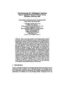
Our ground truth system consists of two cameras with an opening angle of 90◦ , at a height of approximately 3m above the field. The cameras are facing downward, and together they cover the whole training field, which is 6.4m x 10.4m. The system is easily extendible to more cameras. For our training field we will install a third camera for accuracy, and a standard 10m x 14m RoboCup field will need four. The maximum number of cameras that can be used is mainly limited by the free PCI-Slots for the frame-grabbers. The computational power of the used computer, and the bandwidth of the PCI-BUS do not physically limit the number of cameras, but do influence the frame-rate at which ground truth can be computed. The cameras have a resolution of 384 x 288 Pixels and are connected with 10m (S-Video Y/C) cables to the frame-grabbers. Using high quality cables with less resistance and good shielding would also work for longer distances. For a standard RoboCup field, the 10m cables are sufficient. The robots can be distinguished from one another using color markers, exactly as in done in the RoboCup small-size league [4]. The markers we use are shown in Figure 1. The largest circle, which we will refer to as the main-circle, indicates to which team the robot belongs (cyan/magenta). The two smaller yellow or blue circles, which we will refer to as the sub-circles, are a binary encoding of the player’s number. The first image in Figure 2 shows two robots
with top markers representing #1 and #3. This binary encoding only allows for four (22 ) distinct markers per team, as shown in figure 1. Recent rule changes in RoboCup mid-size league allow for more than four players. By adding a small circle, or adding a color we could have eight (23 ) or nine (32 ) distinct markers, respectively. The marker is essentially an abstraction of the robot’s pose. The marker has been specifically designed for perception with a color camera, so that it can be detected well, and localized accurately. It is not our goal to capture other aspects of the robot’s state (kickers, grippers, arms), this abstraction therefore suffices. Also, the methods described in this paper assume that the marker is parallel to the floor. For legged robots, this assumption might not always hold.
Fig. 1. The top markers
2.2
Calibration and camera localization
The ceiling cameras were formerly used on our robots. Therefore, all the algorithms for camera and color calibration on the robots can simply be applied in the new configuration as well. For practical reasons, we have therefore decided to reuse the manual calibration methods, instead of automatic calibration methods proposed in RoboCup small-size league [5, 12]. Camera localization is automated, using the localization methods previously employed on the robots. Calibrating the internal camera parameters is done using a commercial software package. Some images of a calibration plate in different positions and angles are taken. The software package then deals with the camera parameter optimization. The entire procedure takes about 10 minutes per camera. For color calibration, we grab images and manually map image regions to given color classes. The software then generalizes over these color samples, which cover about 10 to 20% of all colors in the 16 bit color-space, so that each possible color in the color-space can be mapped to a given color class. This is stored in a look-up table for each camera. This procedure takes about 10 to 15 minutes per camera. The cameras localize themselves using the same algorithms used on our robots [1]. The only difference is that the robots assume that the camera has only three degrees of freedom, as the actual six degrees are computationally too expensive. Since the ceiling cameras only have to localize themselves once, and
accuracy is more important, we use the full six degrees. Since localization is automated, this procedure only takes a few minutes. Once the cameras are in place on the ceiling, or attached to some scaffolding, the entire calibration and localization procedure will take less than thirty minutes per camera. Four cameras will therefore take two hours. Because the cameras can be calibrated in parallel, four people could manage it in thirty minutes. On our field, all cameras can use the same look-up table generated by color calibration. This step therefore only has to be executed once. This might not be the case for fields that are inhomogeneously lit, or cameras that are not so similar to one another. 2.3
Image processing software
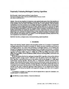
Each camera grabs images at a rate of 15Hz. The first image in Figure 2 shows an example of such an image. The images are then segmented by color using the look-up tables generated during color calibration.
Fig. 2. Intermediate steps in image processing.
In order to detect the markers, we first search for blobs corresponding to the colored circles on the markers. For each blob, the center is computed. Then we have to determine if a blob represents a circle on a marker or not. As the sizes of the main-circles and sub-circles are known, we can filter out blobs not belonging to a marker by size and compactness. To take into account that the shape and size of a blob will vary with the position of the marker on the field, the measures of compactness and size are position dependent. To compute appropriate thresholds, the center of each blob is projected on a plane parallel to the floor at the height of the robots. This projection is used to determine the expected shape and size of this blob. Only blobs that have the right size and shape, within a certain margin of error, are accepted as belonging to a marker. For the partially overlapping area of two cameras, we use the average of two
blobs of the same color, if they overlap more than 20%. This yields a set of magenta, cyan, blue, yellow and orange blobs, as can be seen in the second image of figure 2. The centers and color label of all these blobs are stored in a list for further computation. Each orange center is assumed to be a ball. Every magenta and cyan center in this array is assumed to be a main-circle. We then search all blue and yellow centers whose distance to the main-circle are in the range 14.5±5.0. The distance between two sub-circles must be within the range 18.0 ± 6.0. Only these configurations of blob centers are deemed to be a marker. With the center position of the main-circle we can determine the location of the marker, and with the direction of the two sub-circles the orientation of the marker. The color of the main-circle encodes the robot’s team, and the color of the sub-circles the robot’s number. Since each marker is unique, there is no data association problem between a robot and a detected marker. These results are communicated to and displayed in the program we use to monitor the state of the world, as can be seen in the last image. In this example, there are two robots, whose self-localization is displayed in blue. Their actual position, determined by the ground truth system, is displayed as a white line, the start of which indicates the robot’s center. The orange ball is where robot 3 beliefs the ball to be, and the ground truth position is displayed in red. This graphical display allows us to make quick on-line inferences: “Robot 3 is localized very well, and has localized the ball reasonably. Robot 1 is not localized that well, but good enough for performing useful behavior.” 2.4
Accuracy of ground truth estimates
Although we assume that the ground truth data represents the actual state of the world, it is of course an estimate. The question is if this estimate is accurate and certain enough to evaluate and model a robot, or a team of robots. These issues are discussed in this section. Theoretical accuracy: We determine the highest theoretical accuracy that can be achieved, based on the image resolution (384 x 288), the height of the camera (3m), the opening angle of the lens (90◦ ). For these values, one pixel in the image represents an area of approximately 1.22cm x 1.64cm at center of the image, up to 2.44cm x 3.25cm at the border of the image. Determining positions of pixels with higher resolution is insignificant. By using large color markers with a diameter between 15 and 20cm, the marker’s size in the image is 20 to 170 pixels. The center of each blob can be calculated more precisely than one pixel, so theoretically, the center of the circle can be determined more precisely. Accuracy for static objects: To determine the actual accuracy of robot localization by the ground truth system, we placed a robot with marker on fifteen different positions on the field. We measured the actual position by hand (ground ground truth, so to speak), and compared it to the pose estimated by the system. For the localization of the robots we have an accuracy of 0.3 to 5.2 cm and for its orientation 1 to 2.3◦ .
Accuracy for dynamic objects: As it is difficult to measure the location of moving robots by hand, we were not able to determine these values for moving robots. Since the shutter speed of our cameras is 1/120s, the maximum distance a robot can drive during an exposure is 1.7cm for a robot traveling at 2m/s. The maximum angle it can turn in 1/120 of a second is about 4◦ for a robot turning with 500◦ /s. These values are lower than the theoretical accuracy that can be obtained, so we do not expect blurring to influence the accuracy significantly. Also, since the image processing algorithms have no internal state, each image is processed completely independently of all previous images. Therefore errors are not propagated and accumulated. Since the cameras are not synchronized, there might be a delay between images taken by different cameras. This might be a problem, when two overlapping cameras detect the same robot at different times. Given that the frame-rate is 15Hz, the maximum distance a robot can drive between these two times is about 7cm, and the maximum angle a robot can turn is 19◦ . The estimated world state is not really a snapshot, but a time interval of the real world state. For the overlapping area recorded by two cameras, we reduce the temporal and spatial errors by averaging all blobs detected by both cameras, as described in Section 2.3. Robustness of marker detection: Apart from the accuracy, another important issue is whether a marker is detected at all. To evaluate this we have conducted three experiments. First of all, we placed eight markers on the field, and determined how often they were detected over 4100 frames, which is about 4.5 minutes. Some are detected 97-99% of the time, and others a full 100%. The average is 99.0%. The complete results are listed in Table 1, in the row labeled Static. In the second experiment we removed one of the eight markers from the field, and measured how often it was (falsely) detected over an interval of 6000 frames, which is more than 6.5 minutes. This was done for all eight markers. Most markers were correctly never detected. The results are listed in the second row of Table 1, labeled Removed. In the last experiment, we drove a robot across the field by remote control for 2000 frames, which is more than 2 minutes. This was repeated for each marker. The results were not as good as for the static experiment, but nevertheless detection rates are still 97.5% on average. Results are listed in the row labeled Dynamic.
Experiment #Frames 1) Static 2) Removed 3) Dynamic
4100 6000 2000
Magenta (%) Cyan (%) Mean (%) 1 2 3 4 1 2 3 4 100.0 99.2 100.0 97.7 100.0 99.7 98.0 97.1 99.0 0.0 0.0 0.0 0.0 0.1 0.5 0.0 0.4 0.2 99.0 96.7 98.8 96.2 98.8 98.2 96.4 96.1 97.5
Table 1. Results of marker detection robustness experiments
2.5
Logging the ground truth
As is customary in RoboCup mid-size league our robots communicate their state estimation results to a central computer. This data is used for monitoring the robots’ beliefs about the world on-line. Since the data is already available centrally in the monitoring program, it stores it in one log file. This is similar to the logging system of the Ulm Sparrows [6]. As discussed in section 2.3, the monitoring program also receives the data from the ground truth system. Therefore, it was a simple step to include the ground truth data into the log file. As the clocks of all robots and the ground truth system are synchronized, we have a distinct correspondence between the robots belief state and its actual pose given by the ground truth data. This enables a direct comparison, on- and off-line.
3
Evaluating and modeling the AGILO RoboCuppers
In this section we will discuss how we have used the ground truth system to evaluate and model our RoboCup mid-size team, the AGILO RoboCuppers. The data we acquire is not only used for determining quantitative measures of performance, but also to learn complex and qualitative models of the system’s competences and weaknesses. Since such models help to understand the system and to break down its complexity, it is also an important aspect of evaluating it. 3.1
Evaluating state estimation accuracy
Before we could acquire ground truth data to evaluate the accuracy of selflocalization, we measured it by hand for static positions, as described in section 2.4. Of course, this yields too few, and more annoyingly, unrealistic data. When the robots are performing their task self-localization is much more difficult, as they are constantly moving, and landmarks are occluded by teammates and opponents. The ground truth data allows us to measure the performance constantly over time, and under realistic conditions. In three friendly matches against the Ulm Sparrows [6] we were able to log approximately two hours of net playing time. Quantitative data for these experiments can be found in Table 2. The left, center and right column display the accuracies (Root-Mean-Square Error, or RMSE) and the standard deviation of the self-localization, of the ball observations and of the opponent observations of the individual robots. These results are taken from [1]. The localization worked very well for the goal-keeper (#1) and the striker (#4). Their localization accuracies are estimated to be 12 and 19 cm, respectively. This is not surprising for the goal-keeper, since it is quite stationary and can observe the penalty area lines well most of the time and use them for precise localization. The accuracy achieved by robot (#4) is quite remarkable since it traveled long distances across the field and scored several goals. The inferior
Self-Localization Ball Observations Opponent Observations Robot RMSE (m) std.dev. (m) RMSE (m) std.dev. (m) RMSE (m) std.dev. (m) 1. Match #1 0.12 0.07 0.31 0.23 0.38 0.26 #2 0.33 0.15 0.38 0.25 0.50 0.26 #3 0.24 0.11 0.24 0.22 0.46 0.26 #4 0.19 0.09 0.25 0.23 0.37 0.25 2. Match #1 0.11 0.06 0.33 0.22 0.42 0.26 #2 0.33 0.19 0.35 0.25 0.48 0.27 #3 0.21 0.10 0.28 0.24 0.40 0.24 #4 0.20 0.10 0.25 0.26 0.35 0.24 3. Match #1 0.12 0.09 0.27 0.22 0.40 0.26 #2 0.37 0.21 0.34 0.26 0.51 0.26 #3 0.23 0.11 0.26 0.22 0.44 0.25 #4 0.19 0.10 0.18 0.20 0.38 0.25 Mean of all matches #1 0.12 0.08 0.29 0.22 0.40 0.26 #2 0.34 0.18 0.36 0.25 0.50 0.26 #3 0.23 0.11 0.26 0.23 0.44 0.25 #4 0.19 0.10 0.21 0.22 0.37 0.25 Table 2. Evaluation of state estimation accuracy
accuracies of robot (#2) and robot (#3) led to further investigations and it was found, that both robots were using suboptimal camera parameterizations. Furthermore, robot (#2) was also using a suboptimal color lookup table, and as such failed to produce good classification results for a wide range of images. The addition of a suboptimal color classifier causes the localization algorithm to be unstable and fail more often by two orders of magnitude. This is a clear example of how the quantitative evaluation of the robotic system using the ground truth gives insight of the system’s performance, and can help in detecting errors. Table 2 also summarizes the input data used to test the opponent tracking algorithm. Self-localization errors and inaccuracies often cause errors in ball and opponent observations. As a rule of thumb, the errors for opponent observations are usually greater than the errors for ball observations. This is due to the unique circular shape of a ball. Arbitrary robot shapes hamper the opponent detection routines and as such add an indirect level of noise. The unfortunate influence of the wrong intrinsic camera parameters of robots (#2) and (#3) on the observations is clearly visible. In [8], Merke et al. also use a laser range finder as an external sensor to determine the actual position of a robot, and evaluate its self-localization. Unfortunately, the laser range finder cannot measure orientation, and the system
has not been designed to track multiple robots. Their main aim was to record the ground truth for a omni-vision benchmark. 3.2
Learning models of the system
More elaborate sensor models can also be learned using the ground truth data. Apart from determining the mean error, as discussed in section 3.1, interesting and more complex aspects are: Does the robot perceive objects that aren’t there (hallucinations)? Does the robot not perceive objects that are there (oversights)? Can it be predicted when these failures arise? Using the ground truth system, we can detect hallucinations and oversights automatically. If a robot’s state estimation detected an object at a certain position, but ground truth did not (within a 30cm radius), the robot has hallucinated this object. If the ground truth system detected an object, but the robot did not (again within 30cm radius), the robot has overseen this object. We have used Quinlan’s C4.5 decision tree learning algorithm to learn predictive rules as to whether or not to integrate an observation into state estimation considering the current situation [11]. The robot learned rules that an observation is likely to be informative if 1. the observed distance D is less than 3.76086 and the robot has not lost track of its position 2. the robot is not turning, the angle φ between the observation and the direction the camera is pointed to is less than 22.91◦ and D ≤ 5.42 3. the robot is turning, D ≤ 6.87, and φ ≤ 43.6 There is a wealth of information in such learned models. First of all, it gives us insight into the workings and performance of the system. Apparently, the robot has problems discerning objects at distances larger them 3.7 meters. This performance loss might be due to insufficient image resolution or camera height. We could change this, make more experiments with ground truth, and relearn the decision tree to see if the changes have led to improved performance. Second, it can be used to improve the state estimation itself. In state estimation it is often assumed that every observation provides the robot with additional information that can be used to improve the state estimate. In reality, however, this is often not true. Applying the learned rules above to filtering observations we could reduce the hallucinated observations by one third. Since these observation are not used for further processing, state estimation also becomes more efficient. This example show clearly that having a model of the system and its shortcomings can help to understand and improve it. Finally, in the future we will use the learned decision tree to improve our simulator. At the moment the simulator uses accurate learned models of the robot’s dynamics [3]. The “sensor model” is very crude however: each agent simply receives the exact locations of all the objects in its field of view. The learned rules could be used to improve this model, and generate hallucinations, or generate oversights by deleting certain objects. When and where to do this can be determined using the decision tree.
3.3
Providing robots with the global state
Having access to the global game state also allows a thorough evaluation of the action selection module, independent of the inaccuracies and uncertainties that arise from the state estimation performed locally on the robot. In our system, the first step in developing or adapting control routines is made in the MRose simulator [3]. This simulator has an accurate learned model of the robot dynamics, and can simulate multiple robots on one field in parallel, using the same controller the robots use in the real world. Even though this simulator has good models of the environment, the low-level routines do not map to the real controller perfectly. Testing of the controller on the real robot is necessary to fine-tune the low-level routines. Without ground truth, this is difficult, as the robot’s imperfect state estimation makes is difficult to see the effects of changes to the low-level controllers, because unexpected behavior might arise due to false self-localization. To make this process easier we have enabled functionality to provide the robots with the global state, as computed by the ground truth cameras. This is exactly the same as in RoboCup small-size league. Using this set-up, we can test the robots’ control routines, without depending on state estimation. Of course, the final step is always to test the routines on a real robot with local state estimation. Assuming perfect localization is a fallacy, and routines for dealing with uncertain localization must also be implemented and tested. The ground truth system provides us with an intermediate and useful development step between the simulator and the real robot with local state estimation.
4
Conclusion and future work
In this paper we have presented a system for acquiring and storing ground truth data for dynamical multi-robot systems, such as our RoboCup team. We have also discussed how this data can be used to evaluate the robot’s performance, and how plan to construct models of the sensors and state estimation algorithms. Our future research will aim at learning further and more elaborate models to understand and improve state estimation. Another exciting direction is learning models of the opponents using ground truth. Up till now, such research has been confined to the simulation league in RoboCup [10, 2]. This is probably due to the accuracy and completeness of the data. The similar data provided by the ground truth system will hopefully allow the acquisition of similarly expressive models. The ground truth system could also be used to assist the referee in RoboCup games. It can accurately measure when a ball is over the line, when a goal has been scored, or when a robot has been in a penalty area for too long. Collisions could be determined by projecting a model of the robots’ shape onto the field at the measured pose, and detect if they make contact.
Acknowledgements The work described in this paper was partially funded by the German Research Foundation (DFG) in the SPP-1125, “Cooperating Teams of Mobile Robots in Dynamic Environments”.
References 1. Michael Beetz, Thorsten Schmitt, Robert Hanek, Sebastian Buck, Freek Stulp, Derik Schr¨ oter, and Bernd Radig. The AGILO 2001 robot soccer team: Experiencebased learning and probabilistic reasoning in autonomous robot control. Autonomous Robots, special issue on Analysis and Experiments in Distributed MultiRobot Systems, 2004. 2. Michael Beetz, Thomas Stammeier, and Sven Flossmann. Motion and episode models for (simulated) football games: Acquisition, representation, and use. In Proceedings of the International Conference on Autonomous Agents and MultiAgent Systems (AAMAS04), 2004. 3. S. Buck, M. Beetz, and T. Schmitt. M-ROSE: A Multi Robot Simulation Environment for Learning Cooperative Behavior. In H. Asama, T. Arai, T. Fukuda, and T. Hasegawa, editors, Distributed Autonomous Robotic Systems, 5. Springer, 2002. 4. Laws of the robocup F180 league 2004. http://www.itee.uq.edu.au/˜wyeth/F180 5. Alexander Gloye, Anna Egorova, Mark Simon, Fabian Wiesel, and Ra´ ul Rojas. Plug & play: Fast automatic geometry and color calibration for tracking mobile robots. In RoboCup 2004 International Symposium, 2004. 6. Gerhard Kraetzschmar, Gerd Mayer, Hans Utz, and et al. The Ulm Sparrows 2003. RoboCup 2003 International Symposium Padua, 2003. 7. A. Ladd, K. Bekris, G. Marceau, A. Rudys, L. Kavraki, and D. Wallach. Roboticsbased location sensing using wireless ethernet. Technical Report TR02-393, Department of Computer Science, Rice University, 2002. 8. A. Merke, S. Welker, and M. Riedmiller. Line based robot localization under natural light conditions. In European Conference on Arificial Intelligence Machine Learning (ECAI) 2004, Workshop on Agents in real-time and dynamic environments, 2004. 9. Nissanka B. Priyantha, Anit Chakraborty, and Hari Balakrishnan. The Cricket location-support system. In Proceedings of the Sixth Annual ACM International Conference on Mobile Computing and Networking, pages 32–43. ACM Press, 2000. 10. Patrick Riley and Manuela Veloso. Recognizing probabilistic opponent movement models. In RoboCup-2001: Robot Soccer World Cup V, 2002. 11. T. Schmitt and M. Beetz. Designing probabilistic state estimators for autonomous robot control. In IEEE/RSJ Intl. Conf. on Intelligent Robots and Systems (IROS), 2003. 12. Chunmiao Wang, Hui Wang, William Y. C. Soh, and Han Wang. A real time vision system for robotic soccer. In Proc. 4th Asian Conference on Robotics and its Applications (ACRA2001), 2001. 13. A. Ward, A. Jones, and A. Hopper. A new location technique for the active office. IEEE Personnel Communications, 4(5):42–47, October 1997.