open API, has been defined in order to provide the desired functionality and support the model ..... sRO-csa-tr. . . IT-tr.
Evaluating Software Architecture in a Model-based Approach for Enterprise Information System Design Anargyros Tsadimas, Mara Nikolaidou, Dimosthenis Anagnostopoulos Department of Informatics & Telematics, Harokopio University of Athens 70 El. Venizelou Str, 176 71 Athens, Greece {tsadimas, mara, dimosthe}@hua.gr ABSTRACT Enterprise information system architecture design is the process of defining and optimizing its structure (both software and hardware) to effectively support provided functionality. System architects are combining software and hardware vital components, usually defined by other stakeholders, and are dealing with both functional and non functional requirements. Alternative architecture solution evaluation is usually a part of the design process, aiming to determine if the defined requirements are satisfied. A model-based approach, constituted of discrete views, each of which facilitates a discrete design task, has been proposed, while Systems Modeling Language (SysML) has been adopted for the model representation. In this paper, emphasis is given on the Evaluation View, aiming at the exploration of alternative software and hardware combination scenarios proposed in other views. The view facilitates the management of simulation experiments and results and the verification of predefined requirements. A case study, where the proposed model-based design approach has been applied is also discussed.
Categories and Subject Descriptors H.1 [Information Systems Applications]: Models and Principles; D.2.1 [Software Engineering]: Requirements/ Specifications
Keywords Enterprise Information Systems, Model-based Engineering, Architecture Design and Evaluation
1.
INTRODUCTION
Enterprise Information Systems (EIS) are large-scale, composite systems, consisting of software and hardware components, which should be defectively combined to ensure system efficient operation. EIS Architecture design consists of the definition and optimization of a system architecture comprised of software and hardware components, ensuring
Permission to make digital or hard copies of all or part of this work for personal or classroom use is granted without fee provided that copies are not made or distributed for profit or commercial advantage and that copies bear this notice and the full citation on the first page. To copy otherwise, to republish, to post on servers or to redistribute to lists, requires prior specific permission and/or a fee. SHARK ’10, May 2-8 2010, Cape Town, South Africa Copyright 2010 ACM 978-1-60558-967-1/10/05 ...$10.00.
that all software components are identified and properly allocated and that hardware components are properly combined to support the efficient operation of software components and provide the desired performance. It is usually performed by system architects and is characterized as a complex process [1]. It is evident that the identification of functional requirements, e.g. EIS components and their capabilities [2], are not enough to ensure EIS efficient operation. Non-functional requirements, e.g the conditions under which EIS components should operate [2], should also be taken into account. Visualization helps system architects to understand and utilize the architectural design decisions [10]. In practice, EIS Architecture design focuses on the efficient integration of EIS vital components already defined by other stakeholders than system architects [12]. There are a lot of EIS engineering methodologies in the literature [5]. A model-based approach for the design of EIS architecture is about elevating system models to a central and governing role in the design of the system. In such a case, design is to be accomplished by developing models of increasing detail ([5], [7]). In [12], the concept of conducting model-based EIS Architecture design was explored, based on a modular central model, consisting of discrete sub-views serving discrete design tasks. The proposed EIS Architecture Design model facilitates the description of both functional and non functional requirements and the design decisions related to them according to different perspectives often influenced by different EIS stakeholders. Each of the perspectives results to an independent sub-view serving a discrete design task. Non-functional requirements (NFRs) (for example performance requirements) play a significant role during EIS Architecture design [6], since they depict the conditions under which specific system components should operate, leading to alternative design decisions, thus they were grouped in a discrete view. EIS Architecture modelbased design was performed using Systems Modeling Language (SysML) [14] and a corresponding SysML profile was defined. Since EIS Architecture design is a complex process, proposed architecture scenarios should be evaluated [8] and properly adjusted, to achieve an acceptable solution. In the model-based approach proposed in [12], solution evaluation is treated as an independent activity, not integrated within the central model serving design tasks. Thus, the system designer is not supported by the central system model with information to make any EIS (software or hardware) redesign or requirement readjustment decisions. In this paper, we propose the extension of the EIS Architecture Design
model to incorporate EIS Architecture solution evaluations and perform requirement verification, as these tasks are often performed by the system designer to reach an acceptable design solution. Furthermore, solution evaluation results are part of the knowledge utilized by the designer to make redesign decisions. Thus, they be incorporated in the system design model and become available during EIS Architecture design process. An additional sub-view, called Evaluation View, which facilitates the definition of solution evaluation scenarios, the maintenance of evaluation results and the verification of requirements, is integrated in EIS Architecture design model to help the designer to make redesign or requirement readjustment decision if needed. The rest of the paper is organized as follows: Section 2 explains the main concepts of model-based EIS architecture design identifying basic tasks and corresponding views, focusing on system evaluation. In section 3 the corresponding model constituting EIS Architecture Evaluation view is analytically presented. In section 5 a case study, where the proposed model-based design approach has been applied focusing on the Evaluation View, is briefly discussed. Conclusions and future work reside in section 6.
2. 2.1
MODEL-BASED DESIGN OF EIS ARCHITECTURE EIS Architecture Design Tasks
According to [12], the basic tasks identified during any EIS design activity, are Requirement definition, Solution synthesis, Solution evaluation and Solution re-adjustment. Based on predefined requirements, the system designer build a solution on system synthesis. In order to decide if a solution is acceptable, evaluation is used. Until an accepted solution is reached, re-adjustments are performed. In the case of EIS architecture design, solution synthesis encompasses Functionality, Topology and Network Infrastructure definitions [12]. Functionality Definition focuses on software architecture design, Topology Definition on software allocation process and Network Infrastructure Definition on hardware architecture design. Non Functional Requirement (NFR) Definition should also be independently treated, since the conditions, under which the system should operate, play a significant role in design decisions. For each of these definitions, a corresponding EIS Architecture View has been defined. Furthermore, EIS Architecture Evaluation should be performed. In order to evaluate the designed solution, non functional requirements definition is used, focusing on system performance and availability requirements essential for EIS architecture design. Then, solution evaluation is performed and evaluation results are used to check whether non functional requirements are satisfied. If not, then EIS Architecture readjustment is performed until an acceptable EIS architecture synthesis is identified. To manage the evaluation process and maintain evaluation results a discrete EIS Architecture View is defined. EIS Architecture design tasks and corresponding views are presented in Figure 1. It is evident that all aforementioned tasks are interrelated, since non of them can be completed independently, while in most cases tasks are performed in parallel, and often repeatedly by the system architect in order to reach an EIS architecture satisfying both functional (identified during Func-
tionality Definition and partly during Topology and Network Infrastructure Definition) and non functional requirements (identified during NFR Definition). NFR Definition is performed in parallel with Functionality, Topology and Network Infrastructure Definition. Developing requirements and architectural artifacts in parallel has already been addressed in the literature [13]. After an EIS architecture has been defined, it should be evaluated, most commonly using simulation. Solution evaluation will determine whether the proposed solution is satisfying all functional and non functional requirements, or the system designer should improve the proposed architecture or readjust requirements by repeating definition tasks. Adopting a model-based approach for EIS Architecture design should provide the system architect with a common system model to support all design tasks and enable him/her to perform each design task in an independent fashion taking into account the restrictions imposed by other tasks. As defined in [12], the system architect is provided with a common system model, called EIS Architecture Design model, to perform architecture design tasks. This model facilitates the definition and both functional and non functional EIS requirements and the synthesis of a system architecture combining them. Functional requirements and corresponding design decisions are described using complementary EIS Architecture views focusing on different aspects of system design, namely, Functional View, Topology View, Network Infrastructure View and NFR View. In practice, each of these views serves the corresponding task identified above. In this manner, the system architect is enabled to realize the affect of specific design decisions (for example the allocation of software to hardware resource) to non functional requirements imposed to them (for example performance) and vise-versa. All non functional requirements are aggregated in NFR view, while each of them is also included in the corresponding diagram that satisfies it, as depicted in figure 1. Using NFR view, the system designer is enabled to explore non functional requirements relationships, while, using other views, the relationship between non functional requirements and design decisions is explored [15]. Such an approach allows for the progressive and independent execution of EIS architecture composition tasks in parallel, while the impact of design decisions adopted in each of them to the other ones is expressed in terms of non functional requirements grouped in NFR view. Solution evaluation is treated as a discrete independent step, while the EIS architecture design model does not provide the system designer with any information regarding system redesign or requirement readjustment decisions. Thus, we argue that each of the basic design tasks, including solution evaluation, should be described through a discrete view. The integration of the Evaluation View within EIS Architecture Design model facilitates the definition of solution evaluation scenarios and the integration of evaluation results into the common model in order to help the designer to redesign software/hardware architecture or to relax imposed requirements if needed. In this paper, we focus on the description of the Evaluation View and the way it might help the system designer during EIS Architecture design. The way Evaluation view is integrated within EIS Architecture Design model is depicted in figure 1. Interrelations between all views comprising EIS Architecture Design model are also identified in this figure. The entities defined in the Evaluation View are
Figure 1: EIS Architecture Views and Corresponding Design Tasks used to evaluate the EIS architecture as defined in Functional and Network Infrastructure Views in order to verify the non functional requirements defined in NFR View.
2.2
EIS Architecture Synthesis
The allocation relation between Functional and Topology Views indicates that entities defined in Functional View and more specifically application modules, data entities and users modeled as roles are allocated in system access points, called sites, defined in the Topology View. The allocation of modules, roles and data entities to sites corresponds to software architecture design. The allocation relation between Topology and Network Infrastructure Views indicates that each site defined in the Topology Views is served by a network defined in Network Infrastructure View. When a site is allocated to a network, functional view entities allocated to each site must be specifically allocated to network nodes belonging to each network. NFR View consists of all non functional requirements that should be satisfied by entities belonging in the three aforementioned views. These requirements are progressively defined during model-based EIS Architecture design. Performance requirements are emphasized, since they are essential in EIS architecture design. They are further decomposed to behavior, load and utilization. Utilization requirements are associated with Network Infrastructure view and regard the proportion of network infrastructure resources used by applications during normal operation or extreme conditions. Behavior requirements deal with service behavior and are time-related (e.g. response times). They affect Functional view. Two of them are defined, namely responseTime, indicating the time interval within which a service should complete its execution, and roleBehavior, indicating activation patterns for roles defined within Functional view. Load requirements concern the load imposed to other EIS resources
by EIS components allocated to them. Load requirements are defined in all views. Most of them are derived requirements, where their attributes are calculated using attributes of other load requirements. Four different load requirements are defined, namely serviceQoS and moduleQoS used in Functional View, traffic related to sites in Topology View and load related to Nodes and Networks in Network Infrastructure View. An analytical description of NFR view can be found in [15]. The entities participating in Functional, Topology, Network Infrastructure and NFR views and the way they are interrelated are summarized in figure 2. NFR view entities are not grouped separately simply for representation reasons.
3.
EIS ARCHITECTURE EVALUATION
In order to effectively define EIS Architecture, the system architect should ensure that non-functional requirements are fulfilled. Evaluation View is used to evaluate such requirements, as system performance, of different EIS Architecture configurations, as defined by the system architect in Functional and Network Infrastructure views. In practice, it is used to determine whether the proposed architecture meets specifications placed by non functional requirements. Since EIS Architecture design process may require to evaluate and properly adjust the proposed architecture more than once, Evaluation View consists of multiple test cases used to evaluate alternative solutions. Since simulation is used for architecture evaluations, these test cases are called simulation experiments. A Simulation Experiment is a set of conditions or variables which will be tested to ensure requirements are met. As indicated in figure 1, a simulation experiment is conducted to evaluate design decisions depicted in Functional and Network Infrastructure View, while its results are used to verify requirements defined in NFR View. When conflicts
Functional View -target1
-incoming Service
Initiate
-incoming
-target
-outgoing
-source
Service
Invoke
From Functional View
1
-source
Application
evaluates
-processing -storage -network
sim-Service satisfy
satisfy roleBehavior Req
Service Description
1
-outgoing
responseTime req
serviceQoS req
From Evaluation View
in:processing in:storage in:network out:responseTime
satisfies
Role satisfy Allocation Module
verifies
Allocation
responseTime
satisfy
From NFR View
Data Entity
-responseTime
moduleQoS req
Allocation Allocation Allocation
Topology View
Figure 4: Sim-Service entity description
Network Infrastructure View uilization req
satisfy
Node
Atomic Site satisfy Atomic Network
Allocation Site satisfy
traffic req
Network
satisfy
satisfy
load req
satisfy satisfy Composite Site
Composite Network
Allocation
availability req
satisfy Server
constraint req
Workstation
Figure 2: EIS Architecture Synthesis Model Role
roleBehavior Req evaluates
sim-Module
Module
verifies evaluates
moduleQoS req
verifies
initiation
sim-Role
evaluates
sim-Service
Service
verifies sim-External WAN
Network
evaluates
responseTime req verifies verifies connection serviceQoS req
load req PTP connection allocation
Server
sim-LAN
verifies evaluates
evaluates
verifies
sim-Net Device
evaluates
uilization req Workstation
verifies
Network Device
verifies link evaluates
sim-Node
verifies
constraint req
Figure 3: EIS Architecture Evaluation Model are discovered, changes are made to the system configuration by the system architect (e.g. Functional, Topology, Network Infrastructure or even NFR view) and a new simulation experiment is initiate by system architect until a satisfiable solution is reached. The entities participating in a simulation experiment and the way they are interrelated to each other and entities belonging to other views are depicted in figure 3. A simulation experiment should evaluate network topology and network elements. Sim-Node entity is used for the evaluation of workstation and server elements from Network Infrastructure view. An atomic network is represented as sim-LAN and a composite network as sim-external-WAN. Interrelations between network simulation entities have a direct mapping to interrelations of corresponding entities in Network Infrastructure view. Roles and Modules defined in Functional View are allocated to nodes in Network Infrastructure View. Since allocation decisions are part of the EIS Architecture, these entities should also be represented within a simulation experiment by sim-Role and sim-Module
entities. Furthermore, the sim-Service entity is included corresponding to a service defined in Functional View, since it contains the necessary information for the execution of specific services grouped within a module. Each simulation experiment entity is created in order to evaluate a specific EIS Architecture entity. Thus, non functional requirements related to the entity that the system designer wishes to verify, should also be related to the simulation entity. A simulation experiment entity can only be related to requirements that the corresponding design entity should satisfy. For example, a Service has to satisfy a responseTime Requirement indicating maximum execution time. This requirement must be verified by sim-Service entity. Figure 4 represents this example. Simulation entities have input and output attributes. Input attributes correspond to attributes describing corresponding design entity. Output attributes indicate simulation results. To verify a requirement, the system designer should compare output attributes to corresponding requirement attributes, to check if there is a conflict. As indicated in figure 4 for example, sim-Service has as input attributes the amounts of processed, stored or transferred information that a service requires during its execution. These attributes are inherited from Service entity belonging to Functional view. Moreover, sim-Service has as output attribute the average responseTime, which is computed when the simulation experiment is executed. ResponseTime attribute of simService is compared to responseTime requirement that this Service has to satisfy. If a conflict has been identified, the system designer should alter the system design (e.g. modify the network architecture or the requirement itself) using Functional and NFR views and conduct a new experiment. It is important to enable the system designer to maintain all performed simulation experiments in order to reach an acceptable solution, since they are part of the information used to make design decisions. Even if a acceptable solution is reached, information contained within simulation experiments may be used to pursue alternative solutions. This is facilitated by the fact that output attributes are directly compared to corresponding NFR attributes. The system designer may choose to evaluate the whole EIS architecture or a part of it. Conditions, under which the EIS architecture is evaluated, are defined by behavior requirements associated to sim-Roles, since they are used to represent different behavior of the same role, e.g. when a user initiate services, with what probability and how frequent.
Figure 5: Implementation schema
4.
SYSML PROFILE IMPLEMENTATION
Although SysML is the preferred modeling language for system engineering, an extension is necessary in order to describe EIS architecture, using the proposed views and model elements. Stereotype mechanism is used for this purpose and a profile, called EIS Profile, has been implemented as an extension of SysML profile. In EIS profile, each view is depicted using a discrete diagram. Block definition Diagrams are used for all views, except of NFR view, where SysML requirement diagram was heavily extended [15]. The profile is implemented as a plugin to MagicDraw modeling tool [11], which provides full SysML support. A MagicDraw plugin, implemented in Java, according to MagicDraw open API, has been defined in order to provide the desired functionality and support the model constraints. As shown in figure 5, the designer defines Functional, Topology, Network Infrastructure and NFR views within the design environment (i.e. MagicDraw Tool). Simulation experiments in the Evaluation view, are automatically created based on the content of Network Infrastructure and Functional views. They should be executed using a simulation tool. Entities included in the simulation experiment diagram and their input attributes are used to properly initialize simulation, while simulation results are passed to simulation experiment diagram (each one to the corresponding simulation entity) in order to verify the requirements. The bidirectional information exchange between the profile implemented in MagicDraw tool and the simulation environment are currently under implementation. Data exchange between the UML modeling tool and the simulation tool is possible through XML files based on the XMI standard [16].
5.
CASE STUDY
In the following we discuss the case of renovating a legacy information system supporting a large-scale public organization. The organization supports more than 350 interconnected regional offices and its main purpose is to provide services to the public. Regional offices are technologically supported by a central IT Center responsible for IT diffusion and management. More than 15.000 employees work in the organization having on-line access to the legacy system, while there are more than 300 different services provided to the public. Regional offices are divided into three categories according to their size, structure and personnel (large, medium and small). Each category is treaded differ-
ently in terms of network infrastructure requirements. All of them have the same structure consisting of seven different departments reflecting independent operation, while all departments provide services to the citizens. Existing system architecture is based on client-server model. All application logic is programmed within the client platform, while data are distributed in local database servers located in each regional office. A central database is supported in the IT Center for data synchronization and lookup purposes. Client programs access the local database to store data, while they access the central database mostly for lookup purposes. Local data are asynchronously replicated in the central database using a transaction management system (TMS). The IT Center and all regional offices participate in a private TCP/IP network to facilitate efficient data replication. To enhance the level of service provided by the organization, over the last decade an e-government portal was established. The main target of the portal is to provide easy access to citizens twenty four hours per day, seven days per week and to minimize the need for citizen’s presence in regional offices. The portal facilitates on-line transactional services and ensures on-line access to the databases of the legacy information system, serving almost one third of requests processed by the legacy system on a daily basis. Since hardware supporting the legacy system was obsolete, the IT Center obtained the necessary funds to replace it. Though, since almost one third of the citizens request are serviced through the portal, it was decided to explore the renovation of the legacy information system by adopting modern technological trends, such server-based computing and thin clients to minimize maintenance cost. Hardware consolidation in the IT Center was considered instead of supporting local servers in regional offices, as well as changes in the database architecture by supporting one central database to avoid synchronization. Legacy system architecture modification should be considered without any changes to existing application code. The proposed modelbased EIS Architecture design approach was applied to explore alternative architectures and their implications to the network infrastructure. One of the main objectives of legacy system architecture re-design was to enhance application performance without rewriting the applications themselves. Since performance play a significant role, it was suggested to apply the proposed SysML profile, to explore related design decisions and evaluate them. System architect has to explore two different database architecture scenarios: the first one was to simply to move the local databases to servers in the IT Center, without intervening with database architecture and the other is to eliminate local databases and establish one central database, changing the database architecture resulting in minor applications code modifications. Functional View describes software architecture of legacy system. Seven independent applications are supported, each one perceived as a different module, while a total of 300 online services are provided by them. According to legacy application design, each application reflects the operation of a specific department of regional office. Since application functionality is well-known, the identification of software architecture and performance requirements was perceived as a trivial task. To obtain this information the system designer had to communicate with application maintenance personnel in the corresponding department of the IT Center. RUP
appA-t-r
sROo-b1 activationDistributionFunction = Poisson endTime = 1400 Id = "sROo-b1" numberOfOccurences = "10" startTime = 700 Text = " Average Day Role Behavior"
appA-p-r
appA-s1-RT
appA-s-r
application-A
appA-s1
{percentage = "50" }
oracle Central
Id = "appA-s1-rt" Text = " " Value = "10 sec"
appA-s1-p-r
small R.O. officer
appA-s1-t-r {Id = "appA-s1-t-r" , Text = " ", Type = traffic , value = "3"}
appA-s1-s-r
oracle R.O.
tuxido R.O.
application-B {percentage
= "20" }
appB-s1
sROo-b2 activationDistributionFunction = Poisson endTime = 1400 Id = "sROo-b2" numberOfOccurences = "30" startTime = 1200 Text = "High Load Role Behavior "
{percentage = "30" }
application-C
tuxido Central
Figure 6: Functional View example methodology ([9], [4]) was used for software development, thus application description models were developed within Rational Rose platform. Application description (e.g. applications, modules and services) as well as data structures were manually extracted from corresponding Rational Rose [3] files. Though the process was not automated, the provision of Functional View meta-model, enabled the system architect to easily obtain the necessary information. Unfortunately, the identification of service performance requirements was not a straightforward procedure, since software maintenance personnel was not able to accurate provide either response time or service QoS information. Response time requirements were finally defined by system architects, while service QoS information were obtain after monitoring application functionally during working hours by system administration personnel in the current version of the system. Service QoS requirement accurate definition was essential for the effective exploration of application performance based on alternative architecture scenarios. In figure 6, a fraction of the Functional View is presented, where an officer working in a small regional office initiates three services belonging to two different modules (applications). Officers in small regional office may use all the application supported by the legacy system to serve citizens. As shown in the figure, this role satisfies two role behavior requirements. One of them refers to average day behavior and the other for a heavy load behavior (which usually is between 12pm-14pm). Using these requirements it is possible to test system performance under different conditions (workloads). Services satisfy response time requirements (the service execution time, including the invocation of other services). Services and corresponding modules, in order to be executed, require network, processing power and storage resources, depicted as NFRs For example appA-s1 satisfies appA-s1-t-r,
appA-s1-p-r and appA-s1-s-r. Topology view depicts the structure of regional offices. According to regional office category (large, medium and small) there is a difference in the number of officers employed in them. In large regional offices, each officer serves in a specific department and has access to the corresponding application. More than a hundred officers work in a large regional office. Small offices employ less than 15 officers, having access to all applications. Medium regional offices employ around 60 officers, while the operation of specific department is merged into bigger ones. Thus, some officers have access to more than one applications. A fraction of the corresponding Topology view is depicted in figure 7. Software and role allocations are depicted in the figure. Traffic requirements satisfied by every site are computed and presented in the diagram. A server room is established in all regional offices. For each atomic site, all modules running in it are presented. The same is applied for the roles, which are presented as usage allocations. Network Infrastructure View represents existing network topology and is complementary to Topology View. For each network, the corresponding site is associated through structure allocations. As seen in figure 7 at medium-ROnetwork the corresponding site is apparently medium-RObuilding. But there is not a one-to-one allocation between network and sites. For example in medium-RO-network there are two LANs and in medium-RO-building there are four departments. Constraint requirements are used to depict existing infrastructure restrictions. Each regional office is connected with IT Datacenter through point-to-point (PTP) connections (figure 7). Networks are either composite (which means that they consist of other networks) or atomic. Every network is related to a constraint requirement, which describes the existing speed of the network and a load re-
datacenter room
tuxido Central
sRO-csa-tr
application-D
IT Central building
sRO-tr
application-E
application-A
s-RO-lod
admin Dpt
IT-tr
customer service area
IT-DC-tr
application-B
sRO-DC-util relates to
relates to
oracle Central
sROo-b1
IT-admin-tr
small R.O. building
s-RO-con
sRO-srv-tr
sRO-csa-tr
application-C
application-G
sRO-tr
application-F
sROo-b2
s server room
small R.O. officer
appA-t-r
appA-p-r
appA-s-r
tuxido R.O.
oracle R.O.
sRO-srv-tr
appA-s1-t-r
appA-s1-p-r
appA-s1-s-r
Figure 7: Topology Example - Top Level View
appA-s1-RT
application-C
Figure 9: NFR View Example
s-RO-csa-con
Text = " Storage capacity req for w/s" type = size value = "10000"
application-B
customer service area -ws application-A {quantity = 10 }
s-RO-ls-u
s-RO-ls-a
local server {quantity = 1}
oracle R.O.
s-RO-csa-lod
small R.O. officer
s-RO-ls-lod
tuxido R.O.
Figure 8: Network Infrastructure Example - Small regional office
quirement, which describes “how much traffic” do the applications that belong to that network require. Moreover, a utilization requirement is satisfied by the point-to-point connection between regional offices and the Datacenter. Eventually, the designer in order to define the connection speed between two networks, load requirements of the networks and utilization of the network connection must be taken into account. Load requirements depend on the server distribution, meaning that if the servers are distributed across the local offices, the load will be higher whereas if the applications are web-based, load will be less. For a network of a higher hierarchy, load requirement is computed (is derived by) the load requirements of the lower lever networks. In order to calculate PTP connection utilization two parameters have to be defined: the network load and the network connection speed. NFR View: Requirements are related to entities of Functional, Topology and Network Infrastructure views using SysML satisfy relationship and entities of Evaluation view using SysML verify relationship. NFR view is the diagram where all requirements are grouped and requirement associations are depicted, so as to facilitate the designer to check the dependencies between them. The impact of design decision made within one view to others related to it, is depicted through the relations of the corresponding requirements, de-
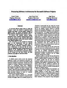
fined in NFR diagram. Figure 9 presents an portion of NFR View corresponding to a small regional office. As depicted in the figure, load requirements as s-RO-load depicted at the top left of the figure is a derived one, computed actually from serviceQoS requirements, such as appA-s1-t-r which is depicted at the bottom of the figure. A satisfy relationship may also be defined between requirements, as appA-s1-t-r serviceQoS requirement which should satisfy the corresponding service response time defined in appA-s1-RT requirement. Load requirement s-RO-load, constraint requirement s-ROcon (which refers to the existing network speed) and utilization requirement sRO-DC-util are related to each other in a way so as to be equilibrated. The system designer should be aware of this. The above views deal with the design of the applications, network topology and requirement definitions. In order to evaluate the defined architecture, a simulation study is necessary to test the performance in order to determine if the imposed requirements are satisfied. Evaluation View is represented by a Block Definition diagram, where Simulation Experiments are depicted as independent Blocks further decomposed using discrete Block diagrams. Each simulation experiment is based on the Network Infrastructure view. Corresponding diagram entities are automatically created based on Network Infrastructure view, as there is a one-to-one relationship between them. Thus, each simulation experiment is represented as a hierarchy of block diagrams, where atomic networks are described using a discrete diagram. Simulation experiment diagrams are used to initialize the executable model of the simulation engine that co-operates with the design tool. The portion of the Simulation Experiment diagram corresponding to the atomic network of figure 8 is depicted in figure 10. Each simulation entity, as local server, is described by input attributes that are computed from the attributes of the corresponding entity of Network Infrastructure View. The values of output attributes are automatically compared to the related requirement attributes and a proper indication (color deviation) is provided to the system designer to indicate which NFRs are not satisfied. It is his/her respon-
s-RO-csa-con
s-RO-csa-lod
custom service area w/s
local server
references
application-A
appA-s1
application-C
application-B
s-RO-ls-a
appA-s1-RT Id = "appA-s1-rt" Text = " " Value = "10 sec"
input:NumberofDisks input:ProcPower input:DiskCapacity input:StorageSpeed input:NumberofProcessors output:maxStorageLoad output:maxProcessingLoad output:ProcessingUtilization output:StorageUtilization
oracle R.O.
tuxido R.O.
small R.O. Officer
s-RO-ls-u
Figure 10: Evaluation View - Simulation Experiment Example sibility to modify the network infrastructure, for example server characteristics, or redesign the applications logic or to adopt a requirement relaxation. The existence of the Evaluation View helps the system designer to better realize the affect of his/her redesign decisions. The system designers in this specific case, appreciated the fact that all the information related to requirement verification was presented in a single view. They also found useful that all different experiments results were maintained and could be used when making modification in architecture design. All of them also suggested that the system could propose suggestions on system architecture modifications to satisfy imposed requirements.
6.
CONCLUSION & FUTURE WORK
Based on a proposed model-based approach for EIS Architecture design, we focused on solution evaluation task. In practice, EIS Architecture design is usually performed by properly integrating EIS components already defined by other stakeholders in an efficient manner. Furthermore, proposed architecture solutions should be evaluated and properly adjusted. The provision of a well-defined model to perform all design tasks, including system evaluation, assists the system designer when adjusting system architecture, by integrating alternative scenarios evaluations in the model. Focusing on non functional requirements and their verification using Evaluation view enhances the system designer’s perception of the way specific design decisions may affect others. SysML modeling language efficiently supported modelbased EIS Architecture design, as it provided the means to accurately depict EIS architecture and resource allocations. The proposed SysML profile is currently tested using other case studies as well. Furthermore, we are exploring the integration of EIS Architecture simulation environment and the SysML profile defined in MagicDraw tool. Information exchange between the simulation environment and SysML profile is currently under implementation.
7.
REFERENCES
[1] INCOSE Handbook SE Process Model. INCOSE, September 2003. http://g2sebok.incose.org/. [2] A. Aurum and C. Wohlin. Engineering and Managing Software Requirements. Springer, 2005.
[3] D. Brown, J. Densmore, and S. J. Vaughan-Nichols. Web services, 2002. IBM Rational Edge. [4] M. Cantor. Rational Unified Process for Systems Engineering, RUP SE Version 2.0, IBM Rational Software white paper. IBM Corporation, May 2003. [5] J. A. Estefan. Survey of Model-based Systems Engineering (MBSE) Methodologies. INCOSE MBSE Focus Group, May 2007. [6] C.-W. Ho, L. Williams, and B. Robinson. Examining the relationships between performance requirements and ”not a problem” defect reports. In RE ’08: Proceedings of the 2008 16th IEEE International Requirements Engineering Conference, pages 135–144, Washington, DC, USA, 2008. IEEE Computer Society. [7] IEEE. IEEE System and Software Engineering Architectural Description: Std 42010. Technical report, May 2009. [8] M. H. Kacem, M. Jmaiel, A. H. Kacem, and K. Drira. An uml-based approach for validation of software architecture descriptions. In TEAA, pages 158–171, 2006. [9] P. Kruchten. Rational Unified Process: an Introduction. Addison-Wesley, Reading/MA, 1998. [10] L. Lee and P. Kruchten. Visualizing software architectural design decisions. In ECSA, pages 359–362, 2008. [11] MagicDraw UML. http://www.magicdraw.com/. [12] M. Nikolaidou, A. Tsadimas, N. Alexopoulou, and D. Anagnostopoulos. Employing Zachman Enterprise Architecture Framework to systematically perform Model-Based System Engineering Activities. In HICSS, pages 1–10, 2009. [13] K. Pohl and E. Sikora. Supporting the Co-Design of Requirements and Architectural Artifacts. In 15th IEEE International Requirements Engineering Conference (RE’07), pages 258–261, India Habitat Center, New Delhi, 2007. [14] Systems Modeling Language (SYSML) Specification. Version 1.0. O. M. G. Inc, September 2007. [15] A. Tsadimas, M. Nikolaidou, and D. Anagnostopoulos. Handling non-functional requirements in information system architecture design. In ICSEA, pages 59–64, 2009. [16] XML Metadata Interchange (XMI), v2.1.1, 2007. http://www.omg.org/spec/XMI/2.1.1/PDF/index.htm.