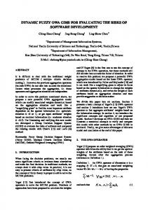
Schunk Tribos1 tool holder, were tested for their dynamic repeatability .... v (m. /N). 200. 400. 600. 800. 1000. 1200. 1400. 1600. 0. 0.5. 1 x 10. -6. Frequency (Hz).
EVALUATING THE TOOL POINT DYNAMIC REPEATABILITY FOR HIGH-SPEED MACHINING APPLICATIONS Kate M. Medicus, Tony L. Schmitz National Institute of Standards and Technology, Gaithersburg, MD Introduction Unstable cutting (chatter) can be a primary limiting factor in reaching high material removal rates (MRR) in high-speed milling. Chatter may be avoided by proper selection of machining parameters [1,2] or by tuning the tool point dynamics to increase stability at the desired machining conditions [3-6]. Both methods use the setup-specific stability lobe diagram, which divides the machining parameter space into stable and unstable regions, to select the commanded spindle speed and axial depth of cut. The stability lobes are calculated from the tool point Frequency Response Function (FRF) and specific cutting energy coefficients for the selected machining operation [7,8]. Variations in the tool point FRF, which occur due to removing and replacing the holder in the spindle, tool changes, and deviations in tool length and collet torque, change the stability lobe diagram and, therefore, affect the selection of machining parameters. In this study we replicated these variable conditions and measured the resultant FRFs. Comparisons between the FRFs indicate the dynamic repeatability of each change. The tool point FRF was measured using an instrumented hammer/accelerometer setup (Fig. 1). An instrumented hammer was used to excite the tool while an accelerometer measured the acceleration at the tool point. The FRF was then calculated from the complex ratio of the displacement (twice-integrated acceleration) and hammer Fourier transforms. The variability of the FRFs that occurred without changing the setup was established as the baseline measurement repeatability.
Two types of tool holding systems, a traditional collet tool holder and a new interference fit Schunk Tribos1 tool holder, were tested for their dynamic repeatability. Both systems used an HSK 63A holder/spindle connection. All experiments were performed on a Makino A551 high-speed CNC mill. A 12.7 mm diameter carbide tool blank was used in the collet holder, 12.0 mm blanks in the Tribos holder. In both cases, the angular orientation of all components was maintained throughout the measurements. Tool Overhang Variation A schematic of the Schunk Tribos tool holding system is shown in Fig. 2. In the resting position (Fig. 2a), the holder restricts entry of the tool. When force is applied as indicated in Fig. 2b, the holder elastically deforms and the tool is inserted. After the force is relieved, the holder relaxes to clamp the tool along three contact lines (Fig. 2c). The Tribos holder dynamic repeatability was tested at tool overhangs ranging from 6:1 to 11:1 length to diameter (L:D) ratios, in steps of one diameter using two tool blanks with lengths of 115 mm and 153 mm. At each tool length, the variation in the FRF was found when: 1) the tool holder was removed from the spindle to the tool rack and replaced (to simulate a break in machining), and 2) the tool was removed from the holder (simulating a tool change), which also required removing the holder from the spindle. Tool Holder
(a) (b) (c) Figure 2. Schematic of Schunk Tribos tool holding system operation (not to scale): a) rest position, b) force applied, and c) tool clamped. 1
Figure 1. Hammer and accelerometer setup.
Certain commercial equipment, instruments, or materials are identified to adequately specify the experimental procedure. Such identification is not intended to imply recommendation or endorsement by the National Institute of Standards and Technology, nor is it intended to imply that the materials or equipment identified are necessarily the best available for the purpose.
measurement, holder change, and tool change repeatability for the Tribos 9:1 and 11:1 tools using the point-by-point standard deviation method. As expected, the standard deviation curves follow the same shape as their respective FRFs; the uncertainty is higher at the natural frequency(s). -6
1
x 10
Measurement 0.5 0
Std Dev (m/N)
A representative FRF (magnitude component) for each tool length tested in the Tribos holder is shown in Fig. 3. Characteristic differences between the data sets are seen. In particular, the 7, 8, and 11:1 tools are single mode systems (shown by a single peak) and the 6, 9, and 10:1 tools are dual mode systems (two peaks). The dual mode systems occur due to the dynamic absorber effect [5,6] that occurs when the natural frequency of the tool approaches or matches a natural frequency of the spindle. The spindle then acts as a dynamic absorber for the tool, which results in increased dynamic stiffness. Evaluating the dynamic repeatability becomes more complicated due to this two mode behavior. Unlike the single mode data, a simple fit to determine the dynamic stiffness can not be performed. Therefore, a point-by-point comparison of the FRFs was performed.
1
-6
x 10
Holder Change
0.5 0 1
-6
x 10
Tool Change 0.5 0 200
400
600
800
1000
1200
1400
1600
Frequency (Hz) x 10
-4
(a)
1
-5
11:1
x 10 1
Measurement
0.5 0.6
Std Dev (m/N)
Magnitude (m/N)
0.8
10:1
0.4
9:1
7:1 6:1
00
400
-5
x 10 1
Holder Change
0.5
8:1 0.2
0
800 1200 Frequency (Hz)
1600
2000
Figure 3. Magnitude component of FRFs for the Tribos tool holder.
To find the baseline repeatability, five FRFs (which were each an average of ten measurements) were acquired without changing the setup. When calculating the holder change repeatability, a single FRF (which was an average of 50 measurements) was measured, the tool/holder was moved to the rack and back, and the process was repeated for a total of five FRFs. The tool change repeatability analysis followed the same process as the holder movement repeatability evaluation except the tool was removed and replaced each time. The FRF comparisons were performed by calculating the standard deviation of the set of five magnitude plots at each frequency (i.e., a point-by-point analysis). Fig. 4 shows the
0
-5
x 10 1
Tool Change
0.5 0 200
400
600
800
1000
1200
Frequency (Hz)
1400
1600
(b) Figure 4. Standard deviation of magnitude FRFs showing measurement, holder movement, and tool change repeatability for: a) Tribos 9:1 tool and b) Tribos 11:1 tool. (Note different vertical scales.)
One possible method to compare between tool lengths and between the three repeatability levels is to use the maximum standard deviations from Figure 4. But, as before, the dual mode system changes the behavior of the standard deviation curve and makes this type of comparison unacceptable. For example, an order of magnitude separate the maximum standard deviation of the 9:1 (dual mode) and 11:1 (single mode) tools. Therefore, we used the area (calculated numerically) under the standard deviation curves to make the dynamic
repeatability comparisons. See Fig. 5. As expected, the repeatability decreases (i.e., standard deviation area increases) as the mechanical complexity of the change increases from the measurement to holder change to tool change. Additionally, the repeatability generally decreases with tool length.
Fig. 7 plots collet torque versus dynamic stiffness for the collet holder data. As the torque increases we expect stiffness to increase while damping decreases. Here, the dynamic stiffness of the system increases overall, which indicates the stiffness is increasing faster than damping is decreasing.
-4
-6
x 10
1
1.8
Tool Change
1.6
Area Hz*m/N
Real (m/N)
2
1.4 1.2
x 10
f = 800 Hz
0.5
n
0 -0.5
Holder Change
-1
1
-7
x 10
0.8
0
0.4
Imag (m/N)
0.6
Measurement
0.2 6:1
7:1
8:1
9:1
10:1
11:1
Tool (L:D)
Figure 5. Area under standard deviation of magnitude FRF curves for multiple tool lengths.
1 2 kζ
-10
A
-15 -20 0
200
400
600
800
1000
1200
1400
1600
Frequency (Hz)
Figure 6. Typical FRF showing dynamic stiffness and natural frequency. 1.45
x 10
4
1.4 1.35
kζ (N/m)
Collet Torque Variation Collet-type holders clamp the tool by creating uniform pressure around its circumference. In this study, we used a torque wrench to set the collet torque, although this may not always be the case in practice. We tested the tool point dynamic repeatability for this holder type over a reasonable range of torques for this collet: (47.5, 61.0, 67.8, and 74.6) N-m. The repeatability was also determined for holder and tool changes, but only at a set torque of 61.0 N-m.
-5
1.3 1.25 1.2
1.15
The collet holder was tested with a tool overhang of 113.3 mm (9:1 L:D ratio). At this overhang, the system can be modeled as single mode; therefore, we used the dynamic stiffness directly to compare between data sets. Assuming a single mode, the minimum value of the imaginary part of the FRF (A), shown in Fig. 6, is inversely proportional to the dynamic stiffness of the system (kζ). See Equation 1, where dynamic stiffness is the product of the stiffness (k) and the damping ratio (ζ).
A=
−1 2kζ
(Eq. 1)
1.1 1.05 45
50
55
60
65
Torque (N-m)
70
75
Figure 7. Variation in dynamic stiffness with applied collet torque. Data was not collected at 54 N-m.
The error bars on the data in Fig. 7 were developed from the standard deviation of the dynamic stiffness at 61.0 N-m. The dynamic stiffness standard deviation for the measurement, holder change, tool change were, 1.99x10⁻² N-m, 3.87x10⁻² N-m, 6.22x10⁻² N-m, respectively. As with the Tribos system, the uncertainty increases with the complexity of the mechanical change. The error bars in Fig. 7 are
±6.22x10⁻² N-m, corresponding to the maximum value.
and 3) removal and replacement of the tool from the holder.
Tribos Holder vs. Collet Holder In comparing the two tool holding systems, the decrease (percent change) in repeatability from the holder change to the tool change was examined. The percent decrease in repeatability from the measurement to holder change was not compared because it was believed that a large portion of that increase is due to the removal and replacement of the accelerometer between FRF measurements.
The results showed the expected decrease in dynamic repeatability with increased mechanical complexity in the system change. Additionally, the percent variation between tool and holder changes from the collet (37%) and Tribos (33%) were similar in magnitude, which implies comparable dynamic repeatabilities. The relatively high variability in dynamic response between tool changes for both systems suggests future research on tool/holder interfaces with improved dynamic repeatability may be justified.
For the collet holder, the percent change was calculated from the standard deviation of the dynamic stiffness term at a torque of 61.0 N-m. For the Tribos holder, the percent change at each tool length was calculated from the area under the standard deviation curve; these values were then averaged to obtain an overall percent change. The percent change in repeatability from holder change to tool change was 37% for the collet holder and 33% for the Tribos holder. These results suggest two conclusions: 1) the dynamic stiffness variability associated with tool changes is not trivial and future research could focus on tool/holder interfaces that offer improved repeatability, and 2) the dynamic repeatability of the new Tribos holder compared favorably with the more well-established collet holder. Future testing should also compare these results with thermal shrink fit holders, which are common in high-speed machining applications. Conclusions In this work, the dynamic repeatabilities of two tool holding systems, a standard collet and the new Tribos holder, were evaluated under various conditions. For the collet holder, the effect of collet torque on the tool point dynamic stiffness was explored. For the Tribos system, the tool overhang was varied over a wide range. Evaluations of the dynamic repeatability were completed for: 1) no system change, 2) removal and replacement of the holder from the spindle,
References 1.
2. 3.
4.
5.
6.
7. 8.
S. Smith and T. Delio, "Sensor-Based Control for Chatter-Free Milling by Spindle Speed Selection", Symposium on Control Issues in Manufacturing, DSC-Vol. 18, ASME, WAM (1989). S. Smith and J. Tlusty, "Stabilizing Chatter by Automatic Spindle Speed Regulation", Annals of the CIRP, 41/1 (1992) 433-436. M. Davies, B. Dutterer, J. Pratt, and A. Schaut, "On the Dynamics of High-Speed Milling with Long, Slender Endmills", Annals of the CIRP, 47/1 (1998) 55-60. T. Schmitz, M. Davies, K. Medicus, and J. Snyder, "Improving High-Speed Machining Material Removal Rates by Rapid Dynamic Analysis", Annals of the CIRP, 50/1 (2001), 263268. T. Schmitz and R. Donaldson, "Predicting High Speed Machining Dynamics by Substructure Analysis", Annals of the CIRP, 49/1 (2000) 303308. S. Smith, W. Winfough, and J. Halley, "The Effect of Tool Length on Stable Metal Removal Rate in High Speed Milling", Annals of the CIRP, 47/1 (1998) 307-310. Y. Altintas and E. Budak, "Analytical Prediction of Stability Lobes in Milling", Annals of the CIRP, 44/1 (1995) 357-362. E. Budak and Y. Altintas, "Analytical Prediction of Chatter Stability Condition of Multi-Degree of Freedom Systems in Milling, Part I: Modeling, Part II: Applications", Journal of Dynamic Systems, Measurement and Control, 120 (1998) 22-36.