may be applied, and where not, and what parameters may be suggested. ... methods for which it is assumed that spatial and time gradients of the image ir-.
Computers and Artificial Intelligence, Vol. 14, 1996, No.1, 81-104
EVALUATION OF DIFFERENTIAL METHODS FOR IMAGE VELOCITY MEASUREMENT ,, !
Peter
HANDSCHACK
Graphikon, Gesellschaft fur Bildverarbeitung und Computergraphik mbH, Mandelstr. 16, D-13086 Berlin
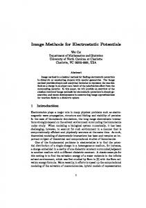
Reinhard KLETTE Fachgebiet Computer Vision, Institut fur Technische Informatik im FE 20 Technische Universitat Berlin, Franklinstr. 28/29, D-10581 Berlin Abstract. For eight point-based differential methods of image velocity measurement, including two new methods, quantitative evaluations are reported based on synthetic images, and qualitative evaluations based on real images. A new method (cluster method) is characterized by the determination of the nearest point to all constraint lines, and the other ( VF expansion method) by local approximation of the motion vector field. For six methods, solutions for algorithmic use are compiled, e.g. also iterative solutions for the Schunck and the Nagel constraint. The given quantitative evaluations 1nay be used for characterizing situations where methods may be applied, and where not, and what parameters may be suggested.
t
Keywords: image velocity, local displacement, differential methods, evaluation of methods
'tl
1 INTRODUCTION Results of image velocity measurement are often applied in modular, or integrative solutions for shape analysis or shape reconstruction [5, 9, 10]. According to [4], approaches for measuring image velocity may be classified as point-based differential methods, region based matching methods, contour-based methods, or energy-based methods. This paper deals with point-based differential
82
P. Handschack, R. Klette
methods for which it is assumed that spatial and time gradients of the image irradiance function E may be calculated. Several methods were suggested in the literature. In this paper, at first for some typical differential methods concrete formulae for algorithmic use are compiled. In some cases, such concrete specifications could not be found in literature, and they are given here for unique definition of the method as used for evaluation. Then, some general specifications for method evaluation are given and applied to the defined eight methods. The Taylor expansion for the image irradiance E = E(x, y, t) in its general·form is given by the equation E(x
+ 8x, y + 8y, t + 8t)
d2 + -12 ( -. ·E clx 2 cl2
+ -.dxay
~E
· 8x
2
d
+·E clx
= E
d2 + -. ·E cly 2
· 8y
cl · 8x +- · E · 8y ely
2+ -d2
·E
dt 2 cl2
· 8t
cl
+·E dt
· 8t
2)
d2 · 8x8y + - - · E · 8x8t + - - · E · 8y8t dxdt dydt
+h.o.t. where relatively small values 8x, 8y and 8t are assumed. This expansion may be simplified if the approximation dE 8E
dt
~
Tt'
as given in practical realizations, may be assumed for time gradients that may be calculated for a constant time interval 8t between two images of an image sequence. Then, in this Taylor expansion 8t may be eliminated. In the following · Et = Et=l - Et=O is assumed. In the sense of this approximation, U
= (n, v)T =(Ox, 8yf ~ (dx, dy)T
denotes the local displacement vector (LDV) of a certain pixel position at times t = 1 and t = 0. A local displacement vector field (LDVF) is defined by LDV's in all, or at least several pixel positions of an image at time t = 0. Unfortunately, the Taylor expansion is a non-linear equation for calculating vector's u(x, y).IDifficulties with the non-linearity would increase with the application of additional. solution conditions, as e.g. the smoothness constraint considered below. For the derivation of the " classical" Horn-Schunck constraint u · \7 E
+ Et
= 0,
mathematically the following Horn-Schunck ass1tmption was used: the difference D = E(x
+ 8x, y + 8y, t + 8t) -
E(x, y, t)
'p
83
Evaluation of differential methods
is equal to the non-linear terms in the Taylor-expansion, e.g. for constant surface irradiance the difference D would be zero, and for "planar patches" of E, the non-linear terms in the Taylor-expansion would be zero. Thus, theoretically this constraint is especially true for interior areas (i.e. no discontinuities as edges) of Lambertian surfaces. It may be suggested to use also higher order terms in the Taylor expansion of function E. Besides the numeric errors in computing higher order derivations there is the serious problem in applying non-linear smoothness constraints for such "improved constraints" . The numeric and algebraic complexity would increase beyond what seems to be solvable. See also Section 3.1 for some experiments with second order expansions.
The paper is organized as follows: In Section 2, the eight methods implemented for evaluation are described. The evaluation approach (e.g. error measure, used images, details of implementation as local operator size or depth of Taylor expansion) is explained at the beginning of Section 3, followed by the results of this evaluation for synthetic and real images. A summary is given in Section 4.
2 DIFFERENTIAL METHODS FOR OPTICAL FLOW COMPUTATION The Horn-Schunck constraint has some drawbacks as mentioned already by Horn and Schunck themselves, the rotation problem: rotation in R3 may be respected only if the rotation axis is parallel to the light direction, and the uniqueness problem: single points (x, y) specify only one linear equation in two unknowns 1t and v.
For Ex · Ey =f. 0, the LDV u points to an unknown point on the constraint line, see Fig. 1. Without additional information, this result can not be improved in general. Unique solutions are possible for some very specific local functions E, cp. [12], so-called "gray value corners" . In several approaches the Horn-Schunck assumptions are accepted, and certain additional constraints for the LDVF are formulated and used for solving the uniqueness prpblem, or even both the uniqueness and rotation problems. Often applied is the simple smoothness constraint of a "locally smooth LDVF" , formally defined by
~sm = ( ~~)
2
+ ( ~~) + ( ~~) + ( ~~) 2
2
2
=}minimum.
Based on the Horn-Schunck constraint and the simple smoothness constraint, several methods may be suggested for computing LDVF's as methods (i) ... (v) described below.
84
P. Handschack, R. Klette
u constraint line Fig. 1. Constraint line for E, · Ey =/= 0.
2.1 Algebraic Methods The following methods (i) ... (iv) may be characterized as algebraic. They are based on the Horn-Schunck constraint and the simple smoothness constraint. (i) Pseudo-inverse method: For n pixel positions (x1, yl), . .. , (xn, Yn) the simple smoothness constraint is assumed, i.e. the constraint lines of these n points should cross (nearly) in one point u = (u., v) defining the LDV. This point u may be calculated by solving the equation system
This equation system will be over-determined for n > 2 in general. By using the pseudo-inverse M' = (MTM)- 1 MT of matrix M, the solution u = -M' · Et may be used [7]. This is called the pseudo-inverse method in the following which is selected in the evaluation section for representing methods (i) ... (iv). (ii) The ~ucas and Kanade method: By Lucas and Kanade, certain refinements of the pseudo-inverse method (weighting of the point equations with respect to the distance of the point to the reference point by a Gaussian mask, iterative improvement of LDVF's) were suggested [1]. (iii) The cluster method: This new method is based on the assumption, that point u should be as close as possible to all the n constraint lines 1'i
= u · cos (Pi
+ v · sin ¢i
(Hessian normal form)
I•
85
Evaluation of differential methods
of n pixel positions where the simple smoothness constraint may be applied. By LSE minimization, the solution u = ( u, v) has to satisfy S =
;}
L wi · (tt ·cos ¢i + v ·sin ¢i- ·ri)
2
::::}
minimum,
where the Wi 's are proportional to the inverse distance of the pixel position to the actual reference point. The solution u = (u, v) may be calculated by solving the equation system
which may be called the cluster method because of its similarity to cluster techniques for geometric object detections. (iv) The VF expansion method: For this new method 1 , a local approximation (based on Taylor expansion of u) of the LDVF is used. Assuming the HornSchunck constraint and the simple smoothness constraint in "small pixel environments" U(p ), with q E U(p ), it is assumed for point p = (x, y) that the LDV u = (u(p),v(p)) satisfies
S=
L
w(q) · (Ex(q) ·tt(q)
+ Ey(q) · v(q) + Et(q)) 2 ::::} minimum.
qEU(p)
Let
ExEy =
L
w(q) · Ex(q) · Ey(q).
qEU(p)
Following [16], the LDVF u may be approximated by a Taylor expansion with respect to points in U (p). If only the first term ('u 00 , v00 ) T of this expansion is used as approximatiOit of the desired solution (u, v), then this leads to the equation system
Assuming these simplification to the general Taylor expansion, this solution is formally nearly the same as the solution of the cluster method. In the more general 1
Suggestion by Klaus Voss, Jena University.
86
P. Handschack, R. Klette
case of using also first order derivatives (n 10 ,v10 )T and (u 01 ,v01 )T, the method leads to improved results but needs much computation time. In our implementations, these methods (i) ... (iv) did lead to algorithms with about the same behavior for the used synthetic pictures and assumed motions. Thus, these methods (i) ... (iv) may be represented in the evaluation section typically just by one method for simplifying comparisons and figures. But, with respect to computing time, and with respect to given images and motions, these different methods may be worth of comparing in specific applications.
2.2 Methods Based on Variation Calculus Method (v) below may be called the classical way for measuring image velocity. Besides the Horn-Schunck constraint and the simple smoothness constraint as assumed for m~thdds (i) ... (v), also different constraints may be assumed for function E. Here, three further approaches (vi) ... (viii) described below were selected for comparison which are often referenced in the literature. Methods (v) ... (viii) are based on the variation calculus [14]. Let~~ be the error of the defining constraint with respect to u, e.g. the Horn-Schunck constraint, and ~;m the error of the smoothness constraint with respect to u. Let a 2 be a weight of the "smoothness strength" . For solving the optimization problem
e = JJ(a2 ~!, + a)dxdy::::} minimum, in all relevant pixel positions (x, y), certain Euler-Lagrange differential equations will be calculated as necessary condition that u determines such a minimum. In these equations, the Laplace operator \7 2 (it appears in the solution of the Schunck method), as first derivations Ex, Ey or Et in the coefficients, may only be approximated for a discrete function u(x, y), e.g. by
[6]. This lead~ to an iterative solution. A solution of the system of Euler-Lagrange differential equations would be an alternative choice. Let u(i) = (u(i), v(i))T be the solution in step i. For averaging of results in step i, in case of 3 x 3 local operators the mask
1
12
1 2
1
2 0 2
1 2
1
87
Evaluation of differential methods
is used for computing v;( i) and v( i). In general, for approximation of first and second order derivations, common 3 x 3 . . . 5 x 5 local operators may be used, see e.g.
[16]. (v) Iterative method by Horn and Schunck: In [6], the iterative solution for computing LDVF is based on ~G = (Exu + Eyv + Et) 2 and ~;m = u; + u~ + v; + v~. The iteration formulae are u(i+l) =
v;(i) _
(i+l) _ -(i) _
v
Ex · (Exv;(i) + Eyv(i) a 2 +E'f, +E'f, Ey · (Exu(i)
- v
2 (X
+ Et)
+ Eyv(i) + Et)
E2
+ X+ E2X
and .
This will be called the Horn-Schunck method in the following. (vi) Iterative method for the Schunck constraint: Schunck himself suggested in [15] the use of the following constraint, · u · '\1 E
+ Et + E
· \lu = 0.
By his opinion, the additional term should relax the rotation problem. No mathematical proof was given in [15] for this statement. For minimization of ~b = Extt + Eyv + Et + Eux + Evy and applying the simple smoothness constraint, i.e. minimization of c2 '>sm
2
= Ux
+ Uy2 + Vx2 + Vy2
no derivation of an iterative solution could be found in the literature and will be sketched here for being precise about what method has been implemented for evaluation. By applying the variation calculus, a necessary condition for a relative is given by the following Euler-Lagrange differential extreme of the function equations
e
ExxU + Euxx
a2
+ 2ExUx + ExVy + EyVx + EyxV + Evyx + Etx + E · '\1 2 u =
and
The equation system
(~~ -
E,,) u- EyxV =A, a2
A = EUxx
+ 2E,1tx + ExVy + EyVx + EVyx + Etx + E ·U,
- E,ytt +
(~ -
B
I.
Eyy) v
= B,
= Evyy + 2Eyvy + Eyux + E,uy + Euxy + Ety +
a2
E ·v
0
88
P. Handschack, R. Klette
leads to the iterative solution
and
This is called the Schunck method in the following. (vii) Iterative method for the Nagel constraint: In [13], the Horn-Schunck constraint, whicJ:t may be accepted in case of parallel projection, was modified by studying the impact of central projection on deriving a constraint from the Taylor expansion. Assume the camera-centered coordinate system in the 3D space, cf. for example case ccc in [9]. For focal length b, point P = (X, Y, Z) is mapped onto point p = (x,y) = (bXjZ,bY/Z) in the picture plane Z =b. Let k be the unit vector in Z-direction, i.e. it holds that k · P = Z. Assume a translation U of point P. In the Nagel constraint
+ Et -
u · \l E
4E ·
k·U P·U) -- - = 0, (k·P p.p
vectors P and U in 3D space are unknowns, and vector U is mapped onto vector u = (u, v) T in the picture plane Z = b. It holds that b (x,y,b)=k·P·P ( 1t, v,
and
T b b ) 0) = (k. P) 2 · k x (U x P) = (k. P) 2 · ((k · P) · U- (k · U) · P .
Following [19], the Nagel constraint may thus be written as
u . \l E
u·p
+ Et + 4E · p·p+ b2
= 0
or Ex1t
+ Eyv + Et + 4E ·
X
2
ux :2 b +y + 2
+ 4E ·
vy 2
X.
+y 2 +
b2 =Au+ Bv + Et
with
A=E x
+
x2
4E·JxJ
+ y2 + b2
and
B = Ey
+
4E ·JyJ 2 X
+y 2 +
b2 .
2
=0
89
Eval'Uation of differential methods
For algorithmic use of this constraint, i.e. minimization of ~b =Au+ Bv and applying the simple smoothness constraint, i.e. minimization of
+ Et,
also here, a derivation of an iterative solution could not be found in the literature. By applying the variation calculus, we have the following iteration formula
(A) .
:a(i)
u(i+l)
= :u(i)-
B
a:2
+ Et
+ A2 + B2
.
(A) . B
This is called the Nagel method in the following. (viii) Nagel-Enkelmann method: The simple smoothness constraint as used so far may be i-efined in relation to local gradients of the irradiance function E. In [3, 11], the following refined smoothness constraint was suggested,
where in the matrix F- a2.
(10
the first summand corresponds to the simple smoothness constraint (with weight a 2 ), the second models smoothness orthogonal to the local gradient of irradiance function E (with weight b2 ), and the third models smoothness orthogonal to the local main curvature of function E (with weight c2 ). In this refined smoothness constraint, trace(F) is used for normalization. The simple smoothness constraint corresponds to a 2 = 1 and b2 = c2 = 0.
itera~ive solution u(i+l) = u(i) +Du and p = (x, y) let E 1 = E(p-u(i), t)
For an and E2 = E(p, t
+ 15t).
The variation problem
e :::} minimum, with
2 Absolute values because optical axes of pinhole camera is assumed to pass the image plane at the mid point.
90
P. Handschack, R. Klette
leads to the solution (111 denotes an a-priori parameter: the center weight of the digital operator mask used to determine the partial derivatives)
as proved in [3] where the overbar indicates the averaging over all positions q in the neighborhood of point p - uCil. This will be called the Nagel-Enkelmann method in the following.
3 EVALUATION AND COMPARISON In [8] a qualitative, theoretical analysis of error sources for point-based differential methods is given. There are already some reports in the literature on quantitative evaluations of different approaches for motion measurement. For example, in [19] the absolute errors of the Horn-Schunck, the Schunck, and the Nagel constraint were computed for central projection of a sphere, i.e. these constraints are evaluated for a specific projection, but not certain methods for measuring image velocity. By these studies, some basic statements are possible, • maximum errors appear at motion and image value edges, • errors and their variance increase with motion speed, • the Horn-Schunck constraint and the Nagel constraint lead to similar results, and the Schunck constraint increases the errors. It was in [1, 2, 18] for the first time to study how calculated LDVFs differ from the ideal LDVF using specific methods. In the following, such studies are reported for methods (v) ... (viii) and method (i), (i) as representative of methods (i) ... (iv), for synthetic images.
3.1 Specifications for Qualitative Evaluation
For the realized evaluation, information is given (I) about the type of used images and the related model of scene projection, (II) the measure( s) used for quantitative evaluation, (III) the used algorithms and (IV) the statistical relevance of the evaluation data. (I) The synthetic images were selected for simulating translations and rotations of patterned (regular patterns, wave images, see. Fig. 2) or textured (pseudorandom patterns, texture images) planes in 3D space. Wave images were generated
91
Evaluation of differential methods
for homogeneous motions of an object plane in XY Z-space, assumed to be parallel to the xy-image plane, with regular wave patterns in X- and/or Y-direction representing ideal waves of wave length l. .Texture images were generated also for object motions in this object plane. Each texture image contains non or at most one homogenous textured planar object region on a homogeneous textured background.
··
The image resolution was 64 x 64, the focal length was assumed to be 100 pixel, and the distance of the object plane to the image plane was assumed to be 1000 pixel. Parallel lighting was assumed for the object plane. Translations in the object plane are specified by numbers of pixels (e.g., a 10 pixel translation in X-direction results in a 1 pixel translation in x-direction in the image plane), and rotations by degrees.
..... •.••............
..:··!'!!:·::·:ol.!.'·!!'?.!.'-''•'!'!'•!!·~··:~···:·::o: