within the common multithreaded programming model ... unified model, application programmers perform ... Dedicated hardware threads require no context.
Evaluation of the Hybrid Multithreading Programming Model using Image Processing Transforms Razali Jidin, David Andrews, Wesley Peck, Dan Chirpich, Kevin Stout, John Gauch Information Technology and Telecommunications Center Department of Electrical Engineering and Computer Science University of Kansas {dandrews,rjidin,peckw}@ittc.ku.edu} Abstract Hybrid chips containing both CPU's and FPGA components promise the potential of providing a unified platform for seamless implementation of hardware and software co-designed components. Realizing the potential of these new hybrid chips requires new high level programming model capabilities that support a far more integrated view of the CPU and FPGA components than is achievable with current methods. The KU Hybrid Threads project has been investigating extending the familiar multithreaded programming model across this CPU/FPGA boundary to support both FPGA based hardware and CPU based software threads. Adopting this generalized multithreaded model can lead to programming productivity improvement, while at the same time providing the benefit of customized hardware from within a familiar software programming model. In this paper we present an application study of our hybrid multithreaded model. We have implemented several image-processing functions in both hardware and software, but from within the common multithreaded programming model on a XILINX V2P7 FPGA. This example demonstrates hardware and software threads executing concurrently using standard multithreaded synchronization primitives transforming real-time images captured by a camera and display it on a workstation.
Ptolemy [2], Rosetta [6], and System-C [3] are investigating system level specification capabilities that can drive software compilation and hardware synthesis. Other projects such as Spark [12], Streams-C and Handel C are focused on raising the level of abstraction at which FPGAs are programmed by augmenting the C language. System Verilog and a newly evolving VHDL standard are also now being designed to abstract away the distinction between the two sides of the traditional low level hardware/software interface into a system level perspective. Although these approaches differ in the scope of their objectives, they all share the common goal of raising the level of abstraction required to integrate hardware and software components. The KU hybrid threads project has been focused on extending the familiar multithreaded programming model to abstract the FPGA/CPU components, bus structure, memory, and low-level peripheral protocols into a transparent system platform [8]. Our hybrid multithreaded programming model allows the specification of applications as sets of threads distributed flexibly across the system CPU and FPGA assets. In next section, we provide an overview of our hardware hybrid thread synchronization primitives – spin locks, blocking locks and blocking counting semaphores. We then describe our image processing application using our synchronization primitives and provide performance comparisons with similar software implementations.
1. Introduction
2. Overview of Hybrid Thread
Recently emerging hybrid chips containing both CPU and FPGA components are an exciting new development that promise COTS economies of scale, while also supporting significant hardware customization. Researchers are investigating new design languages, hardware/software specification environments, and development tools to tap full potential of these hybrid chips. Projects such as
General programming models form the definition of software components, and governing interactions among the components [1]. Achieving abstract programming capabilities across the FPGA/CPU boundary requires adaptation of a high-level programming model that abstracts the FPGA and CPU components, bus structure, memory, and low-level peripheral protocol into a transparent computational platform [8]. The KU hybrid
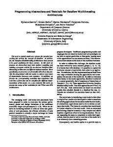
threads project has chosen a multithreaded framework as our model, supporting concurrent hybrid threads distributed flexibly across the systems CPU and FPGA assets. Within our model, all threads adhere to the policies of accepted shared memory synchronization protocols for exchanging data and synchronizing control. To support this generalized model across the FPGA, we have developed a Hardware Thread Interface that encapsulates mechanisms to support synchronization for FPGA based threads. Under this unified model, application programmers perform procedure calls from within both VHDL and C to access high level synchronization primitives between threads running across both hardware and software computations. The set of Hardware Thread Interface components as well as a standard software interface component form our system-level hybrid thread abstraction layer as shown in Figure 1. CPU
Software Thread1
Software Thread 2
Software Thread Interface Component
system bus Hardware Threads Hardware Thread Interface Component
Hardware Thread Interface Component
User Hardware Thread 1
User Hardware Thread 2
Hybrid thread abstraction layer
Figure 1. Hybrid thread abstraction layer
2.1. Hardware Thread Support We provide our Hardware Thread Interface component as a library for inclusion within user-defined hardware threads. The hybrid thread abstraction layer implements all interactions between source hardware threads and other system components through the command and status registers. This capability is particularly useful for debugging and is used during runtime to interact with all other system components, such as our semaphore IP for thread blocking and wake-up. During debug, the status register is accessible from user programs allowing developers to monitor and control the execution state of a hardware thread. We implement the Hardware Thread Interface component library as three subcomponents: a CPU
interface, a hardware-thread state controller, and a user hardware-computation interface. The user interface binds our device independent API’s accessible from within the application program to platform-specific implementation methods. Thus the HTI component provides a generalpurpose register set that supports platform independent user level semantics to promote thread migration across the system. The controller state machine controls the execution of a user hardware thread, which will be in one of three states: idle, running, or waiting. Threads that have not yet started or have terminated are in the idle state. Threads that are currently in the run state transition into the wait state when a thread requests a semaphore, or continues to be blocked on a semaphore. Each hardware thread’s state is maintained in the status register. Dedicated hardware threads require no context switching when transitioning the thread into the wait state. Instead, the hardware thread simply idles. This allows the adoption of the same approach for both spinning and blocking semaphores. The hardware thread interface component, however, does perform different processing for spinning and blocking semaphores. For the spinning semaphore, the hardware thread interface transitions the thread state into the wait state, issues a single request for the semaphore, and return the thread to the running state when the request’s status is returned in the status register. The thread then checks to see if it owns the semaphore or not. In contrast, for the blocking semaphore, the hardware thread interface transitions the thread to the wait state, issues the request for the blocking semaphore, and leave the thread in the wait state while semaphore is in use. Upon grant or release, the state machine will then transition the thread back into the run state. User threads use standard API’s to request system services through the user hardware-computation interfaces. The API writes an op_code into the operation register and waits for the controller to respond. The controller services requests initiated from user threads through the API’s and updates the status register appropriately. The user thread request op_code, API and status register return codes are given in Table 1.
2.2. Hybrid Thread Synchronization We implement efficient synchronization mechanisms that are CPU family independent, and require no additional control logic to interface into the system memory coherence protocol. As such, our new mechanisms are easily portable across shared and distributed memory multiprocessor configurations and are also available on CPU/FPGA systems with only software threads.
A single read operation is used to request a semaphore. We use the address lines to encode both the semaphore ID and thread ID during a normal bus read operation. The control structure within the semaphore IP then conditionally accepts or denies the request during a single read bus operation. We implement multiple semaphores within on chip BRAM, thus minimizing the number of CLB’s that are traditionally used to implement the individual registers. The semaphore ID that is encoded within the address is directly decoded to select the semaphore in the BRAM. Table 1. Hardware Thread API Pseudo API Read_data( ) Write_data( ) Sem_post( ) Sem_wait( ) Mutex_lock Mutex_Unlock Spin_lock( ) Spin unlock( )
Opcode READ WRITE WRITE SEMWAIT MTXLOCK WRITE SPINLOCK WRITE
Return Code READ_OK WRITE_OK SEM_POST_OK SEM_WAIT_OK MTX_LOCK_OK MTX_UNLK_OK SP_LOCK_OK SP_UNLK_OK
suspended thus enabling more efficient usage of the computing resources and decreasing congestion on the system bus. In many operating systems, each blocking semaphore resource is associated with a sleep or wait queue. As the total number of synchronization variables in a system may be quite large, implementing separate queues for each semaphore would require significant FPGA resources. Our approach is to create a single queue for all blocking semaphores. The queue size is an initial design parameter that is set to the total number of threads that can run concurrently within the system. Even though there will be many sub-queues associated with different semaphores, the combined lengths of all semaphore queues should not be greater than the total number of threads in the system as sleeping threads cannot make additional requests for other semaphores. Releasing a blocking semaphore triggers de-queuing of the semaphore’s next owner. To manage the global queue efficiently, we created a single waiting queue that is divided into four tables - Queue Length, Next Owner Pointer, Last Request Pointer and Next Next-Owner.
Owner registers
2.2.1. Binary Spin Lock Semaphores
Thread_7 Thread_1
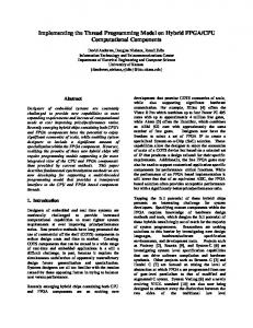
The block diagram for a (multiple) spin lock IP is shown in Figure 2. This single entity provides control for sixty-four spin locks. To request a semaphore, the spin_lock( ) API issues a single atomic read to an address formed by encoding the semaphore ID and thread ID as the least significant bytes of the base address. In response to this read operation, the spin lock controller decodes the address line and extracts both the semaphore and thread ID’s. The extracted thread ID is then compared with the thread ID stored in the owner register to determine if the semaphore is empty or currently in used. If the owner register is free, it will be updated with the requested thread ID. If the lock is currently locked, then the control logic performs no update. After the check is performed, the controller places the appropriate thread ID from the current owner thread id onto the data bus and terminates the bus cycle. The controller takes eight cycles to complete the request. To release the semaphore, the API writes its thread ID to an appropriate address. The controller state machine then decodes the address lines and updates the selected owner register to non-owner status. 2.2.2. Blocking Synchronizations Blocking synchronization allow threads that cannot gain access to the semaphore to be queued and
Controller Address bus: 6 lines for spin lock id 9 lines for thread id 2 lines for operation code
Data Bus
Figure 2. Multiple Spin Lock The Queue Length Table maintains the length of each semaphores queue, and is accessed by indexing into the table with the semaphore ID. The Last Request Table contains a thread ID or pointer to the Next-next owner table. This table is also indexed by the semaphore ID. The table is used to point to the last semaphore request. The Next Owner Table contains the next owner thread ID, which is also a pointer to Next-Next-Owner Table. When a semaphore is released, this pointer is used to provide next semaphore owner. Then it will be updated with new next owner by reading the next-next owner table. It is indexed semaphore ID. The Next-Next owner serves to provide a linked list between all the next owners of a given semaphore. It is indexed by a thread ID.
2.2.3. Blocking Binary Semaphores The block diagram for a (multiple) block lock (MUTEX) IP is shown in Figure 3. This single entity carries sixty-four block locks (64 owner registers in BRAM). In addition to the owner registers, there is a wait queue to hold the thread ID’s of blocked threads. Owner registers Thread_9 Thread_7
Thread_1
Tables Link Pointer Last Request Next Owner Queue Length
If the counter value is non-zero, the controller decrements the counter by one, otherwise extracted thread id is en-queued. If the returned value is zero, the API puts the thread to sleep.
Controller - mutex or blocking lock - tables/queue - bus master Address bus: 6 lines for mutex id 9 lines for thread id 2 lines for operation code
To request for a semaphore, the sem_wait( ) API issues a read to an address formed by encoding the semaphore ID and thread ID as the least significant bytes of the base address. In response to this read operation, the controller decodes the address line and extracts both the semaphore and thread ID’s. The controller reads the counter pointed by the extracted semaphore ID, places the read value on data bus, terminates the bus cycle, and perform additional operations depending on the value of the counters.
Data Bus
Counters
Tables
0 4 0
Link Pointer
3
Last Request
5 4
Queue Length
Figure 3. Blocking Binary Semaphore This single queue holds all thread id’s blocked on any of the sixty-four block locks. The controller responds similarly to the controller response for a spin lock. However, if the lock is not free, the appropriate queue length will be updated and the requested thread ID will be queued. The controller takes eight cycles to complete the request. To release the semaphore, the API writes its thread ID to the release register. The controller will decode the address lines and update the selected owner register to non-owner status if the queue is empty. If the queue length of selected semaphore IDs is non zero, then the queue length is decremented and the next owner pointer will be read to de-queue a next owner thread ID, and the owner register will be updated with the next owner accordingly.
Next Owner
Controller - semaphore - tables/queue - bus master Address bus: 6 lines for semaphore id 9 lines for thread id 2 lines for operation code
Data Bus
Figure 4. Blocking Counting Semaphore The API pseudo code for blocking counting semaphore is shown in Figure 5. To release the semaphore, the sem_post( ) API write its thread ID to an appropriate address. The controller state machine then decodes the address lines and reads the selected counter.
2.2.3. Blocking Counting Semaphores The block diagram for a multiple blocking counting semaphore is shown in Figure 4. This entity carries sixty-four counting semaphores (64 counters in BRAM). In addition to the counters, there is a wait queue to hold the thread ID’s of blocked threads. This single queue is designed to queue all threads blocked on all of the sixty-four semaphores.
If the selected counter is non-zero, it will incremented by one. Otherwise if the counter is zero, the controller proceeds checking the queue length of the selected semaphore. If the queue length is zero, the counter will be incremented. If the queue is not zero, the next semaphore owner will be de-queued and the counter will not be updated.
sem_wait(sema_id, thread_id) { address out = addr2; //Hardware thread create API hw_thread_create(address1, address2, algorithm ) while (1) { // Get image from ethernet receive(img->in, img_size) / / Let hw thread know image data is available sem_post( &sema1 ); //Wait for hw thread finish processing sem_wait( &sema2 ); // Send processed image send(destination, img->out, img_size); } } Figure 7. CPU Software thread, part of C program
Upon receipt of the semaphore post (S1) operation from the software, the semaphore IP writes a wakes-up command to the blocking hardware thread (write it the hardware thread command register). The hardware thread awakes, reads the image from the heap, performs the image processing specified within the thread, and writes the processed image back into the heap at location provided by the second pointer variable. When the hardware thread finishes processing all the image pixels, it performs a post on semaphore S2 to signal the completion processing of the image frame to the software thread. The posting on semaphore S2 causes the sleeping software thread to wake and initiate transferring the processed image frame back to the workstation for display. The hardware thread user component shown in Figure 6 is divided into two parts – a control unit and a data path. The control unit initiates requests to the hardware thread interface for accessing data and performing the synchronization operations. Addresses for accessing data from the SDRAM are generated by the control unit too. For several of our simple image processing functions such as gray scale inversion and threshold, the control unit is represented in the following five states: 1) semaphore wait, 2) read, 3) waiting for process to complete, 4) write and 5) semaphore post. The pseudo code for these five states is shown in Figure 8. The VHDL code for this hardware thread pseudo code that use API is given in Figure 9. If command == run SW: sem_wait( &sema1 ) RD: read data processing wait write data if count == image_size RD: else SP: SP: sem_post ( &sema2) branch SW Figure 8: Hardware thread control code pseudo code The data paths consist of logic for transforming data to the desired output. For the median filter algorithm, the data path is given in Figure 10, and consists of a frame buffer, a module to handle boundary conditions, and nine 8-bit comparators that produce medians of the nine pixels. The median filter operates at 100 MHz, and is capable of producing a new 8-bit pixel value every clock cycle. We have implemented four separate image-processing algorithms in VHDL. As our FPGA hardware
resources are limited, we have implemented a minimal image- processing buffer size. For example for the median filter or the binomial filter, we have implemented a frame buffer that sizes up to about double of image width in byte ((image width * 2 + 3) * 8 bit). when sem_wait => semw1: sem_wait(base_addr, sema1, operation); if thread_status = SEM_WAIT_OK then reset_count