Example 1: Transfer function of an interacting system
Recommend Documents
2 (1979) 147-150. 147. AN EXAMPLE OF A BLOCH FUNCTION. RICHARD M. TIMONEY. Department of Mathematics. Indiana University. Bloomington, Indiana.
introduce new and important signalling dynamics in the players' strategies. ... The trading game (Figure 1) has a unique equilibrium (L, N). Buy(B) Not Buy(N). High ... action a â {H, L} with probability ËÏt(a) at time t and the strong seller pla
Keywords: Experimental investigation; swirling jets; flow interaction; ... such as diffuser geometry, initial velocity, swirl number, gap between jets, blown jets ...
An example. Most of the results below will be described in the context of a simple in- finitely repeated trading game. The row player is a seller who can produce.
Dynamic and repeated games typically have many equilibria and reputation results allow us to determine which equilibria continue to be played when a game is.
Bernecker SL, Coyne AE, Constantino MJ, Ravitz P. 2017. For whom does interpersonal psychotherapy work? A systematic review. Clin. Psychol. Rev. 56:82â93.
countless discussions on the theory of interacting particle systems. ..... particle system is its definition as a Markov process with values in a suitable compact.
Aug 9, 2005 - space M will be denoted by q = (q1,··· ,qN ) and a generic element of the ... dynamics for the computation of phase space integrals of type (1). How- .... We adopt here the physical names of these stochastic processes, which.
Jun 3, 2014 - Three structurally and functionally related α1-subunit (CaVα1) families are distin- guished, CaV1.x, CaV2.x, and CaV3.x (Figure 1C).
Similarly, area âB + area âD = area ABCD. (Note that the proof is no longer valid when the quadrilateral becomes concave, i.e. when one of the angles of the ...
cartographic product development by means of the House of Quality. .... The House of Quality (matrix) is the most recognised form of QFD, and takes its name ...
Dec 22, 1997 - (Received 15 August 1997). The dynamics of a magnetic particle system consisting of ultrafine Fe-C particles of monodisperse nature has been ...
Mar 17, 2015 - We focus on caloron-Dirac string interaction and show that the metric that Diakonov and Petrov offered works well in the limit where this ...
(65) Davidson, J.A., Werner, M.W., Wu, X., Lester, D.F., Harvey, P.M., Joy, M., Morris,. M. 1992 ... (90) Sandqvist, A., Wootten, A., & Loren, R.B. 1985, AA, 152, 25.
Nov 19, 2014 - We describe a new code to simulate the stellar evolution of a close interacting binary system. It is then used to calculate the evolution of a ...
Sgr Aâ is a bright, compact radio source at the dynamical center of the Galaxy which was discovered ... has been found to lie within the inner 0.015 pc of the Galactic center. (0.1â²â² .... These studies of gas motion over the last 20 years ... i
experimental study of an interacting maghemite nanoparticle system [11], it was not ... Still, the particle system exhibited non-equilibrium dynamics in magnetic ...
to 800 Astronomical Unit (A.U. is defined as the average distance between the .... Within the cavity of molecular gas in the CND lies the ionized gas known as ...
Jun 5, 2015 - For either type of interaction we find that the feedback control can lead to an ... space the feedback control induces oscillations of the mean velocity. ... charges on the particles' surfaces, or (solvent-induced) ..... ues vmax and vm
Abstract: Soft X-ray tomography (SXT) is becoming a powerful imaging technique to analyze eukaryotic whole cells close to their native state. Cen- tral to the ...
core business processes in the three offices situated at different locations in ..... Finance: The existing accounting software (Sage) has now been linked with the.
Feb 11, 2015 ... View Proposal for Academic Staff Professional Development Grant ... the "...most
comprehensive sports medicine and exercise science event in ...
The bedrock at the western ice margin is composed of rocks of Hecla Hoeck for- mation represented by ..... Mining and Metallurgy. VAN DER MEER, J. J. M., ...
Ïs,B,1 of B depends only on Ï -1 (Tab. 1) k. B. / s-1. Reactant A. Product B Ï s,A,1. / rad s- ... Modeling an unsteady-state isothermal CSTR with typical first-order.
Example 1: Transfer function of an interacting system
An example of a control system with multiple signal paths is a multi-legged robot.
... A similar analysis can be accomplished using block diagram reduction ...
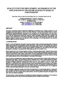
Example 1: Transfer function of an interacting system A two-path signal-flow graph is shown in Figure (a) and the corresponding block diagram is shown in Figure (b). An example of a control system with multiple signal paths is a multi-legged robot. The paths connecting the input R(s) and output Y(s) are P1 = GXG2G2GA (path 1) and P2 = G5G6G7G8 (path 2).
There are four self-loops: L1= G2H2, L2 = H3G3, L3 = G6H6, and L4 = G7H7. Loops L1, and L2 do not touch L3 and L4. Therefore, the determinant is ∆ = 1 - (L1 + L2 + L3 + L4) + (L1L3 + L1L4 + L2L3 + L2L4). The cofactor of the determinant along path 1 is evaluated by removing the loops that touch path 1 from A. Hence, we have L1 = L2 = 0 and ∆1 = 1 - (L3 + L4). Similarly, the cofactor for path 2 is ∆2 = 1 - (L1 + L2)
1|P a g e
Dr.Laith Abdullah Mohammed
A similar analysis can be accomplished using block diagram reduction techniques. The block diagram shown in Figure (b) has four inner feedback loops within the overall block diagram. The block diagram reduction is simplified by first reducing the four inner feedback loops and then placing the resulting systems in series. Along the top path, the transfer function is
2|P a g e
Dr.Laith Abdullah Mohammed
Example 2: Transfer function of a multiple-loop system A multiple-loop feedback system is shown in Figure in block diagram form. There is no need to redraw the diagram in signal-flow graph form, and so we shall proceed as usual by using Mason's signal-flow gain formula. There is one forward path Px = G1G2G3G4. The feedback loops are
EXAMPLE 3: Transfer function of a complex system Consider a reasonably complex system that would be difficult to reduce by block diagram techniques. A system with several feedback loops and feed forward paths is shown in Figure below. The forward paths are
3|P a g e
Dr.Laith Abdullah Mohammed
Signal-flow graphs and Mason's signal-flow gain formula may be used profitably for the analysis of feedback control systems, electronic amplifier circuits, statistical systems, and mechanical systems, among many other examples.
4|P a g e
Dr.Laith Abdullah Mohammed
EXAMPLE 4: The position control system for a spacecraft platform is governed by the following equations:
Sketch a signal-flow diagram or a block diagram of the system, identifying the component parts and their transmittances; then determine the system transfer function P(s)/R(s). Solution:
5|P a g e
Dr.Laith Abdullah Mohammed
Question 1: A four-wheel antilock automobile braking system uses electronic feedback to control automatically the brake force on each wheel. A block diagram model of a brake control system is shown in Figure below, where Ff(s) and FR(s) are the braking force of the front and rear wheels, respectively, and R(s) is the desired automobile response on an icy road. Find Ff(s)/ R(s).
Question 2: Off-road vehicles experience many disturbance inputs as they traverse over rough roads. An active suspension system can be controlled by a sensor that looks "ahead" at the road conditions. An example of a simple suspension system that can accommodate the bumps is shown in Figure below. Find the appropriate gain K1 so that the vehicle does not bounce when the desired deflection is R(s) = 0 and the disturbance is Td(s).