IEEE TRANSACTIONS ON SOFTWARE ENGINEERING,
VOL. 36,
NO. XX,
XXXXXXX 2010
1
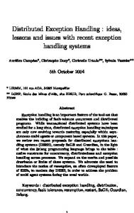
Exception Handling Patterns for Process Modeling Barbara Staudt Lerner, Stefan Christov, Student Member, IEEE, Leon J. Osterweil, Member, IEEE, Reda Bendraou, Udo Kannengiesser, and Alexander Wise Abstract—Process modeling allows for analysis and improvement of processes that coordinate multiple people and tools working together to carry out a task. Process modeling typically focuses on the normative process, that is, how the collaboration transpires when everything goes as desired. Unfortunately, real-world processes rarely proceed that smoothly. A more complete analysis of a process requires that the process model also include details about what to do when exceptional situations arise. We have found that, in many cases, there are abstract patterns that capture the relationship between exception handling tasks and the normative process. Just as object-oriented design patterns facilitate the development, documentation, and maintenance of object-oriented programs, we believe that process patterns can facilitate the development, documentation, and maintenance of process models. In this paper, we focus on the exception handling patterns that we have observed over many years of process modeling. We describe these patterns using three process modeling notations: UML 2.0 Activity Diagrams, BPMN, and Little-JIL. We present both the abstract structure of the pattern as well as examples of the pattern in use. We also provide some preliminary statistical survey data to support the claim that these patterns are found commonly in actual use and discuss the relative merits of the three notations with respect to their ability to represent these patterns. Index Terms—Exception handling patterns, process modeling, process modeling languages.
Ç 1
INTRODUCTION
A
process is a sequence of activities undertaken to produce a product or other desired result. Most often a process entails the collaboration of one or more humans and one or more automated entities, such as machines or data processing systems. Processes are increasingly the objects of interest and study as their role in such diverse domains as manufacturing, healthcare, business, and government becomes more prominent. The pivotal importance of being sure that processes in such domains are efficient and free of defects has led to growing interest in how best to represent these processes with models. Such models can be used as the subjects of analyses that are aimed at suggesting improvements both to how the processes are performed and indeed to the processes themselves. To understand and analyze a process fully, it is important for a process model to include descriptions of the process behavior under
. B.S. Lerner is with the Computer Science Department, Mount Holyoke College, 50 College Street, South Hadley, MA 01075. E-mail:
[email protected]. . S. Christov, L.J. Osterweil, and A. Wise are with the Department of Computer Science, University of Massachusetts, 140 Governors Drive, Amherst, MA 01003. E-mail: {christov, ljo, wise}@cs.umass.edu. . R. Bendraou is with the Universite´ Pierre & Marie Curie, LIP6/MoVe, B811 104 Av. du pre´sident Kennedy, Paris F75016, France. E-mail:
[email protected]. . U. Kannengiesser is with the NICTA, Alexandria NSW 1435, Australia, and the School of Computer Science and Engineering, University of New South Wales, Sydney NSW 2052, Australia. E-mail:
[email protected]. Manuscript received 8 May 2009; revised 24 Sept. 2009; accepted 9 Dec. 2009; published online 6 Jan. 2010. Recommended for acceptance by Garcia, Issarny, and Romanovsky. For information on obtaining reprints of this article, please send e-mail to:
[email protected], and reference IEEECS Log Number TSESI-2009-05-0122. Digital Object Identifier no. 10.1109/TSE.2010.1. 0098-5589/10/$26.00 ! 2010 IEEE
exceptional circumstances. This paper focuses on common approaches to exception handling in real-world processes and issues that arise when specifying precisely these exception handling approaches in different process modeling notations. For the purposes of this paper, we consider a process model to be composed of tasks along with specification of the data and control flow between those tasks. Data flow specifications indicate how the data items generated in one task are used in later tasks, while control flow specifications provide task sequencing information, such as branching, iteration, and parallelism, which effect the coordination of the actors carrying out the individual process tasks. The actors might be humans or mechanical devices, or software systems such as Web services, depending on the nature of the task. Process models may further identify resources that are needed to support the actors in their efforts to complete a task. Tasks may have deadlines associated with them. Process models typically represent how all of these types of entities are related and coordinated in order to support better understanding of the processes being modeled and to support analysis that could lead to improvements to the processes. Examples of the coordination understandings typically sought are these: Which actors should perform which tasks? When does a task need to be done? What information and resources does an actor need to complete its tasks? Process improvements can then be supported either by following the dictates of models that have been improved or by having such models actually guide the performance of some or all of the process tasks. In particular, a process model with sufficient details can be used to guide the assignment of tasks to actors, the allocation of resources to tasks, the collection of the results Published by the IEEE Computer Society
2
IEEE TRANSACTIONS ON SOFTWARE ENGINEERING,
of performing tasks and transfer of such results to other tasks requiring them, and the monitoring of task deadlines. The real work of a process is typically done by the actors, but much of the coordination and monitoring of the progress of the tasks of a process can be effected by the execution of such a process model. Process models have been used in many application domains, such as software engineering [1], [2], [3], business [4], [5], [6], [7], healthcare provision [8], [9], [10], and e-government [11], [12], [13], [14].
1.1 Exceptions in Processes While creating a process model, the modeler typically begins by capturing the normative, or desirable, behavior of the process. This behavior is modeled by defining the coordination among the tasks, artifacts, and actors that the modeler expects to occur when everything goes well. For example, planning a trip typically involves identifying the dates of travel, securing one or more hotel reservations, booking flights, perhaps renting a car, and making sure that the travel schedule is consistent with the plans of all people who are relevant to the travel. This can be modeled as a collection of tasks involving different actors, with some tasks happening in parallel and others sequentially, all having deadlines and with some, like scheduling a time for a meeting with a person to be visited, risking conflicts and contention which will have to be resolved. This normative desirable behavior is sometimes referred to as the “happy path.” Once the normative behavior has been modeled, the modeler should next think about what might go wrong. What if the desired hotel is fully booked on the requested days? What if the airfare requested by the airline is unexpectedly high? What if a Website needed to complete a reservation is unavailable? What if the person who is to be visited will not be available on any of the days when the trip is planned? In any but the most trivial processes, opportunities for problems like these can be expected to arise from time to time. People or needed resources might be unavailable when they are needed, the actions they take might be incorrect or inappropriate, or deadlines might not be met. In each of these cases, additional action is required beyond the normative path. We refer to these deviations from the happy path as exception handling and the conditions that lead to these additional actions as exceptions. In some cases, exceptions might not be particularly unusual or surprising, such as when trying to book a flight the day before a trip. Nevertheless, handling these conditions requires expanding the process beyond the “happy path.” In real processes, the number and complexity of these exceptional situations are typically quite large, and the need to assure that they are all handled as efficiently and correctly as possible may be quite important. Process models can and should be used to support the understanding of these exceptional situations and their handling in order to support such assurance. Thus, it is of considerable importance to not only specify precisely the normative behavior of a process, but also to provide a precise definition of a process’s exceptional behaviors and how they should be handled. Specifying exceptional behavior requires, at the least, identifying the tasks in which exceptions are known to occur, identifying exactly what each exception is, understanding what tasks and subprocesses are
VOL. 36,
NO. XX,
XXXXXXX 2010
needed to handle each exception, and specifying how to proceed once each exception has been handled. We believe that process models that do not specify these behaviors carefully and precisely are incomplete and inadequate. Thus, we are unsatisfied with the approach of dealing with exceptions by allowing a process model to be modified dynamically in real time when an exception occurs (for example, as suggested in [15]). This may be acceptable in situations where a completely unexpected situation has arisen or where (as in the case of a process for “planning a trip”) improvisation, which might lead to tardy or imperfect process performance, may be acceptable. In the case of processes used in critical domains such as medical care, however, it is imperative that a process model represent behaviors to undertake when all undesirable, but not unexpected, situations arise. Thus, for example, the surgical team that is about to perform heart surgery (and the patient!) must know that the team has efficient and effective plans for dealing with any of the many undesirable events that might occur during surgery. By modeling behaviors for handling undesirable situations as precisely and completely as possible, the model can provide the basis for analysis aimed at assuring the correctness of the handling of exceptions. During process execution, the actors remain responsible for identifying exceptional conditions, carrying out the needed exception handling, and assuring that the exception handling is successful. In some domains, such well-defined processes may be primarily used for training the people who will participate in the processes, while in other domains, they might serve as reliable sources of guidance to the actors while performing the process. Incomplete process models, including those that fail to model exceptional situations and their handling, can result in misunderstandings between the actors performing the processes, which, in turn, can lead to errors with serious consequences. In the medical domain, imprecise or missing specification of how a process should deal with exceptional situations can lead different people to handle the same situation differently, based on personal style, level of experience, and the actions of other people [8]. Yet, Henneman et al. [16] observe that models of medical processes often capture only the normative process and leave out specification of how to handle exceptions. This makes it impossible to analyze whether or not the handling of exceptions preserves process properties that are required or desirable. Consequently, this may result in inconsistent handling of exceptions, which creates the potential for errors due to misunderstandings. Because we believe that it is essential that process models incorporate adequate specifications of exception handling, we have paid considerable attention to exceptional scenarios in our work with processes. Our experience has suggested that there are standard ways in which the actual performers of processes tend to deal with exceptions. These standard exception management approaches can be identified sufficiently well that they might then be represented clearly as integral and key features of process models, thereby making those process models much more complete and suitable as bases for analysis and improvement. Thus, the work we describe here has two objectives: 1) the
LERNER ET AL.: EXCEPTION HANDLING PATTERNS FOR PROCESS MODELING
identification of standard exception management approaches and 2) the clear representation of these approaches as components of models of processes that incorporate exception management.
1.2 Exception Handling Patterns in Processes To address the first objective of this paper, we have explored the use of patterns. The notion of patterns gained prominence in the computer science community with the publication of Design Patterns: Elements of Reusable ObjectOriented Software [17] in 1994. In this seminal work, Gamma et al. observed how the mechanisms commonly found in object-oriented languages, principally classes, inheritance, and polymorphism, can be combined in specific ways to solve common design problems. The introduction of design patterns raised the level of abstraction with which programmers and designers could discuss software. It is now possible to speak of Singletons or Visitors, for example, as a common abstraction, simplifying the development and documentation of software, and the ease of understanding and maintaining that software. There is a growing body of research into exception handling patterns for application programming languages as well. Stelting [18] describes how to use design patterns to manage exceptions. For example, the Singleton pattern can be used to eliminate unnecessary creation of exception objects, or the Adapter pattern can be used to translate exceptions between legacy software and the calling code. Haase [19] describes exception handling idioms in the context of Java programming. Longshaw and Woods [20], [21] describe patterns of exception handling for multitier information systems. For example, they define the Log at Distribution Boundary pattern, which states that errors with technology, such as inability to connect to a database, should be logged in detail on the system on which they occurred with only summary information passed back over the distribution boundary. Simultaneously, there is growing interest in identifying patterns within the process and workflow community. The concept of process patterns has been explored by Coplien [22] and later by Ambler [23]. The patterns they identify focus on the domain of software development, identifying common ways of addressing recurring software development activities, such as software release. Thus, they focus on domain-specific patterns, whereas our focus is on domain-independent patterns. Russell, van der Aalst, and ter Hofstede have begun to investigate the occurrence of patterns within workflow. They categorize patterns in four workflow definition semantic domains: control flow [24], [25], data flow [26], resources [27], and exception handling [28]. Their control flow patterns follow the usual approach taken in the pattern community of identifying solutions to common problems. In contrast, their exception handling patterns lack the focus on common problems and instead define patterns by considering a large number of combinations of the underlying exception handling mechanisms. The approach that we take in this paper is to focus on the common problems that can be solved with exception handling. We return to a more careful comparison of our work with this exception handling patterns work in Section 5.
3
Our experience in defining processes in a variety of domains has indicated that certain behaviors recur frequently and thus seem to comprise specifiable patterns that are very much in the same spirit as design and programming language patterns. The identification and the subsequent use of such patterns have facilitated writing and reasoning about processes that employ these patterns. Some of these patterns deal specifically with exceptions and their handling. Thus, we believe that recognition of exception handling patterns and use of standard idioms to encode them can lead to improved readability and understandability of process definitions.
1.3
Defining Exception Handling Patterns in Process Languages To address the second objective of this paper, we advocate the use of process modeling languages that incorporate specific facilities for strongly supporting the modeling of process exceptional situations and their handling. An appropriately articulate language, for example, would be one that facilitates the desired clear separation of exceptional behavior from normative behavior and can serve as a vehicle for keeping large and complex process definitions under intellectual control. It is commonly believed that support for the explicit specification and handling of exceptions in application programming languages such as Java makes programs written in these languages clearer and more amenable to effective intellectual control. Osterweil’s work [29] suggests that this is no less important and no less feasible in a process model and process language than in application software and programming languages. Exception handling mechanisms in modern application programming languages generally consist of: . .
a mechanism to throw or raise an exception, a mechanism to propagate an exception along with necessary data to code that can deal with the exception, . a mechanism to catch or handle the exception, and . a mechanism to resume execution of the normative behavior. Adding similar mechanisms to a process modeling language gives a process modeler similar capabilities when modeling processes. Nevertheless, different process modeling languages include different constructs that interact with exception handling in interesting ways, which turns out to have a significant impact on how clearly and precisely the different languages are able to represent the patterns that we are discovering. Hence, this paper also attempts to demonstrate how three different process modeling languages could be used to represent these patterns. It is hoped that this investigation will lead to improvements in process modeling language facilities for dealing with exceptions, and thus, will also lead to the development of process models that represent exception handling more completely and more clearly.
1.4 Approach The work described in this paper was triggered by a significant body of experiences in using a specific process modeling language, Little-JIL, to define processes in a
4
IEEE TRANSACTIONS ON SOFTWARE ENGINEERING,
variety of domains, including healthcare [8], [10], labor management dispute resolution [14], software development [1], and elections [11], [12], [13]. Members of our research team have defined processes in each of these domains, and some of the processes have been nontrivial in size, consisting of hundreds of steps. In the course of defining these processes, our team members have recognized strong similarities among the ways in which the domain experts have described how they deal with exceptional situations. This led to careful attempts to characterize and categorize these different approaches to exception handling. Initially, we informally identified three different philosophical approaches: .
Presenting alternative means to perform the same task. Thus, for example, if one hotel has no vacancies, we will try other hotels, or stay at the home of a friend or relative. . Inserting additional tasks before returning to the normative process. Thus, for example, if the passenger’s name is wrong on the itinerary after purchasing a plane ticket, then the passenger may need to perform the extra work of contacting the airline to fix that problem. . Aborting the current processing. If there is no date and time at which all key people can be present at a meeting, then the whole trip might be canceled, possibly requiring the cancellation of various travel arrangements. Our attempts to be precise about these three categories of exception handling then led us to consider representing each as a pattern. This, in turn, suggested the need for a process representation formalism that would be suitable for defining these patterns. We considered three different process modeling notations, UML 2.0 activity diagrams [30], BPMN [31], and Little-JIL [32], as vehicles for defining these patterns, and found that each had identifiable strengths and weaknesses, leaving no notation that was clearly superior to the others. We have selected UML 2.0 because it is in wide general use, with Activity Diagrams having specific application to the modeling of processes. Unfortunately, as will be seen, we found that using UML 2.0 can make it hard to say things that should be easy. We have selected BPMN because it is particularly popular for process modeling in many business domains, and hence, we expected that it should be a strong vehicle for being clear about process patterns. Unfortunately, BPMN is not supported by a formal definition of its semantics. Thus, although BPMN models can seem to be clear, the lack of semantics makes it difficult to be sure that the precise meaning of a BPMN process (or pattern) definition is clear and understood equally by all readers. The third notation that we have selected is Little-JIL because it seems to support process (and pattern) definitions that are both clear and precise. In addition, as it is a language that many of the authors of this paper have designed and implemented, we felt that using it in this way would facilitate the evaluation of this language and suggest ways in which it might be improved. It is also a notation
VOL. 36,
NO. XX,
XXXXXXX 2010
where we had easy access to large, real processes that we could evaluate. Thus, this paper uses all three notations to define patterns and illustrate their use. The paper also discusses the strengths and weaknesses of the three notations in supporting both the definitions of the patterns, and the specification of exception handling in processes in general. The paper begins by defining the exception handling patterns that we have identified. Each pattern is first described informally, then we show how the pattern would be represented in two of the process notations whose language features show interesting alternatives in how the patterns can be expressed. For each pattern, we provide examples of the pattern as well as common variations of the pattern. The paper also provides statistics that report the relative frequency of the use of the different patterns in example process definition. This is intended to support our claims that these observed practices are sufficiently frequently used and widespread to be considered to be patterns. The paper’s discussion section reflects on the role of these patterns in larger processes as well as the ability of the three notations to capture these patterns succinctly. The paper concludes with sections on related and future work. The paper also includes an Appendix in which we briefly describe the features of the notations that are used in the pattern descriptions to provide clarification to readers unfamiliar with any of the notations.
2
EXCEPTION HANDLING PATTERNS
In software engineering, patterns are best known in the context of object-oriented design. Object-oriented design patterns [17] present interesting ways to combine classes and define methods to address common design problems, allowing designers to reuse high-level solutions to problems rather than reinventing solutions for each new design problem. Similarly, we have found that there are interesting ways to define higher level exception handling patterns that address common exception handling problems. These patterns arise through particular combinations of the location where an exception is thrown, where the exception is caught, and where control flows after the exception is caught. Thus, it is not just the exception handling mechanism that is of interest, but how that mechanism is used within the context of reaching a particular process objective. The end result is to allow process designers to think in terms of these patterns and to be able to recognize when these patterns are useful within a process. By reusing a pattern, the process designer is relieved of the burden of designing every detail of every process from first principles and can instead use the patterns to guide the designer in the appropriate use of the mechanisms offered by the language. In this section, we briefly introduce the exception handling patterns that we have identified. Following the style introduced in the classic Design Patterns book [17], we present our patterns as a catalog. For each pattern, we provide: . .
its name; its intent—what recurring behavior the pattern captures;
LERNER ET AL.: EXCEPTION HANDLING PATTERNS FOR PROCESS MODELING
5
Fig. 1. Structure of the Ordered Alternatives pattern in Little-JIL.
.
its applicability—in what situations the pattern should be used; . its structure—the general structure of the pattern expressed in two different process definition formalisms; . its participants—the roles played by different parts of the process that contribute to the pattern; . two examples of process fragments that use the pattern; . variations—small changes that can be made in the application of a pattern to get slightly different effects. We organize the patterns into a set of categories. We describe the nature of each category and then present the specific patterns that it contains. Our examples are drawn from different domains to suggest the generality of the patterns.
2.1 Trying Other Alternatives One common category of exception handling patterns describes how to deal with decisions about which of several alternative courses of action to pursue. In some cases, such decisions are based upon conditions that can be encoded directly in the process, essentially using an if-statement to make the choice. In other cases, however, it may be difficult to capture a priori all conditions for which each course of action is best suited. In these cases, it is often most effective to just present the process performer with alternatives to try. If the alternative that is tried fails, another alternative is to be tried in its place, using exception handling to move on to untried alternatives. In this category, we have identified two different exception handling patterns: ordered alternatives and unordered alternatives. 2.1.1 Pattern Name: Ordered Alternatives Intent. There are multiple ways to accomplish a task and there is a fixed order in which the alternatives should be tried. Provision must be made for the possibility that no alternatives will be successful. Applicability. This pattern is applicable when there is a preferred order among the alternatives that should be tried in order to execute a task. Structure. The Little-JIL diagram in Fig. 1 depicts the structure of the Ordered Alternatives pattern. Processes are represented in Little-JIL as hierarchical decompositions into steps. Here, we see the step named Task with three substeps, each defining one way to complete the task. The icon at the left end of the black step bar of Task indicates that this is a Try step. The semantics of the Little-JIL Try step match the definition of this pattern quite closely, as the Try step semantics specify that the step’s children represent
Fig. 2. Structure of the Oordered Alternatives pattern in UML.
alternatives that are to be tried in order from left to right. If an alternative succeeds, the parent step is completed and no more alternatives are offered. If execution of an alternative throws an exception, the exception is handled by the handler attached to the Try step by the rightmost edge. The icon associated with the exception handler indicates that the Try step should continue with the next alternative. This continues until one of the alternative substeps succeeds. If none of the substeps succeeds, a special exception, called NoMoreAlternatives, is thrown. This exception must be handled by an ancestor of the Try step. Indicating that all alternatives have failed is part of the pattern, but the handling of that exception must take place in the context in which the pattern is used rather than as part of the pattern. Neither BPMN nor UML have a construct similar to the Try step in Little-JIL. The result is that this pattern is expressed by chaining together the alternatives with exception handlers as shown in the UML Activity Diagram in Fig. 2. A root activity, in the figure called OrderedAlternativesPattern, is used as a context to call the execution of the Normative activity. This call is ensured by a CallBehaviorAction, which, in UML, represents the means to call an activity from within another one. Normative activity contains a set of actions to be performed by the agent and which are enclosed within a StructuredActivityNode, a structured portion of the activity that is not shared with any other portion and which can be protected by an Exception Handler. Any exception caused by the execution of any action within the structured node and having a type corresponding to the exception types handled by the handler will be caught by the exception handler. If an exception occurs, the control flow is terminated within the structured node and the flow is transferred to the Exception Handler. The exception handler will then call the first alternative, which is represented in Fig. 2 by the Alternative 1 activity using another CallBehaviorAction. The actions in the Alternative 1 activity may also be protected by an Exception Handler, which may call a second alternative if Alternative 1 fails as well. In case of no other alternatives, Alternative 2 will terminate, causing the NoMoreAlternatives exception to propagate to the call action that invoked
6
IEEE TRANSACTIONS ON SOFTWARE ENGINEERING,
VOL. 36,
NO. XX,
XXXXXXX 2010
Fig. 3. Using the Ordered and Unordered Alternative patterns when planning a trip.
Alternative 2, then to the parent activity owning the call action, and so on. Participants. This pattern has three types of participants: the menu, the alternatives, and the continuer. The menu is the portion of the process that organizes the alternatives into an order. The alternatives are the various ways in which the desired task can be carried out. While the figures show three alternatives, there is no limit to the number of alternatives that could be used in this pattern. Each alternative, except possibly the last, must have the potential to throw an exception that causes consideration of the next alternative. The continuer is the exception handler that indicates that the process should continue to the next alternative. Sample code and usage. Fig. 3 shows the use of the Ordered Alternatives pattern in a Little-JIL process to plan travel to attend a conference. This pattern can be seen in the Reserve hotel step. Here, the process requires first trying to get a reservation at the conference hotel before considering other hotels. If the conference hotel is full, the HotelFull exception is thrown. This is handled by causing the Book other hotel step to be attempted next. Fig. 4 shows the UML implementation of the Hotel Reservation process. The main activity calls the Book Conference Hotel activity using a CallBehaviorAction. The Book Conference Hotel activity contains a sequence of actions defined within a Structured Activity Node which is protected by an Exception handler. The body of the Exception handler consists of a call to the Book Other Hotel activity and is triggered if an action within the protected node fails. Variations. One variation of this pattern uses Boolean conditions after an alternative is tried, rather than expecting the alternative to throw an exception. If the condition evaluates to true, it means that the alternative has succeeded. If the condition evaluates to false, it means that the alternative failed and the process should proceed to the next alternative. The trade-off here is essentially the same as we see in procedural programming when deciding whether a function should return a status value to indicate whether it has succeeded or it should throw an exception. If the conditions under which an alternative will succeed are known in advance, the alternatives are better represented with a construct similar to an if-else construct in a traditional programming language. This allows the orders to be specified while avoiding the need for exception handling. This is the Exclusive Choice pattern presented as a control flow pattern by van der Aalst et al. [24].
2.1.2 Pattern Name: Unordered Alternatives Intent. There may be multiple ways of accomplishing a task, but there are occasions when a fixed order in which
Fig. 4. Using the Ordered Alternative pattern to select a hotel.
alternatives are to be tried is either not known or not desired. If an exception occurs while trying one way, an alternative other than all of those that have been tried previously is to be tried instead. This is to continue until an alternative succeeds or until all alternatives have been tried and have failed. In this latter case, the failure of all alternatives is signaled as an exception to be handled by the process context in which this pattern is embedded. Applicability. This pattern applies when there are multiple ways to accomplish a task and it is not known a priori which way is the most appropriate. In this case, the decision of the order in which the alternatives are tried is deferred until runtime. If an attempted alternative fails, there is another attempt to complete the task by choosing a different alternative. There may be multiple factors that influence the order in which the alternatives are tried. For example, the state of the process or the state of the artifacts being manipulated by the process may influence the order. Additionally, some alternatives may require different resources than others, so resource availability may influence the order in which the alternatives are considered. The knowledge of the actors participating in the process may also influence the order in which alternatives are tried. In particular, a human actor might use information about the outcomes of attempting previously tried alternatives to determine which alternative is to be tried next. Note that the pattern would have the same structure, independent of the factors that influence the ultimate order that is chosen, since in this case, the factors influencing the order are dynamic while the pattern captures only static information. In this way, the Ordered Alternatives pattern can represent either internal or external nondeterministic choice. Structure. The Little-JIL diagram in Fig. 5 depicts the structure of the Unordered Alternatives pattern. This pattern is the same as the previous one except that a Choice step is used rather than a Try step. This is indicated by the icon at the left end of the black step bar for Task. The semantics of the Little-JIL Choice step match the definition of this pattern
LERNER ET AL.: EXCEPTION HANDLING PATTERNS FOR PROCESS MODELING
7
Fig. 5. Structure of the Unordered Alternatives pattern in Little-JIL.
quite closely as the Choice step semantics specify that the step’s children represent the alternatives that are to be tried, without indicating any order. The semantics of the Choice step specify that only one alternative is to be tried. If the chosen alternative is successful, the task is complete. If the alternative is not successful, then an exception is thrown, resulting in the alternatives that have not yet been attempted to be presented to the agent. As with OrderedAlternatives, if all alternatives fail, the NoMoreAlternatives exception is thrown and should be handled in the context in which the pattern is used. In the figure, there are three alternatives to choose from, but, in general, there can be an arbitrary number of alternatives. Again, neither UML nor BPMN have a control construct similar to the Little-JIL choice step. In these notations, Unordered Alternatives are represented using a conditional construct to determine which alternative the user selected. If the selected alternative fails, control loops back to allow the user to select again. Fig. 6 shows the UML representation of the Unordered Alternatives pattern. Here, the ConsiderUserChoice action allows the user to make a selection. The Conditional Node contains a test and body for each alternative. If the selected alternative succeeds, the Unordered Alternatives are complete. If not, an exception is thrown. The exception handler updates the list that the user
Fig. 6. Structure of the Unordered Alternatives pattern in UML.
Fig. 7. Using the Unordered Alternative pattern to select a shipper.
can choose from. If more choices remain, control flows back to the action that presents the modified list to the user. Participants. Like Ordered Alternatives, this pattern has three types of participants: the menu, the alternatives, and the continuer. The menu defines the alternatives, but, in this case, the order of the alternatives has no semantics. The alternatives are the various ways in which the task can be carried out. Each alternative should throw an exception that can then be handled to allow the other alternatives to be attempted. The continuer is the exception handler that causes the other alternatives to be reconsidered. Sample code and usage. Fig. 3 also shows the steps involved in reserving a flight for a trip. Here, the user can choose either to use Southwest or to use Travelocity to reserve a flight on other airlines (since Travelocity does not list Southwest flights). If there is no flight available using the first service chosen, an exception is thrown. The exception handler continues the Reserve flight step by letting the user try the other alternative. Fig. 7 shows the unordered alternative pattern being used to select a shipper. If a shipper cannot meet the delivery requirements, an exception will be thrown. The exception is handled by allowing the user to try the other shipper. Variations. As the pattern is presented here, each time that an alternative fails, only the alternatives that have not yet been tried are allowed. In another variation, all alternatives are allowed each time. There are advantages and disadvantages to each. It could be that the alternatives themselves have a lot of substructure to them. Thus, it may be possible that the same alternative could be done multiple times, with different results each time. In that case, it would be preferable to allow all the alternatives each time. On the other hand, if each alternative always produces the same result no matter how often it is tried, it is important to remove alternatives from consideration as they are attempted to avoid an infinite loop.
8
IEEE TRANSACTIONS ON SOFTWARE ENGINEERING,
VOL. 36,
NO. XX,
XXXXXXX 2010
Fig. 8. The structure of the Immediate Fixing pattern in BPMN.
2.2 Inserting Behavior Another frequently observed approach to addressing a process specification problem is to insert additional actions that are needed in order to fix problems that have been identified during execution of some task. A major characteristic that distinguishes different fixing patterns is the timing of the fixing activity with respect to when the exception is identified. In Immediate Fixing, the problems are addressed before continuing with the task, whereas in Deferred Fixing the problem is noted, perhaps worked around, and then,addressed fully at some future point. Another important consideration is the nature of the fixing activity. One possibility is for the fixing activity to be an entirely new activity designed specifically for the purpose of handling the specific exception. Another possibility is for the fixing activity to incorporate repetition of previous activities, resulting in a Retry or Rework pattern. In this section, we first show the Immediate and Deferred Fixing patterns. Then, we show how Retry can be used to repeat a task at the time that it fails. Finally, we show a more general Exception-Driven Rework pattern in which a task’s failure is not detected immediately, requiring the task to be reexecuted at a later time. 2.2.1 Pattern Name: Immediate Fixing Intent. When a nonnormative situation is noted, an action is taken to address the problem that caused this situation before continuing with the remainder of the process. Applicability. This pattern allows the insertion of extra behavior to handle expected, but nonnormative, situations. It is useful in situations where some potentially disruptive problem may occur and a simple procedure exists to address the problem in such a way that the process can nevertheless continue. Structure. Fig. 8 shows the structure of the Immediate Fixing pattern in BPMN. Here, the nonnormative situation is represented as an Intermediate (catch) Event attached to the boundary of a Task. When an Event with one of the specified triggers is detected, the flow of the process is
Fig. 9. The structure of the Immediate Fixing pattern in UML.
instantly redirected through the Intermediate Event, interrupting any remaining work within the Task. The new process path is called Exception Flow. In the figure, the Exception Flow leads to a fixing activity before rejoining the normative path (called Normal Flow). The use of the control flow edges to place the exception handler in the process makes it very clear where control flows upon completion of the exception handler. Control flow following exception handling is not represented explicitly in either UML or in Little-JIL. In UML, it depends upon where the exception handler is attached, while Little-JIL additionally requires knowledge of the semantics of the continuation icons being used. Fig. 9 shows the structure of the Immediate Fixing pattern using UML. If any exception occurs during the execution of the Task activity (details of the activity not represented in the figure), the exception is propagated to the CallBehaviorAction that initialized the activity call. The exception is then caught by the Exception Handler, which calls the Fix activity. After having fixed the problem, the process continues its execution by calling the Next Task activity. Participants. There are two participants in the Immediate Fixing pattern: the anomaly detector and the fixer. The anomaly detector is the portion of the process that recognizes that an anomaly has occurred and notifies the process by throwing an exception. The fixer is the exception handler that fixes the problem and allows the process to resume. Sample code and usage. Fig. 10 shows an example BPMN process in software development that demonstrates the Immediate Fixing pattern. Immediate Fixing handles exceptions caused by compilation errors that may occur in the Sub-Process Code the Modules (that is executed multiple times). After fixing the error, the control flow for this instance of coding terminates.
Fig. 10. Using the Immediate and Deferred Fixing patterns in software development.
LERNER ET AL.: EXCEPTION HANDLING PATTERNS FOR PROCESS MODELING
Fig. 11. The structure of the Deferred Fixing pattern in Little-JIL.
Variations. In addition to inserting behavior, it is also possible to use this pattern to skip some tasks in the process that are inappropriate in the context of the exception. This is accomplished by placing the exception handler at the appropriate level of the calling hierarchy.
2.2.2 Pattern Name: Deferred Fixing Intent. When a nonnormative situation is noted, action must be taken to record the situation and possibly address the situation either partially or temporarily because addressing the situation fully is either not immediately possible or not necessary. Later in the process, an additional action needs to be taken to complete the recovery from the condition that caused the occurrence of the nonnormative situation. Applicability. This pattern is useful in preventing the process from coming to a halt even though the potentially disruptive effects of an unusual, yet predictable, situation cannot be addressed completely. The pattern is useful in those cases where addressing the problem definitively is possible only when more time or information becomes available, where the need for further work to complete the handling of the exception can be captured in the state of the process, and where temporary measures can enable the process to proceed to the point where such additional time and information have become available. Structure. Fig. 11 is a Little-JIL depiction of the structure of this pattern. In Fig. 11, an exception is thrown during the execution of Substep 1. The exception is handled by Do temporary fix, an exception handler that makes some expedient temporary adjustment records the need for a more complete fix, and then, returns to regular processing, as indicated by the continue handler. However, at some later stage of the process, an additional step (or collection of
Fig. 12. The structure of the Deferred Fixing pattern in BPMN.
9
steps), represented by the step Some step, must be executed to either complete the handling of the nonnormative condition or check that the nonnormative condition no longer exists. This check is made by an edge predicate, denoted by the parenthetical condition, prior to executing Some step, which checks the process state to determine if the fix is required. Note that the dotted line notation is not Little-JIL syntax, but is intended just to note that an arbitrary amount of work may occur between when the temporary fix takes place and the fix is completed. Fig. 12 shows the structure of the Deferred Fixing pattern in BPMN. The Exception Flow includes a temporary fixing activity that includes the creation of a problem report. It then flows back into the Normal Flow, which may include any number of activities (indicated informally using a dotted line). A Gateway is then used to check whether a problem report exists in which case a full fixing is carried out. Participants. There are three participants in the Deferred Fixing pattern: the detector of the anomaly, the logger/ patcher, and the fixer. The anomaly detector is the portion of the process that recognizes that a problem has arisen and notifies the process by throwing an exception. The logger/ patcher is responsible for recording the anomaly and possibly doing a temporary fix. In the Deferred Fixing pattern, the logger/patcher is the exception handler. The fixer is the later step that examines the log and completes the handling of the nonnormative situation. Notice that the fixer does not use an exception handling mechanism, yet is a key participant in resolving the anomaly. Sample code and usage. Fig. 10 includes an example of the Deferred Fixing pattern. Deferred Fixing handles exceptions caused by potential test case failures during program testing (represented in the Sub-Process Test the Program). Here, every failure is recorded in a test log before the control flow for this instance of testing terminates. Failures, if recorded, are fixed only after all instances of testing have been completed. Fig. 13 shows another example of the Deferred Fixing pattern in use, this time in Little-JIL. Here, the traveler has successfully reserved a flight, but the Website that is used to allow the user to select a seat is unavailable. Reserve flight throws the SeatSelectionWebsiteIsDown exception. This is handled by making a note to select seats later and then continuing with reserving the hotel and car. At some later point in the process, a test is made to see if the seats have been selected. If not, the Select plane seats step is executed.
10
IEEE TRANSACTIONS ON SOFTWARE ENGINEERING,
Fig. 13. Using the Deferred Fixing pattern to complete seat selection at a later time.
VOL. 36,
NO. XX,
XXXXXXX 2010
Fig. 15. The structure of the Retry pattern in BPMN.
Fig. 14. The structure of the Retry pattern in Little-JIL.
2.2.3 Pattern Name: Retry Intent. When a problem is detected immediately after the execution of the activity causing the problem, an action is taken to address the problem and then the activity that caused the problem is tried again. Applicability. This pattern is applicable when an activity fails but a change to the state or insertion of a short pause seems likely to allow the activity to succeed if it is tried again. This is a common approach when input to an activity is incorrect, such as a credit card number, or transient hardware failures occur, as when using the Internet. Structure. Fig. 14 shows the structure of the Retry pattern in Little-JIL. Here, an exception is thrown during the Do the work step. It is handled by the Retry step, which first performs a step to Update Context followed by recursively carrying out the Task step. The Update Context step may also be responsible for determining whether to continue with retrying the Task or whether to give up and propagate the exception to be handled elsewhere. This is important to avoid retrying the same task indefinitely. On completion of the Retry step, the Task that it is an exception handler for is complete. Fig. 15 shows the structure in BPMN. Here, the Exception Flow contains Update Context, and then, loops back to Task. An additional Exception Flow is defined for giving up retry and propagating the exception to be handled elsewhere. Participants. This pattern contains the same two participants as in Immediate Fixing. The anomaly detector is similar, but the fixer has a more refined structure consisting of a step to update the context prior to a retriable activity, which is the activity that is recursively or iteratively invoked after the context update. Sample code and usage. In Fig. 16, we show the trip planning process using the Retry pattern. Here, if it is not possible to get a flight that fits the original plan, the Reserve
Fig. 16. Using the Retry pattern to replan a trip.
flight step throws the FlightNotAvailable exception. This is handled by the Revise plan step, which revises the dates and then uses the Make the reservations step1 recursively. When the exception handler completes, the initial Make the reservations step is also complete due to the complete semantics associated with the exception handler. Variations. In some cases, it may be reasonable for the fixer to be missing or play a minimal role. For example, if the exception being handled is that a Website is not responding, the fixer might simply insert a delay before retrying the Website, or it might count the number of retries and abort if repeated attempts fail.
2.2.4 Pattern Name: Exception-Driven Rework Intent. An arbitrary amount of time can pass between the occurrence of a problem and its detection. During that time, other activities whose executions depend on the activity in which the problem occurred can be executed. Once the problem is detected, the fixing of the problem includes the reexecution of the activity that introduced the problem originally. Applicability. Exception-driven Rework is a generalization of Retry. It is applicable in almost the same situations as Retry, except that it relaxes the requirement that no time elapses between the occurrence and the detection of the problem. In the Retry pattern, a problem with the original work is detected immediately after the occurrence of a problem, and this detection, in turn, causes the repeated work to also be done immediately. Exceptiondriven Rework allows for the detection of the problem and 1. The Make the reservations step at the bottom of the diagram is a reference step. Its execution results in a recursive execution of the Make the reservations step defined earlier.
LERNER ET AL.: EXCEPTION HANDLING PATTERNS FOR PROCESS MODELING
11
Fig. 17. Using Exception-driven Rework in the medical domain.
the repeated work performed to fix the problem to take place at any time, perhaps even after a significant amount of time has elapsed since the problem was created. Structure. Exception-driven Rework is itself a case of the more general notion of Rework, where the rework need not be triggered by an exception, but simply entails the reexecution of a step executed at some point in the past. Cass et al. [33] provide a much more complete definition and description of rework. Participants. The participants in this pattern are the anomaly detector and the fixer. As in the case of the Retry pattern, the fixer can be further decomposed into a structure that contains a step to update the context prior to executing a retriable activity. Sample code and usage. An example of Exceptiondriven Rework can be found in the medical process domain. Fig. 17 shows a snippet from a chemotherapy preparation process. At some point earlier in the process, a doctor has entered medication dosages as part of her/his orders for treatment of a patient. As a safety check, a nurse later uses patient height and weight data to manually recalculate the doses of these same medications and then attempts to confirm that newly calculated doses match the doses ordered by the doctor. If the doses do not match, the nurse needs to notify the doctor of this problem, then the doctor needs to reenter the correct doses by reworking a previously executed medication entering activity, which now is done in a new context, namely, one in which the previous faulty performance is now a part of the history of the execution of the process. After the doctor has entered the new doses, the nurse needs to retry (also in a new context) the activity he/ she failed to complete, namely, confirming that the manually calculated doses match the ones just entered by the doctor. Variations. Rework is often accompanied by a ripple effect. Other already executed activities in a process may depend on the decisions made in or the outputs produced by the problematic activity. In that case, simply reworking the problematic activity is not sufficient. To fully fix the problem, the already executed activities that are dependent on the problematic one should also be revisited.
2.3 Canceling Behavior A final category of exception handling patterns is one in which an action being contemplated must not be allowed for some reason.
Fig. 18. The structure of the Reject pattern in UML.
2.3.1 Pattern Name: Reject Intent. It sometimes becomes apparent that an action being contemplated should not be allowed. The agent contemplating the action must be notified and allowed to make adjustments or changes and try again, if so desired. Applicability. This pattern creates an entry barrier to a part of a process. Structure. There are different ways to represent the structure of the Reject pattern using UML. One simple way is given in Fig. 18 using a Decision Node represented in the figure by a diamond and Guards on its output edges. The guards check the result of the Validate Process Inputs action, and accordingly decide to continue to the next step if the inputs are valid or to notify the agent of their rejection if they are not. There is a single final state which both the nominal and exceptional flows reach. Fig. 19 shows the Reject pattern in BPMN notation. Here, the Exception Flow simply contains an End Event that throws a Message of notification. In contrast to the UML structure, here, we have two final states, one for the normative flow and another for the exceptional flow. Participants. The Reject pattern consists of a validator and a rejecter. The validator determines if the input should be accepted or not. The rejecter is an activity that causes the portion of the process that handles the rejected input to be canceled. Sample code and usage. Many processes incorporate checks of various conditions that must be satisfied in order for a portion or the entirety of the process is to continue. Thus, in Fig. 20, we show a Little-JIL process that cancels a trip if there is no flight available for the trip. This happens because the exception handling semantics in this case is to rethrow the exception, denoted by the upward pointing
Fig. 19. The structure of the Reject pattern in BPMN.
12
IEEE TRANSACTIONS ON SOFTWARE ENGINEERING,
VOL. 36,
NO. XX,
XXXXXXX 2010
Fig. 20. Using the Reject pattern to cancel a trip. Fig. 22. The structure of the Compensate pattern in BPMN.
arrow on the exception handler. Note that this process would seem to have the same goal as the process depicted in Fig. 16, but the processes differ in the actions taken when there is no flight available. In the earlier example, we revised plans and tried again. In this example, we simply give up. Still another approach to dealing with this situation would be to allow the user to make the choice, leading to a process that utilizes both patterns. In this case, rejecting the input results in the entire process being aborted. Fig. 21 provides one more example of the use of this pattern, this time in a software development process written in UML. This example shows a process, Make a good fix, for fixing a module. The process begins by coding the improved module. Then, there is a check to see if the module has really been improved (for example, by testing, formal and/or informal analysis). If we decide that the purported fix is not really an improvement, we reject the fix instead of accepting it in the next step. Here, an exception handler higher in the process (not shown) would catch the propagated exception and allow software development to continue, but without the fix that was rejected. Variations. The Reject pattern can be used either to abort the entire process or to abort only part of the process. To abort part of the process, an exception handler higher in the call hierarchy will need to handle the exception to allow the process to continue.
2.3.2 Pattern Name: Compensate Intent. When canceling an activity, it is often necessary to undo work that has already been completed. This pattern
Fig. 21. Using the Reject pattern to reject a code fix that does not work.
addresses the need to determine what work must be undone and to then execute the compensating action(s) needed in order to undo it. Applicability. This pattern is particularly useful in contexts in which it is not possible to know at the outset that a task will succeed, or the results produced by the task will prove ultimately to be acceptable. Because of this, the process must incorporate mechanisms for undoing the part(s) of the task that did complete and/or replacing the outputs that proved to be unacceptable. In some cases, the state of the process after compensation may appear to be the same as if the failed activities never occurred. Often, however, there will be a record that the activity occurred but the compensating activity nullifies the effect of the original activity, as when a credit card credit compensates for a credit card charge. Structure. Fig. 22 shows the structure of the Compensate pattern in BPMN, using BPMN’s Compensation construct. Compensation rolls back some of the effects of a Transaction. A Transaction is based on a formal business relationship and unanimous agreement among two or more participants. It is modeled as a Sub-Process with a double-line boundary. A Cancellation Event attached to this boundary will interrupt the Transaction and make the process continue along the Exception Flow specified. However, before starting the Exception Flow, any completed activities within the Transaction that have Compensation activities are undone by explicitly defined rollback activities. This is modeled by attaching a Compensation Event to the boundary of that activity, and connecting it to a special kind of activity, a Compensation activity (represented using a rewind symbol). In the figure, two normative tasks are defined in a parallel flow that allows their execution in any order (which corresponds to the parallel construct in Little-JIL). A Compensation activity is defined only for Task 1. When a cancellation of the Transaction occurs after Task 1 has completed, the Compensation activity is executed, and then, the Exception Flow defined for the Transaction is activated. The BPMN diagram nicely demonstrates how the Compensate pattern is typically used within the larger context of a parent process. Neither Little-JIL nor UML have a compensation construct. This makes the Compensation pattern more difficult to express in the general case. This is because it now becomes necessary to define tests in the process to determine which steps are complete in order to know which compensation actions are required when an exception occurs. Fig. 23 shows
LERNER ET AL.: EXCEPTION HANDLING PATTERNS FOR PROCESS MODELING
13
Fig. 23. The structure of the Compensate pattern in Little-JIL.
how this would be expressed in Little-JIL. Step 1 and Step 2 are done in parallel. If Step 2 fails but Step 1 completes, an exception handler is used to compensate for the effects of Step 1. Notice that the process needs to check explicitly if Step 1 is complete in its exception handler. Participants. The participants in this pattern are the Actor, the Canceller, and the Compensator. The Actor performs some task that the Canceller later wants to undo. The undo is accomplished by the Compensator, which understands the work that was completed and how to undo it. Sample code and usage. Fig. 24 shows another variation of the Little-JIL process of planning a trip. In this example, the reservations can be obtained in any order. If we fail to get a flight, we cancel the trip. This will require cancelling hotel and car reservations if those activities have already completed. The crucial difference between this example and the one in Fig. 20 is that, in the earlier example, the user got the plane reservation first and thus had nothing to cancel if there was no flight available. In this example, the user can do the three reservations in any order, and potentially concurrently, so we need to determine what was accomplished if we need to cancel the trip. Fig. 25 shows a BPMN example process of customer order management. It is modeled using a Transaction Manage Customer Order that includes activities of charging the customer and sending a receipt of payment, and picking the ordered product from the warehouse and shipping it to the customer. Three of these activities are associated with Compensation Activities. When a cancellation (for example, an order cancellation) occurs, any of the three activities that has completed is compensated as specified in reverse order of the normative flow. After the Transaction is fully rolled back, the control flow is redirected according to the Exception Flow defined on the parent level.
Fig. 24. Using the Compensate pattern to cancel a trip.
Fig. 25. Using the Compensate pattern to cancel an order.
Variations. Compensation can be combined with other patterns. In particular, any time that an activity fails with an exception, it may be necessary to undo some work that has been completed. Thus, compensation could form part of the exception handling used in any of the preceding patterns. Another variation is that it is not always necessary to include in the process the tests to determine what work needs to be compensated, even in the absence of a compensation construct like BPMN has. This is the case if the location of the exception handler is sufficient to determine what work is complete, as would be the case if the compensation was in the context of sequential tasks rather than concurrent tasks.
3
EVALUATION OF EXCEPTION HANDLING PATTERNS
To evaluate the catalogue of exception handling patterns, we examined several existing definitions of real-world processes. The main question we were interested in was how well the exceptional situations encountered in the real world can be specified by the exception handling patterns from the catalogue. Associated goals were to determine the relative frequencies of the occurrence of the various patterns in the definitions of the real-world processes, and gaining some intuition about the amount of effort entailed in representing the handling of exceptions in real-world processes. Here, we present results obtained from studying Little-JIL definitions of two processes from different domains—the medical and the digital government domains. The complete definitions of these processes are available at http://laser.cs.umass.edu/ processes/exceptions/. To give a sense of the size of the processes and the relative amount of process content that is devoted to exception handling, we include statistics measuring the number of steps in each process, as well as the number of steps involved in exception handling. While these provide some insight into process size, they might not correlate well with the amount of actual effort required either to define the exception handling in the processes or to perform the exception handling at runtime. Our experience indicates that process performers often carry out the tasks involved in normative process flow in a fairly standard manner, but that significantly more elicitation effort is required in order to
14
IEEE TRANSACTIONS ON SOFTWARE ENGINEERING,
Fig. 26. The number of occurrences of each pattern in the chemotherapy and ODR process definitions.
capture what people really do to handle exceptions and to identify the commonality and the variations among different approaches to handling each exception. While the elicitation activity might be time-consuming, the actual definition of the exception handling process may not require very many steps, particularly if the exception handling involves reuse of steps already defined. Thus, in general, our experience suggests that the number of steps in the definition of the exceptional flow often underestimates the effort spent in eliciting and specifying the exceptional flow. The chemotherapy process definition. The Little-JIL definition of a chemotherapy process was the largest definition of a real-world process that we had access to. At the time this paper was written, the chemotherapy process definition consisted of 467 Little-JIL steps.2 The definition captures the process of preparation for and administration of outpatient breast cancer chemotherapy. In a period of approximately a year, computer scientists elicited the process from medical professionals working at the D’Amour Center for Cancer Care in Springfield, Massachusetts, and created a Little-JIL definition of that process. Since many medical errors that lead to patient safety hazards occur in atypical, exceptional situations, a great deal of effort was spent in identifying such exceptional situations and specifying them precisely in Little-JIL. In particular, 207 of all 467 steps (or about 44 percent) were used to represent these exceptional situations and their handling in this process definition. The resulting process definition captured 59 exceptional situations specifying precisely the types of the exceptions, where in the process they occurred, the actions undertaken to remedy the exceptions and the resumption of normal flow after handling the exception. We studied these 59 exceptional situations and tried to determine if and how they related to the patterns in the catalogue. Fig. 26 presents the results of this investigation. Most of the exceptional situations in the chemotherapy process that were captured by the Little-JIL definition seemed to be instances of the patterns in the catalogue. The two exceptional situations that did not easily match any pattern in the catalogue actually seemed to combine elements of both the inserting and the canceling behaviors. The ODR process definition. The second existing definition that we looked at was a Little-JIL definition of 2. This number counts all of the steps declared in the handler as well as all of the references in the handler to steps declared elsewhere.
VOL. 36,
NO. XX,
XXXXXXX 2010
an online dispute resolution (ODR) process that was used to drive a Web-based application for dispute resolution. The definition captures a dispute resolution process used by the National Mediation Board (NMB) to resolve conflicts between two different parties. It was elicited from a mediator working for the NMB. At the time this paper was written, the ODR process definition consisted of 209 Little-JIL steps, 108 of which (or about 52 percent) were part of the exceptional flow. The ODR Little-JIL process definition specified 19 exceptional situations. Fig. 26 shows how many of them are instances of each of the different exception handling patterns in the catalogue. Observations. Almost all of the exception handling situations specified in the process definitions we studied (76 out of the 78, or 97.5 percent) were instances of the patterns from the catalogue. This was encouraging, suggesting that exceptions are indeed prevalent in real processes, and underscoring the potential value for enunciating a set of patterns that could be useful in guiding the efforts of people who are attempting to define real-world processes. We hope that defining these process patterns might cause process definers to be more aware of the presence of exceptions, and more comfortable in incorporating them into process definitions. The variation in levels of usage of the different patterns was also interesting. We note that the Immediate Fixing pattern occurred most frequently in these examples with 36 uses. This seems to be reasonable as agents do seem to be most inclined to try to remedy exceptional situations immediately in the real world. We are less certain of the reasons for the relative scarcity of instances of some of the other patterns. It indeed seems possible that Unordered Alternatives are less prevalent because people innately have preconceived preferences among alternatives, but this is not immediately obvious to us. It is far less obvious why there are so few instances of the Compensation pattern, as this seems to be a relatively common reaction to exceptional circumstances. Here, we are concerned that the relative scarcity of this pattern in our examples might be due to possible bias in the examples themselves. We note that these examples were written in Little-JIL, a notation in which compensation is relatively difficult to specify, suggesting that the facilities of a language might have a noticeable effect upon the process features that are incorporated into a process definition. Another interesting observation concerns the nesting of exception handling patterns within each other. We said that an instance of pattern A is nested within an instance of pattern B if the instance of A occurs entirely “inside” the exception handler of the instance of B. Ten of the pattern instances (seven from the chemotherapy and three from the ODR case studies) were nested within other patterns. All of the nested patterns, except one, were instances of the Ordered Alternatives pattern. This seems to suggest that when people are dealing with an exceptional situation, they often have a prioritized list of tasks to try in order to fix the problem. Threats to validity. The results presented above may have been affected by unintentional personal bias in two ways. First, the decision about whether a certain behavior is exceptional or not, and consequently, whether this behavior was considered in the evaluation of the patterns, may have
LERNER ET AL.: EXCEPTION HANDLING PATTERNS FOR PROCESS MODELING
been biased. The chemotherapy process definition was created by one of the authors of the paper and deciding which behaviors were part of the normative flow and which behaviors were part of the exceptional flow may have been influenced by the author’s awareness of how the exception handling patterns work. To attempt to reduce possible bias in categorization of the exceptions in the chemotherapy process, we also consulted the medical professionals from whom the process was elicited. We asked which behaviors they considered normative and which behaviors they considered exceptional. Their responses did confirm our selection and categorization of the exceptions in that process. The second process definition (the ODR process definition) was created by a process definition developer who was unaware of the exception handling patterns when creating the definition. Thus, the frequency and distribution of instances of the process patterns should not have been influenced by the work on this paper. This may have affected the distribution of types of exception patterns that were observed, however. The second source of bias is associated with classifying the exceptional behaviors from the process definitions as instances of the patterns from the catalogue. The precise structure of the patterns we presented in Section 2 was an extremely useful guide in making these classification decisions, but, on a small number of occasions, personal judgment was involved in deciding which pattern a particular exceptional situation used. Evaluation of processes in other notations. We made an attempt to examine process definitions in UML and BPMN. The process definitions that we had access to, however, were focused primarily on normative flow and lacked thorough specification of exceptional flow. For example, we looked at the model-based Simulation, Verification, & Testing (SV&T) process repository created as a part of the MODELPLEX project [3]. The processes were formalized in SPEM2.0 [34] using the EPF Tool [35]. The SV&T process repository contained 47 process diagrams, some of which were at a higher level of abstraction and others were lower level decompositions of the higher level diagrams. There were only a few occasions on which some process behavior modeled with decision nodes could be thought of as exceptional behavior. Thus, there seemed to be six instances of the Rework, one instance of Reject, and one instance of Immediate Fixing in the processes in this repository. The process definitions were, however, specified at a very high level (to make them general) and omitted detail that could allow us to claim with certainty that specified behavior is an instance of a given exception handling pattern. We were unable to gain access to any sizable BPMN process repository for this work. Thus, our evaluation focused on two Little-JIL process definitions that specified a significant amount of exceptional behaviors, and at the same time were detailed and precise enough to allow us to categorize these exceptional behaviors as instances of our patterns.
4
EFFECTIVENESS OF FORMALISMS IN EXPRESSING EXCEPTION HANDLING PATTERNS
Earlier in this paper, we explained the reasons for using three notations, UML 2.0, BPMN, and Little-JIL, as the vehicles for introducing our patterns. Each offered features that seemed potentially quite useful as vehicles for supporting the
15
definition and illustration of our patterns. Moreover, we note that it has been claimed that “of the standards, UML AD and BPMN are currently the most expressive, the easiest for integration with the interchange and execution level, and possibly the most influential in the near future” [36, p. 11]. The popularity of these notations strongly motivated their use. In addition, we have had considerable experience in designing and using features of Little-JIL that seemed particularly appropriate for dealing with exceptions. Our preliminary expectation, however, was that none of the three seemed to be clearly superior to the other two in its ability to support the specification of all of the patterns. Our experience has now borne out our initial expectation. All three notations, UML Activity diagrams, BPMN, and Little-JIL, provide the basic mechanisms needed to support effective exception handling. Specifically, all languages offer the ability to throw exceptions, to propagate exceptions to a handler, to catch the exception, and to resume the process at an appropriate point after exception handling. Despite this, we found significant differences in the ways in which the exception handling patterns are expressed in these notations. These differences arise from the fact that there are different constructs available in each notation and that they interact with the exception handling mechanisms in different ways. For example, Little-JIL seems to offer advantages as a vehicle for defining instances of Ordered and Unordered Alternatives patterns. This is attributable to the presence of the Try and Choice step kinds that are present in Little-JIL. Combining these step kinds with exception handlers that use “continue” semantics provides direct support for the definition of these patterns. This also serves the useful purpose of making it clear that the handling of an exception is being defined in this way. It is harder to identify the occurrence of either of these types of exception handling patterns in UML and BPMN. In these notations, the Ordered Alternative pattern is represented as cascading exception handlers. This makes it less obvious at a glance that these represent alternative ways to perform a single task. The Unordered Alternatives pattern requires the use of a looping construct to allow the untried alternatives to be attempted. This makes it less obvious that an Unordered Alternatives pattern is intended, since this type of use of a loop is hard to distinguish from any of a number of other types of use of the looping construct. The Immediate Fixing and Deferred Fixing patterns seem to be captured equally well in all notations. In all three notations, Immediate Fixing is easily represented by an exception handler that remedies the situation and quickly returns to the normative control flow. In Little-JIL and UML, this is accomplished by attaching the exception handler at the right place in the call hierarchy such that control will continue appropriately on the handler’s completion. In BPMN, the control flow coming out of the exception handler merges back into the normative flow with an explicit edge. In all notations, the Deferred Fixing pattern is less clear. This is because the pattern requires both some immediate action, which is easily represented, and also some data flow to allow the exception handling to be completed at some other point in the process, which may be arbitrarily distant from where the exception occurred.
16
IEEE TRANSACTIONS ON SOFTWARE ENGINEERING,
Graphical notations most naturally work best when one needs to express relationships between parts of a process that are close to each other. It should not be surprising then that the Deferred Fixing pattern can easily be obscured by the distance between the logger and the fixer. The Reject pattern again seems to be easily expressed in all notations as it involves simply abandoning a process or a portion of a process when an exception occurs. The Compensate pattern is more tricky to define as deciding which actions need to be compensated for requires knowing which actions have completed. Here, BPMN’s Compensation mechanism makes it very simple to attach compensating operations to individual actions. The runtime system can use its knowledge of the state of the process to determine which actions are complete and therefore require compensation. In contrast, Little-JIL and UML do not have a construct for compensation. As a result, the process modeler must place tests in the exception handler itself to determine which actions to compensate. Also, the compensating actions are defined separately from the actions they are compensating for, leading to a tighter coupling between the actions and the exception handler than we see in BPMN. In conclusion, we see that the basic mechanisms of exception handling are expressed adequately in all languages. However, the inclusion of additional language constructs can lead to clearer depiction of some important exception handling patterns. Thus, the Choice and Try control flow operators of Little-JIL as well as the Compensation construct of BPMN facilitate the expression of certain exception handling patterns.
5
RELATED WORK
Exceptional situations arise frequently during the execution of processes. In recognition of this, many process and workflow languages include constructs to allow for the definition of exception handlers (for example, Little-JIL [32], WIDE [37], OPERA [38], and GAT [39]). While researchers continue to study how best to provide exception handling mechanisms within process languages, exception handling has become more mainstream with its inclusion in languages like WS-BPEL [40], [41] and products like IBM’s WebSphere [42]. Exception handling is a common approach to fault tolerance in software systems. Avi! zienis et al. [43] present a taxonomy of error handling techniques: rollback, rollforward, and compensation. This categorization of exception handling strategies has been applied to process modeling. Golani and Gal [44] describe rollback and stepping forward in process modeling. In their model, an exception handler is expected to perform first its set of rollback tasks and then its set of stepping forward tasks, although they do note that either or both sets of tasks may be empty. Our work focuses more on the composition of the exception handling tasks with normal process tasks to identify higher level patterns. Within the exception handlers themselves, we expect there to be tasks involved in rollback and stepping forward. Hagen and Alonso [38] suggest that workflow tasks be characterized as being retriable, compensatable, both, or neither. In their model, exception handlers may undo the actions of compensatable tasks and attempt retriable tasks,
VOL. 36,
NO. XX,
XXXXXXX 2010
perhaps in a different fashion. Our Ordered Alternatives, Unordered Alternatives, and Retry patterns are three patterns of exception handling that capture the notion of retrying tasks. In contrast, the Immediate Fixing, Deferred Fixing, and Compensate patterns primarily compensate for failed tasks. We find the Hagen and Alonso distinction to not be entirely clear, however, as retrying a task may also require compensating for the alternatives already attempted, while fixing a problem caused by a task may also involve performing the original task in an alternative fashion that is only appropriate in the exception handling context. Li et al. [45] define a rich set of continuation semantics for where control should flow following an exception. Many of these fit very nicely into the exception handling patterns we have defined here. In particular, their Replace continuation supports the Alternatives patterns and Retry is analogous to our Retry pattern. Zeng et al. [46] support a similar set of exception handling actions. In particular, their Retry action is analogous to our Retry pattern, their Alternative and Replace actions are similar to our Alternatives patterns, and their Compensate action is similar to our Compensate pattern. Scha¨fer et al. [47] define an extended transaction model that supports internal exception handling to avoid costly transaction aborts when possible. They allow for the substitution of alternative Web services when one fails, which is an example of our Alternatives pattern. They also allow for update messages to be sent to an active transaction to correct its behavior, which is an interesting example of our Immediate Fixing pattern. All of these efforts differ significantly from our approach in that they focus on specific exception handling primitives. While they also provide motivation and guidance on the use of these primitives, they stop short of attempting to codify the situations that are to be dealt with and the specifics of how to do so. Our approach is aimed at addressing the key higher level issues of identifying and codifying the patterns commonly used in exception handling that transcend specific notations. The presence of these primitives reinforces the idea that the patterns presented in this paper are genuine patterns that represent common approaches to exception handling. In more closely related work, Russell et al. [28] discuss exception handling patterns in workflow. They approach exception handling patterns by identifying four dimensions associated with exception handling mechanisms: the nature of the exception, if and how the work item that encounters the exception continues, whether other work items are canceled as a result of the exception, and whether there is any rollback or compensation performed. Based on this analysis, they suggest that these four dimensions be used to derive a universe of exception handling patterns. They essentially suggest that each of the different combinations of the possible choices from each of these four dimensions be considered to be an exception handling pattern, without regard to whether these combinations are commonly used in practice and without providing a description of the workflow problems that the pattern might be suitable for addressing. Thus, it is still left to the workflow designer to understand the mechanisms at their most basic level. Identifying these combinations may be useful as a benchmark to determine the exception handling capabilities of a process language. On the other hand, these combinations do little to aid process designers in identifying and reusing
LERNER ET AL.: EXCEPTION HANDLING PATTERNS FOR PROCESS MODELING
existing high-level solutions since no general higher level purpose for a particular combination is provided to guide the designer in choosing a pattern to use. The combinations that Russell et al. identify also lack names that might suggest their usefulness. Instead, they name the patterns with acronyms derived from the choices made out of each of the four dimensions. For example, they identify 30 patterns associated with expired deadlines alone, two of which are called OCO-CWC-NIL and ORO-CWC-NIL. Our approach differs from the approach of Russell et al. in that it is driven by recognition of patterns that we have identified through our work in defining processes in multiple domains. We thus approach the identification of patterns in a top-down manner, analyzing uses of exception handling to generalize and extract patterns that we believe to be useful beyond the specific processes in which we have found them.
6
CONCLUSIONS
We have found the exception handling patterns described here to be useful in raising the abstraction level of process models. They provide a way of approaching exception handling by providing a framework of questions we can ask. Can we fix the problem immediately? Is there another alternative the process should offer? Should we reject this input entirely? Just as there are many uses of classes that do not play roles in object-oriented design patterns, we expect that there are needs for exception handling in processes that cannot be met by any of the patterns we define here. Thus, in this work, we do not consider all legal ways of combining exception handling mechanisms. Rather, we have focused on combinations that we have encountered repeatedly in our work in defining processes in such diverse domains as software engineering, business, negotiation, and healthcare. While we believe that the diversity of these domains confirms our claim that the patterns are general purpose in nature, we certainly do not believe that this catalog is complete and we expect that it will grow over time. While some patterns are easier to express in some notations than others, we also believe that the patterns are notation-independent. On the other hand, the presence of particular constructs within a notation affects the ways in which one models processes. In fact, our experience with examining real processes indicates that many processes do not include exception handling in their descriptions. This may be partly due to the noncritical nature of the processes, but it may also be at least partly due to the absence of constructs that are conducive to representing exception handling well in those notations. We hope that this study on exception handling patterns will encourage process modelers to include exception handling in their processes more often and help process language designers consider constructs to facilitate exception handling more carefully.
APPENDIX A THREE PROCESS MODELING NOTATIONS In this section, we present brief introductions to UML 2.0 Activity DIagrams, BPMN, and Little-JIL, the notations we used throughout the paper, as assistance to readers who are unfamiliar with any of these notations. As noted earlier, our
17
experience suggests that each notation has strengths and weaknesses in its ability to present the patterns clearly. Thus, we have concluded that the use of multiple process modeling notations seems most effective for this presentation. It is important to note that we do not attempt to describe all of the features of these languages. Doing so would require more space than is available to us, and would repeat needlessly details that are readily available from existing literature. Instead, in this section, we simply summarize informally those features of each language that we have found to be effective in supporting the clear and precise definition of the exception management patterns that are the subject of this paper.
A.1 UML 2.0 Activity Diagrams The Unified Modeling Language (UML) [30] encompasses a collection of graphical representations that are used widely to represent various aspects of software systems. For example, Class Diagrams are useful in representing the static structure of a software system, while Sequence Diagrams are useful in capturing details of the runtime interaction between objects. Of particular interest to us in this work is the Activity Diagram, which is well suited to representing processes. Additions to the notation with version 2.0 are particularly useful in defining various aspects of exception handling. A.1.1 Representing Processes with Activity Diagrams A UML Activity is the basic building block used in representing processes or subprocesses. An activity is drawn as a large rounded rectangle as shown by the Hotel Reservation Process activity in Fig. 4. Smaller rectangles that cross the boundary of the activity rectangle are used to represent the inputs and outputs of the activity, while the actions that comprise the activity itself are represented by means of control and object flow diagrams located within the activity rectangle. Activities can have preconditions and postconditions, which describe the context in which the activity can be used and the effect of the activity. An activity is composed of individual elements called actions, which are single, atomic steps that cannot be decomposed further. A rounded rectangle containing only a name is an opaque action as shown by the updateAuthorizedAlternatives action in Fig. 6. An OpaqueAction is an action about which there is no further description. As such it is particularly appropriate for use in representing activities with implementation-specific semantics or activities that represent human actions like Identify Classes in an objectoriented design process. Actions labeled with CallBehaviorAction invoke an activity that is defined elsewhere within the process, as in Alternative1 in Fig. 6. Actions can be grouped together into a StructuredNode, represented by a rounded rectangle drawn with dashed lines, as shown in Fig. 4, which allows them to be protected by an Exception Handler. The body of the exception handler is itself defined by actions. Fig. 27 shows the control nodes defined in UML 2.0. A Decision Node is used to define conditional branches. It indicates that a choice must be made among the indicated set of control flow edges emanating from the decision node. Guards written in Object Constraint Language (OCL) [48] may be attached to these edges for use in determining how
18
IEEE TRANSACTIONS ON SOFTWARE ENGINEERING,
Fig. 27. UML control nodes.
this choice is to be made. A MergeNode is used to specify that the completion of any of the multiple alternate actions shown as inputs to the merge node is sufficient to cause the initiation of execution of the action that follows the merge node. In order to express concurrency as well as synchronization, UML2.0 defines, respectively, ForkNode and JoinNode. All nodes at the heads of edges having a fork node at their tails can execute concurrently, thereby specifying the initiation of parallel threads. A JoinNode synchronizes parallel threads by specifying that the join node’s execution does not complete until the completion of the execution of all nodes at the tails of all edges for which the join node is the head. In addition, there are initial and final nodes that represent the actions of starting and ending the execution of an activity. To support greater expressiveness in specifying flow of control alternatives, UML 2.0 also includes the Conditional Node, as shown in Fig. 6, which specifies more details of conditional behavior than the Decision Node described earlier. A conditional node contains within it a test and a body. The Test is expressed using the same components as activities use (such as Actions, Control and Object Nodes, and control and object flows), allowing for much richer semantics than the guards attached to the edges of a Decision Node. In addition, it is possible to attach to a Conditional Node an exception handler that indicates how to handle exceptions that arise from either the test or the body of the Conditional Node.
A.1.2 Exception Handling Mechanisms Prior to version 2.0 of UML, it was necessary to combine the use of class and interaction or state diagrams to model exceptions, but new semantics have been added to UML 2.0 activity diagrams in the form of the RaiseExceptionAction and ExceptionHandler metaclasses to provide far stronger support for the specification of exception handling. The RaiseExceptionAction represents an action that causes an exception to be raised. This creates a typed exception object, terminates the immediately containing activity, action, or StructuredNode, and initiates a search for an ExceptionHandler that matches the type of the exception object. The search starts within the activity where the exception is raised. If there is a match, the handler catches the exception. If there are multiple matches, a tool or profile-specific implementer task must determine which handler catches the exception. If the exception is not caught by any handler in the activity, then the search repeats, propagating to the next immediately enclosing structured node or activity. If the exception is not caught there, and the action that invoked the activity is synchronous, then the exception propagates up to that action. The process of exception propagation continues until the exception is
VOL. 36,
NO. XX,
XXXXXXX 2010
Fig. 28. Activities in BPMN.
caught, or reaches the topmost level of the system. Otherwise, if the action that invoked the activity is asynchronous, the exception is lost. An exception handler body has the same access to its surrounding context as its protected node (that is, the Structured Node, action, or activity to which it is attached). The exception handler may be defined by means of actions, edges, objects, and control nodes. When the handler body completes execution, it is as if the protected node had completed execution. The combination of the protected node, RaiseExceptionAction, and ExceptionHandler corresponds to the traditional try and catch blocks in programming languages like Java.
A.2 BPMN The Business Process Modeling Notation (BPMN) is a graphical notation designed particularly for use in modeling business processes. BPMN was developed in 2001 by the Business Process Management Initiative (BPMI). In 2006, it was adopted by the Object Management Group (OMG). OMG now manages this notation, including its latest version BPMN 1.2 [31]. Similarly to UML activity diagrams, BPMN is a flowchart style process language. This form was chosen in order to make BPMN easy to use by business domain experts, while also being readily translatable into executable form (specifically BPEL, the Business Process Execution Language [40]). BPMN has been widely adopted by business users and vendors of process modeling tools. A.2.1 Representing Processes with BPMN The core modeling elements in BPMN are Activities, Events, and Gateways [49]. An Activity is represented as a rounded rectangle, as shown in Fig. 28. There are two basic classes of activities: Task (atomic activity) and Sub-Process (nonatomic activity). Sub-Processes may be represented as either collapsed (hiding all lower level activities) or expanded (showing all lower level activities). Collapsed Sub-Processes resemble Tasks graphically but have an additional þ sign in the bottom center of the shape. Expanded Sub-Processes are enlarged to contain the lower level activities within the boundaries of the Sub-Process. Fig. 28 also includes two specialized Activities: Multi-Instance and Transaction. A Multi-Instance is an Activity that has multiple instances and is represented as using three vertical lines at the bottom center. A Transaction is based on a formal business relationship and unanimous agreement among two or more participants. It is represented as a Sub-Process with a double-line boundary. An Event is represented as a circle, as shown in Fig. 29. An event can start (Start Event) or end (End Event) a
LERNER ET AL.: EXCEPTION HANDLING PATTERNS FOR PROCESS MODELING
19
Fig. 30. Gateways in BPMN.
Fig. 29. Some events in BPMN.
process, or can occur during a process (Intermediate Event). Events are caused by triggers, such as the arrival of a message. Fig. 29 provides an overview of the triggers used in the definition and illustration of the exception handling patterns in this paper. They include Message (a message is sent or received), Cancel (a transaction is canceled), Multiple (a collection of possible triggers), Compensation (an “undo” trigger), Error (an error occurs), Signal (a signal is broadcast or received), and None (undefined trigger). All Start Events catch triggers and all End Events throw triggers. Intermediate Events can either throw or catch triggers. When modeling Events in a specific process, they are usually labeled to define instances of their triggers. A Gateway is represented as a diamond. A Gateway splits or merges the flow of a process. There are four classes of Gateways, as shown in Fig. 30: Exclusive (XOR), Inclusive (OR), Parallel (AND), and Complex (user-defined mechanism). When using Exclusive or Inclusive Gateways for specifying alternative flows of control, conditions must be attached to all of the edges for which the Gateway is at the tail. The three core modeling elements are connected by different types of edges, depicted as arrows. One type of edge, called Sequence Flow and depicted by a solid arrow, represents the order of activities in the process. Another type of edge, called an Association and depicted by a dotted arrow, shows how a Data Object that is the output of one activity is passed to another activity to become its input. Uses of these edges can be seen in Fig. 12.
A.2.2 Exception Handling Mechanisms Exception handling in BPMN is commonly modeled using the notion of Exception Flow. Here, an exception is represented as an Intermediate (“catch”) Event with a specified trigger attached to the boundary of an activity, as shown in Fig. 8. When the Event is detected, the activity in
which it occurs is immediately interrupted and the execution of the process continues along a new path, the Exception Flow, originating from the Intermediate Event. Exceptions may be triggered from within the activity to which the Event is attached (for example, when the car runs out of gas on the way to work), or from other locations internal or external to the process (for example, when the road on which you are driving is closed due to an accident). The trigger used in Fig. 8 and for all of the patterns presented in this paper is the Multiple trigger, based on its broad coverage of various triggers. An Exception Flow may be used to define a completely new path, to terminate the process in which the exception has occurred, to rejoin the nominal (or “happy”) path (called the Normal Flow), as shown in Fig. 8, or to loop back to a preceding activity. A special class of exception handling mechanisms in BPMN is Compensation, as shown in Fig. 22. Compensation rolls back some of the effects of a Transaction. A Cancellation Event (for example, cancellation of a delivery), attached to the boundary of the Transaction, will interrupt the Transaction and make the process continue along the Exception Flow specified. However, before starting the Exception Flow, any completed activities within the Transaction that have Compensation activities are undone by explicitly defined rollback activities (for example, reimbursement of a deposit). This is modeled by attaching a Compensation Event (represented using a “rewind” symbol) to the boundary of that activity, and connecting it via a directed Association to a special kind of activity, a Compensation activity.
A.3 Little-JIL Little-JIL [32] is a hierarchically scoped process language with a graphical syntax, semantics that are precisely defined by finite-state machines [50], and a runtime environment that allows execution on a distributed platform [51]. The basic unit of Little-JIL processes is the step, represented graphically by an iconic black bar, as shown in Fig. 31. It is useful and reasonable to think of a Little-JIL step as a procedure. Thus, in particular, a step declares a scope and
Fig. 31. Little-JIL syntax.
20
IEEE TRANSACTIONS ON SOFTWARE ENGINEERING,
VOL. 36,
NO. XX,
XXXXXXX 2010
Fig. 32. Little-JIL sequencing icons.
includes an interface, represented by the circle at the top of the figure. Among other things, the interface identifies which exceptions a step might throw. Pre and postrequisites, represented by the triangles to the left and right sides of the step name, may be used to specify, respectively, processes that are responsible for checking that the step can be performed, and that the step was performed correctly.
A.3.1 Representing Processes with Little-JIL Little-JIL substep decomposition is represented by having substeps connected to the left side of the parent step by edges. Each parent step specifies the execution order of its substeps using one of the four sequencing icons, as shown in Fig. 32, which appears in the step bar above the point where the substep edges are attached. There are four different sequencing icons: sequential, which indicates that the substeps are executed in order from left to right; parallel, which indicates that the substeps can be executed in any (possibly interleaved) order; choice, which allows any one of the substeps to be executed; and try, which indicates that the substeps are executed left to right until one succeeds. The choice and try sequencers both offer an opportunity for the process modeler to represent that there may be multiple ways of accomplishing an activity. The key difference is that in the case of the choice sequencer, all of the alternatives are presented to the process performer, often a human, who can decide which of the choice substeps to perform. In contrast, the try sequencer defines an order in which the alternatives should be attempted. A.3.2 Exception Handling Mechanisms A parent step may offer exception handling facilities to its descendant steps. These facilities are defined by exception handlers connected to the parent by edges attached to the right side of the parent’s step bar immediately below an X. Each exception edge is annotated to identify the type of exception that it handles. Exception handling in Little-JIL is divided into three parts: signaling that an exceptional condition has occurred, determining what steps are invoked to handle the exceptional condition and then executing those steps, and, finally, determining how the process should proceed after the specified steps have been completed. Copying programming languages such as Java, a LittleJIL step signals an exceptional condition by throwing an exception object. Unlike such languages, however, Little-JIL steps are guarded by prerequisites and postrequisites, which function much like assert statements and signal their failure by throwing exceptions as well. Similar to preconditions and postconditions in some traditional programming languages, the bundling of a step together with its requisites creates a scope that cleanly separates the task from its checking, but ensures that the step can only be called in the
Fig. 33. Little-JIL exception continuationIcons.
proper context, and specifies the guarantees that the step can make to its callers. As in a traditional programming language, once an exception has been thrown, determining how the exception should be handled is done by searching up the stack of invoking ancestor steps. Once a handler for the exception has been located and executed, the process specification is consulted to determine how execution should proceed. Unlike most contemporary languages, which generally only permit the handling scope to complete successfully, or throw an exception, Little-JIL offers four different exception continuations, as shown in Fig. 33: .
.
. .
Completion, represented by a check mark icon on the edge connecting the handler to its parent step, corresponds to the usual semantics from traditional programming languages. The step to which the exception handler is attached is finished and execution continues as specified by its parent. Continuation, represented by a right arrow icon, indicates that the step to which the exception handler is attached should proceed with its execution as though the substep that threw the exception had succeeded. It is important to note that this is not the same as the traditional resumption semantics—if several levels of the step’s ancestors had to be searched before finding a matching handler, this continuation will result in exiting from all of the ancestor steps. Restart, represented by a backward pointing arrow, restarts the step to which the handler is attached. Rethrow, represented by an up arrow, allows the handler to propagate the triggering exception up to an enclosing scope as in a usual programming language.
The continuation icon is placed on the edge connecting the exception handler to its parent. In case the exception handler has no steps associated with it, the continuation icon is embedded in a circle at the end of the continuation handler’s edge (as shown in Fig. 31).
ACKNOWLEDGMENTS The authors wish to express their gratitude to numerous individuals who have contributed examples and insights supporting the points made in this paper. In particular, they wish to thank Lori A. Clarke, George Avrunin, Beth Henneman, Phil Henneman, Ethan Katsh, Dan Rainey, Norm Sondheimer, Mohammed S. Raunak, Rachel Cobleigh, Bin Chen, and Matt Marzilli for conversations, examples, and constructive comments, all of which have contributed to this work. This material is based upon work supported by the US National Science Foundation under Award
LERNER ET AL.: EXCEPTION HANDLING PATTERNS FOR PROCESS MODELING
Nos. CCR-0427071, CCR-0204321, and CCR-0205575. The views and conclusions contained herein are those of the authors and should not be interpreted as necessarily representing the official policies or endorsements, either expressed or implied, of the US National Science Foundation, or the US Government. NICTA is funded by the Australian Government as represented by the Department of Broadband, Communications, and the Digital Economy and the Australian Research Council through the ICT Centre of Excellence program.
REFERENCES [1] [2] [3] [4]
[5] [6] [7]
[8]
[9]
[10]
[11]
[12]
[13] [14]
[15]
[16]
A.G. Cass and L.J. Osterweil, “Process Support to Help Novices Design Software Faster Better,” Proc. 20th IEEE/ACM Int’l Conf. Automated Software Eng., pp. 295-299, 2005. M. Li, B. Boehm, and L.J. Osterweil, Unifying the Software Process Spectrum. Springer-Verlag, New York, 2006. Modelplex, IST European Project Contract IST-3408, http:// www.modelplex-ist.org, 2010. W.M.P. van der Aalst, “Business Process Management Demystified: A Tutorial on Models, Systems and Standards for Workflow Management,” Lectures on Concurrency and Petri Nets, J. Desel, W. Reisig, and G. Rozenberg, eds., pp. 1-65, Springer-Verlag, 2004. A.-W. Scheer, ARIS—Business Process Modeling, third ed. SpringerVerlag, 2000. H.A. Reijers, S. Limam, and W.M.P. van der Aalst, “ProductBased Workflow Design,” J. Management Information Systems, vol. 20, no. 1, pp. 229-262, 2003. D. Mu¨ller, M. Reichert, and J. Herbst, “Data-Driven Modeling and Coordination of Large Process Structures,” Proc. Move to Meaningful Internet Systems ’07: Int’l Conf. Cooperative Information Systems, Int’l Conf. Distributed Objects and Applications, Conf. Ontologies, DataBases, and Applications of Semantics, Int’l Conf. Grid Computing, High Performance and Distributed Applications, and Int’l Symp. Information Security, 2007. S.C. Christov, G.S. Avrunin, B. Chen, L.A. Clarke, L.J. Osterweil, D. Brown, L. Cassells, and W. Mertens, “Rigorously Defining and Analyzing Medical Processes: An Experience Report,” Proc. Models in Software Eng.: Workshops and Symp. at MoDELS ’07, 2007. A. ten Teije, M. Marcos, M. Balser, J. van Croonenborg, C. Duelli, F. van Harmelen, P. Lucas, S. Miksch, W. Reif, K. Rosenbrand, and A. Seyfang, “Improving Medical Protocols by Formal Methods,” Artificial Intelligence in Medicine, vol. 36, no. 3, pp. 193-209, 2006. M.S. Raunak, L.J. Osterweil, A. Wise, L.A. Clarke, and P.L. Henneman, “Simulating Patient Flow through an Emergency Department Using Process-Driven Discrete Event Simulation,” Proc. Workshop Software Eng. in Health Care, 2009. M.S. Raunak, B. Chen, A. Elssamadisy, L.A. Clarke, and L.J. Osterweil, “Definition and Analysis of Election Processes,” Proc. Software Process Workshop (SPW ’06) and 2006 Process Simulation Workshop, pp. 178-185, 2006. L.J. Osterweil, C.M. Schweik, N.K. Sondheimer, and C.W. Thomas, “Analyzing Processes for E-Government Development: The Emergence of Process Modeling Languages,” J. E-Govt., vol. 1, no. 4, pp. 63-89, 2004. B.I. Simidchieva, M.S. Marzilli, L.A. Clarke, and L.J. Osterweil, “Specifying and Verifying Requirements for Election Processes,” Proc. 2008 Int’l Conf. Digital Govt. Research, pp. 63-72, 2008. L. Clarke, A. Gaitenby, D. Gyllstrom, E. Katsh, M. Marzilli, L.J. Osterweil, N.K. Sondheimer, L. Wing, A. Wise, and D. Rainey, “A Process-Driven Tool to Support Online Dispute Resolution,” Proc. 2006 Int’l Conf. Digital Govt. Research, pp. 356-357, 2006. M. Adams, A.H.M. ter Hofstede, D. Edmond, and W.M.P. van der Aalst, “Dynamic and Extensible Exception Handling for Workflows: A Service-Oriented Implementation,” BPM Center Report BPM-07-03, BPMCenter.org, 2007. E.H. Henneman, R.L. Cobleigh, K. Frederick, E. Katz-Bassett, G.A. Avrunin, L.A. Clarke, L.J. Osterweil, C. Andrzejewski, K. Merrigan, and P.L. Henneman, “Increasing Patient Safety and Efficiency in Transfusion Therapy Using Formal Process Definitions,” Transfusion Medicine Rev., vol. 21, no. 1, pp. 49-57, 2007.
21
[17] E. Gamma, R. Helm, and R. Johnson, J.M. Vlissides, Design Patterns: Elements of Reusable Object-Oriented Software. AddisonWesley, 1994. [18] S. Stelting, Robust Java: Exception Handling, Testing and Debugging. Prentice Hall, 2005. [19] A. Haase, “Java Idioms: Exception Handling,” Proc. Seventh European Conf. Pattern Languages of Programs, July 2002. [20] A. Longshaw and E. Woods, “Patterns for Generation, Handling and Management of Errors,” Proc. Ninth European Conf. Pattern Languages of Programs, July 2004. [21] A. Longshaw and E. Woods, “More Patterns for the Generation, Handling and Management of Errors,” Pattern Languages of Programs, July 2005. [22] J.O. Coplien, “A Development Process Generative Pattern Language,” Proc. European Conf. Pattern Languages of Programs, 1994. [23] S.W. Ambler, Process Patterns: Building Large-Scale Systems Using Object Technology. Cambridge Univ. Press, 1998. [24] W. van der Aalst, A. ter Hofstede, B. Keipuszewski, and A.P. Barros, “Workflow Patterns,” Distributed and Parallel Databases, vol. 14, no. 3, pp. 5-51, July 2003. [25] W. van der Aalst, A. ter Hofstede, B. Keipuszewski, and A.P. Barros, “Advanced Workflow Patterns,” Proc. Seventh Int’l Conf. Cooperative Information Systems, O. Etzion and P. Scheuermann, eds., pp. 18-29, 2000. [26] N. Russell, A. ter Hofstede, D. Edmond, and W. van der Aalst, “Workflow Data Patterns: Identification, Representation and Tool Support,” Proc. 24th Int’l Conf. Conceptual Modeling, L. Delcambre et al., eds., pp. 353-368, 2005. [27] N. Russell, W. van der Aalst, A. ter Hofstede, and D. Edmond, “Workflow Resource Patterns: Identification, Representation and Tool Support,” Proc. 17th Conf. Advanced Information Systems Eng., O. Pastor and J.F. e Cunha, eds., pp. 216-232, 2005. [28] N. Russell, W. van der Aalst, and A. ter Hofstede, “Exception Handling Patterns in Process-Aware Information Systems,” BPM Center Report BPM-06-04, BPMCenter.org, http:// www.workflowpatterns.com/documentation/documents/BPM06-04.pdf, 2006. [29] L.J. Osterweil, “Software Processes Are Software, Too,” Proc. Ninth Int’l Conf. Software Eng., pp. 2-13, 1987. [30] OMG, Unified Modeling Language, Superstructure Specification, Version 2.1.1, http://www.omg.org/spec/UML/2.1.1/ Superstructure/PDF/, 2010. [31] OMG, Business Process Modeling Notation (BPMN) Version 1.2, http://www.omg.org/spec/BPMN/1.2, 2010. [32] A. Wise, “Little-JIL 1.5 Language Report,” technical report, Dept. of Computer Science, Univ. of Massachusetts, 2006. [33] A.G. Cass, S.M. Sutton, and L.J. Osterweil, “Formalizing Rework in Software Processes,” Proc. Ninth European Workshop Software Process Technology, pp. 16-31, 2003. [34] Object Management Group (OMG), “Software Process Engineering Meta-Model, Version 2.0,” technical report, http://www.omg. org/docs/formal/08-04-01.pdf, 2008. [35] Eclipse Process Framework (EPF), http://www.eclipse.org/epf, 2010. [36] R.K.L. Lo, S.S.G. Lee, and E.W. Lee, “Business Process Management (BPM) Standards: A Survey,” Business Process Management J., vol. 15, no. 5, 2009. [37] F. Casati, S. Ceri, S. Paraboschi, and G. Pozzi, “Specification and Implementation of Exceptions in Workflow Management Systems,” ACM Trans. Database Systems, vol. 24, no. 3, pp. 405-451, 1999. [38] C. Hagen and G. Alonso, “Exception Handling in Workflow Management Systems,” IEEE Trans. Software Eng., vol. 26, no. 10, pp. 943-958, Oct. 2000. [39] S. Nepal, A. Fekete, P. Greenfield, J. Jang, D. Kuo, and T. Shi, “A Service-Oriented Workflow Language for Robust Interacting Applications,” Proc. Move to Meaningful Internet Systems ’05: Int’l Conf. Cooperative Information Systems, Int’l Conf. Distributed Objects and Applications, and Conf. Ontologies, DataBases, and Applications of Semantics, pp. 40-58, 2005. [40] “Web Services Business Process Execution Language Version 2.0,” http://docs.oasis-open.org/wsbpel/2.0/wsbpel-v2.0.pdf, Apr. 2007. [41] F. Curbera, R. Khalaf, F. Leymann, and S. Weerawarana, “Exception Handling in the BPEL4WS Language,” Proc. Conf. Business Process Management, 2003.
22
IEEE TRANSACTIONS ON SOFTWARE ENGINEERING,
[42] P. Fong and J. Brent, “Exception Handling in WebSphere Process Server and WebSphere Enterprise Service Bus,” http:// www.ibm.com/developerworks/websphere/library/techarticles/0705_fong/0705_fong.htm, 2010. [43] A. Avi! zienis, J.-C. Laprie, B. Randell, and C. Landwehr, “Basic Concepts and Taxonomy of Dependable and Secure Computing,” IEEE Trans. Dependable and Secure Computing, vol. 1, no. 1, pp. 1133, Jan.-Mar. 2004. [44] M. Golani and A. Gal, “Flexible Business Process Management Using Forward Stepping and Alternative Paths,” Business Process Modeling, pp. 48-63, Springer, 2005. [45] J. Li, Y. Mai, and G. Butler, “Implementing Exception Handling Policies for Workflow Management System,” Proc. 10th AsiaPacific Software Eng. Conf., 2003. [46] L. Zeng, H. Lei, J.-J. Jeng, J.-Y. Chung, and B. Benatallah, “PolicyDriven Exception-Management for Composite Web Services,” Proc. Seventh IEEE Int’l Conf. E-Commerce Technology, pp. 355-363, July 2005. [47] M. Scha¨fer, P. Dolog, and W. Nejdl, “An Environment for Flexible Advanced Compensations of Web Service Transactions,” ACM Trans. Web, vol. 2, no. 2, pp. 1-36, Apr. 2008. [48] OMG, OCL: Object Constraint Language 2.0, http://www.omg. org/spec/OCL/2.0/PDF, 2010. [49] S.A. White and D. Miers, BPMN Modeling and Reference Guide, L. Fischer, ed. Future Strategies, Inc., 2008. [50] B.S. Lerner, “Verifying Process Models Built Using Parameterized State Machines,” Proc. ACM SIGSOFT Int’l Symp. Software Testing and Analysis, G. Rothermel, ed., pp. 274-284, 2004. [51] A. Wise, A. Cass, B.S. Lerner, E. McCall, and S. Sutton, “Using Little-JIL to Coordinate Agents in Software Engineering,” Proc. 15th Int’l Conf. Automated Software Eng., pp. 155-163, 2000. Barbara Staudt Lerner received the PhD degree from Carnegie Mellon University. She is an associate professor at Mount Holyoke College in Massachusetts. Her research interests include software process and software design.
Stefan Christov is currently working toward the graduate degree at the Lab for Advanced Software Engineering Research (LASER) in the Department of Computer Science at the University of Massachusetts Amherst. His research interests include validation of formal process definitions, process modeling languages, exception handling patterns in processes, and how all of the above can be used to support continuous process improvement. He is a student member of the IEEE.
VOL. 36,
NO. XX,
XXXXXXX 2010
Leon J. Osterweil is a professor in the Department of Computer Science, the codirector of the Laboratory for Advanced Software Engineering Research (LASER), and the founding codirector of the Electronic Enterprise Institute, all at the University of Massachusetts Amherst, where he also served as interim dean of the College of Natural Sciences and Mathematics from 2001-2005. Previously, he was a professor in the Computer Science Department at the University of California, Irvine, and the chair of the Computer Science Department at the University of Colorado, Boulder. He was the founding director of the Irvine Research Unit in Software (IRUS) and Southern California SPIN. He was awarded the ACM SIGSOFT Outstanding Research Award for Lifetime Excellence in Research in 2003. His ICSE 9 paper was awarded a prize as the most influential paper of ICSE 9, awarded as a 10-year retrospective. He is a fellow of the ACM. He is a member of the editorial boards of the IEEE Transactions on Software Engineering, Automated Software Engineering, International Journal of Software and Informatics, and Software Process Improvement and Practice. Previously, he was on the editorial board of the ACM Transactions on Software Engineering Methods and IEEE Software. He has been the program committee chair for the 16th International Conference on Software Engineering, the Second International Symposium on Software Testing, Analysis and Validation, the Fourth International Software Process Workshop, the Second Symposium on Software Development Environments, and both the Second and Fifth International Conferences on the Software Process. He was also the general chair of the Sixth ACM Sigsoft Conference on the Foundations of Software Engineering and the 28th International Conference on Software Engineering (ICSE ’06). He has consulted for such organizations as IBM, Bell Laboratories, SAIC, MCC, TRW, and SEI’s Process Program Advisory Board. He is a member of the IEEE. Reda Bendraou received the PhD degree in computer science in 2007 from the University of Pierre & Marie Curie, Paris, France, where he is an associate professor. His research interests focus on Model-Driven Development approaches applied to software process modeling and execution, OO methodologies and UML model executability, and semantics. He is also an OMG member. He participates in the standardization efforts of SPEM2.0, the OMG standard dedicated to software process modeling, and is part of its Finalization Task Force. Udo Kannengiesser received the PhD degree from the Key Centre of Design Computing and Cognition, University of Sydney, Australia. He is a member of the software engineering research team at NICTA, Australia’s Centre of Excellence for information and communication technology. His research focuses on models of designing products and processes, the function-behaviorstructure ontology, agent-based design systems, and interoperability.
Alexander Wise is a senior software engineer in the Laboratory for Advanced Software Engineering Research (LASER), Department of Computer Science, University of Massachusetts Amherst. His research interests include tools and techniques for the construction of collaborative and multi-agent systems.
. For more information on this or any other computing topic, please visit our Digital Library at www.computer.org/publications/dlib.