Experience report on developing the Front-end Client unit under the control of formal methods J.F. Groote1 , A.A.H. Osaiweran1 , and J.H. Wesselius2 1
Eindhoven University of Technology, Eindhoven, The Netherlands Philips Healthcare, BU Interventional X-ray, Best, The Netherlands {j.f.groote,a.a.h.osaiweran}@tue.nl,
[email protected] 2
Abstract. Formal methods are extensively being applied to the development of control software units, of highly sophisticated X-ray machines, at Philips Healthcare. One of the early units incorporating formal methods is the Front-end client (FEClient), which was developed under the control of formal technologies, supported by the Analytical Software Design (ASD) method. As a result, only eleven coding errors were detected during the construction of 28 thousands lines of code. Team members attribute the ultimate quality of the software to the rigor of the formal technologies supplied by the ASD method. In this paper we report about the experience of applying ASD to the development of the FEClient, and we show how formal methods substantially enhanced its quality. We also discuss the nature of the errors found during the construction of the unit. Key words: Formal methods in industrial applications; Analytical Software Design; component-based software; Software quality.
1
Introduction
A collection of highly sophisticated X-ray systems are being developed at Philips Healthcare, Best, the Netherlands. The systems are controlled by embedded software, and comprise a number of control units that run concurrently, in a distributed manner. Understanding the behavior of such type of units, in order to test and verify correctness of behavior using conventional testing methods, is regarded as an extremely complex task. Programmers often encounter integration nightmares, where all software units are separately complete, but do not correctly work together, due to interface and design errors. Therefore, the quality of software is degraded, and the safety of the controlled system is potentially endangered in the field of operations. The purpose of this paper is to provide an experience report on the application of formal methods in system design. It shows that the formal techniques can potentially provide a remedy for the above shortcomings, and substantially enhance the quality of developed software in industrial settings. Furthermore, since formal methods enforce rigorous disciplined processes, the errors found after applying such methods tend to be simple errors, easily detected and fixed, and not profound design or interface errors.
2
The formal methods being used in this paper are provided by the Analytical Software Design (ASD) [2, 13] method, which incorporates formal mathematical methods to software development, for building defect free control software. The ASD method enforces rigorous steps to be followed along software development. The formal technologies being utilized in ASD potentially allow designs of software to be systematically analyzed prior implementation, so that defects can be prevented earlier. This compares to conventional software development, where defects are typically detected and corrected at later stages of projects, often with a high cost. For obtaining high quality software, formal methods, by means of ASD, are extensively being investigated and applied to the development of the control parts of various software units of the X-ray machines. One of the major software units incorporating ASD is the Front-end client (FEClient), the target of our investigation. The main responsibility of the FEClient is to guard the flow of information between two concurrent subsystems of the X-ray machines. The control part of the FEClient was developed in a pipeline of consecutive increments, each of which was formally described using an ASD specification, and mathematically verified via model checking [12, 4]. As we will see, the control part of this unit exhibits good quality results, and throughout its increments few errors were encountered. Despite some limitations of the ASD technology, the end quality of the FEClient code was remarkable. In [8] we analyzed the effects of applying ASD to the development of a number of software units, by comparing the quality of ASD code with the code written manually. In this paper we detail the application of ASD to the development of the FEClient unit. We report about the experience of how the ASD method was tightly integrated with the development cycle, demonstrating the resulting quality obtained by the method, and analyzing the nature of errors submitted along the development of the unit. We first introduce the ASD framework to the extent required for this article in Section 2. The context of the FEClient unit is described in Section 3. The steps accomplished for developing the FEClient using ASD are demonstrated in Section 4; we mainly describe the adaptations made to incorporate the technology in the development cycle. In Section 5 we provide the quality results of the FEClient, and we discuss the nature of the errors found during its construction.
2
Principles of Analytical Software Design
ASD is a component-based, model-driven technology that incorporates software development methods like Component-Based Software Development [3] with formal mathematical methods such as Sequence-Based Specification (SBS) [11], Communicating Sequential Processes (CSP) [12] and its model checker Failure Divergence Refinement (FDR) [4]. A key principle of ASD is to identify a design of software as interacting components, communicating with each other or their environment via channels (interfaces). A common ASD practice is to distribute system functionality
3
among components in levels (e.g., hierarchical structure), to allow a systematic construction and verification of components separately. Figure 1 at the left depicts an example structure of components, which includes a controller (Ctr) that controls a motor and a sensor. For developing any ASD component the external behavior must initially be described by an ASD interface model. The external behavior specifies how the component is expected to behave with respect to its client components. The concrete behavior of the component is described by another model, called the design model. The specification of the interface and design models is supported by an ASD industrial tool, called the ASD ModelBuilder.
Upper level client components
Clients uses only ICtr which represents all lower level components A combined model must be deadlock and livelock free
Ctr
Design model Motor Device
Upper level client components
Sensor Device
Interface model
ICtr Ctr
Imotor
Isensor
Motor Device
Sensor Device
ICtr must be a refinement of the combined model
Fig. 1. Example of structured components
The ASD models are state machines, described in a tabular format. Each table is a state of the state machine, see Figure 2 which depicts an example specification of the Imotor interface model presented in Figure 1. Every table contains rows called rule cases, which comprise a number of items, such as the interface name (channel), stimulus event and a list of responses. Upon invoking a stimulus event of a rule case, corresponding responses are sequentially executed, one by one, until completion, before a transition to a next state is performed. For the sake of modeling completeness the ASD user must fill-in all items for all possible rule cases in the tables. Further, to ensure consistency and correctness, mathematical models such as CSP [9] and source code implementation such as C++ or C# (following the state machine pattern in [5]) are automatically generated from ASD models. Changes to the generated CSP models or the source code are often not recommended. The details of such translations are irrelevant for this paper. ASD components are created and verified in isolation. The compositional design and verification of isolated components in ASD is essential to circumvent the state space explosion problem. The typical steps required for developing an ASD component are summarized below. We consider developing the Ctr component depicted in Figure 1 at the right as an example.
4 State diagram generation Edit and apply filters
Model check
code generation
Transition Reference to tagged requirements
state
state
Rule case
Fig. 2. The tabular specification in the ASD ModelBuilder
1. External behavior specification. Initially, the external behavior of the component being developed is specified via an ASD interface model, which only includes the behavior related to the client components located at the upper level. Interactions with components located at a lower level of the component being developed are excluded from this interface specification. For instance ICtr is the interface model of the Ctr component, where concrete interactions with the sensor and the motor interfaces are not included. ICtr specifies how the clients are expected to use Ctr. 2. External specification of boundary components. In a similar way, the interface models of components located at the lower level are specified. These models describe also the external behavior exposed to the component being developed. For example, the Imotor and Isensor interface models describe the external behavior related to the Ctr component. All other internal interactions not visible to Ctr are not present. 3. Concrete, functional specification. On completion of the external behavior specification, a design model of the component is constructed, such that it specifies the concrete behavior including interactions with used components. For instance the design model of Ctr includes method invocations from and to the lower level Motor and Sensor components. 4. Formal behavioral verification. Through this step CSP processes are generated automatically from the interface and design models created earlier. These processes form a combined model that includes the parallel composition of the design model process plus the processes of the used interface models. The combined model is used to verify that a component being developed uses its used interfaces correctly. Concretely, this means that the correctness of the combined model is checked for deadlock, livelock, and ille-
5
gal invocations using FDR; these properties are checked automatically using the ModelBuilder. ASD users can additionally specify properties in CSP and verify them against the combined model, if required. To clarify this step using the Ctr component example, a combined model that includes Ctr and Imotor and Isensor is constructed. The behavioral verification checks whether Ctr uses the motor and the sensor interfaces correctly, such that no deadlocks, livelocks, race conditions, etc. are present. 5. Formal refinement check of external and internal specifications. The client components located at a higher level use only the interface model of the component being developed, for constructing their own combined models for the formal verification. To guarantee correctness of the interface model used by the clients and to ensure that the combined model matches its prescribed interface model, the combined model of the component being developed must be a correct refinement of the interface model. The refinement check is formally established using the failure or failure-divergence refinement supplied by the FDR model checker, where the interface process is the specification and the combined model is the implementation. Once the formal refinement check is accomplished, the interface model represents all components located at lower levels. For instance, when the combined model constructed in step 4 is a valid refinement of the ICtr process, ICtr formally represents all lower level components. 6. Code generation. In this step source code is generated and integrated with the rest of the code in the target programming language. 7. Recursive development of components. For each component located at a higher or lower level the above steps can be repeated until the system is developed. This provides the potential to develop ASD components in a topdown, middle-out, or bottom-up manner, in parallel with constructing the manually coded modules. The ASD interface model plays important roles along the development of software. Below, some of these roles are summarized. 1. The interface model is used as a formal document that specifies the protocol of interaction between two or more components or subsystems. It provides a shared understanding and simplifies communication among software architects and engineers. 2. The interface model is used to formally represent all lower level components. Since all internal details are abstracted away, the interface behavior is often easy to understand. Furthermore, the formal description of the interface reduces the risk of misunderstanding of certain behavior or critical design decisions. 3. When the interface model is formally refined by other lower-level complex models, the model is used for verification with the design models of upper level clients. The interface behavior tend to be simpler than its corresponding composed model, so that verification of clients using model checking can be a straightforward activity. For verification substantially fewer states are generated compared to combining all models at once.
6
4. When a formally refined interface model of a component is used correctly by ASD clients, the integration of clients’ code with the ASD code of the component is typically done without errors (especially during the compilation and the building process of the code). 5. The interface model can represent foreign components (hardware devices, legacy code or handwritten code) developed outside ASD by describing the external interface-level behavior. Doing this simplifies understanding and implementing the internal code, regardless of the programming language being used.
3
The context of the Front-end client unit
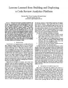
The embedded software of the underlying X-ray systems is deployed on a number of fully concurrent subsystems, of which two are of interest for this work: the BackEnd and the FrontEnd subsystems, see Figure 3. We briefly explain these subsystems to the extent required for this article. The BackEnd subsystem hosts a graphical user interface, which allows clinical users to view patients’ X-ray images, and to manage their data and exam details. It also houses predefined X-ray settings and clinical applications required to configure the FrontEnd for various X-ray examinations. The BackEnd controls the flow of events required for acquiring X-ray images with the FrontEnd through a workflow protocol.
BackEnd subsystem
FrontEnd subsystem FEClient unit
BackEnd units
C# Interfaces
FEClient state machine
ASD interfaces
BEFE Interface
Components developed manually
Fig. 3. Deployment of the FEClient in BackEnd
The FrontEnd subsystem is responsible for controlling motorized movements of movable parts, such as the table where patients can lay and the stands that holds X-ray collimators and image detectors. The FrontEnd subsystem is also responsible for calibrating these components upon requests sent remotely by the BackEnd subsystem, according to the predefined X-ray settings. Once all components are prepared, the FrontEnd subsystem requests the BackEnd subsystem to prepare its internal components, and asks permission to acquire images.
7
Upon obtaining permission, the FrontEnd starts acquiring X-ray images. The images are then viewed on the graphical interface of the BackEnd and locally stored for future potential references. The BackEnd subsystem comprises a total of 12 distinct software units, three of which incorporate the ASD technology for developing their control parts. One of the key units is the FEClient, which mainly mediates messages between various units of the BackEnd and the FrontEnd subsystem across a physical network. The interaction between the two subsystems is standardized by a predefined communication protocol, specified by an ASD interface model, called the BEFE interface; see the deployment of the FEClient in Figure 3. The interaction between the two subsystems is rather complex, and the architecture depicted in Figure 3 is prone to various kinds of deadlocks, raceconditions and failures. Any of the following components may fail during the execution of the system: any unit of the BackEnd; the FrontEnd subsystem; the network connection between the FrontEnd and the BackEnd subsystems. For example, if the BackEnd loses its connection to the FrontEnd subsystem, the problem may be that the FrontEnd subsystem has a major failure, or that there is a network outage between the two subsystems. In either case the failure may be temporarily or persistent. The FEClient knows whether the FrontEnd subsystem is at fault, and therefore must correctly respond to internal BackEnd requests, by providing proper handlings: viewing of patients’ images and data, regardless of the presence or absence of the FrontEnd subsystem, for instance. Once the source of failure has disappeared, the FEClient must ensure that both subsystems are synchronized back to a predefined state. Briefly, the FEClient provides numerous benefits such as: - manipulation of data in readable formats comprehended to communicating subsystems, - guaranteeing the consistency of states between the external subsystems and internal BackEnd units, - exchanging of patients’ data and exams, constructed and originated by BackEnd units, and sent towards the FrontEnd subsystem, - processing of X-ray settings, constructed and exchanged by the BackEnd and the FrontEnd subsystems, - and handling the requests for acquiring X-ray images from the FrontEnd subsystem. The FEClient includes a complex control part (a state machine), which maintains the current state of the system, and enables units on BackEnd to correctly communicate with the FronEnd and vice versa. The control part comprises a total of 88 different stimuli, 211 responses and 26 distinct states. The impetus of the FEClient state machine was the need of safeguarding the flow of information between the fully concurrent subsystems, by preventing potential deadlocks, livelocks, race conditions, and illegal interactions. Due to the distributed nature of the system, each component has only partial information about the state of the system, raising the complexity of providing correct interactions among the concurrent, interacting parties.
8
Therefore, the ASD technology was used to develop the control part of the FEClient unit, and the external interfaces of the components on the boundary. Initially the ASD technology was utilized to formally specify the protocol of interaction between the FrontEnd and the BackEnd subsystems, by means of the BEFE interface, to provide equal understanding of the protocol among separate teams developing the subsystems. At later stages, the interface model was used not only as a formal documentation but also for the formal verification of the FEClient state machine.
4
The application of ASD for developing the FEClient
We report about the activities conducted for developing the FEClient, starting from January 2008 till the end of 2010. Development of the FEClient involved 3 full-time and 1 part-time team members. All had sufficient programming skills, but limited background in formal methods. The team had been exposed to ASD training courses, to learn the fundamentals of the method and its technologies. The ASD method required a learning curve because it was new to the development team. Therefore, time, investments and experience were required before developers became skilled in the technology. At the beginning of incorporating ASD to the development of FEClient, two ASD consultants were present, who devoted roughly half of their time to the project, helping developers to rapidly learn the technology and its practices. The unit was developed in a small team to afford greater quality and control, compared to larger teams or individuals.
Requirements
Incremental Software planning design
Functional specification
Behavioral verification
Specification review
Code generation
Code integration
Testing
End of increment
Fig. 4. The ASD processes in a development increment
The FEClient was developed in a pipeline of consecutive increments. The control part of the FEClient was fully implemented using the ASD method, whereas the data or computation parts were developed using the conventional development method. The traditional development process was adapted to fit the ASD method; see Figure 4 which depicts the flow of processes with respect to ASD in a development increment. Table 1 briefly describes these processes plus the percentage of time conducted for developing the control part of the FEClient throughout all of its increments. Requirements and incremental planning. To ensure that the development team clearly understands the essential functions of the system before development
9 Table 1. Time and activities of developing FEClient 5% Incremental planning 10% Software design
25% Functional specification 24% Model checking
5% Specification review 10% Code generation and integration 20% Testing 1% End of increment
Formation of teams and their responsibilities; work breakdown estimation for each function including time, efforts, deadlines, risks, etc. for each planned function Decomposition of the unit into ASD and manually developed components; assigning responsibilities to components; adapting design to new planned functions Specifying the external behavior of the FEClient towards its clients; describing the ASD design model of FEC; specifying the interface models of the used components Searching for deadlocks, livelocks, illegal calls; detecting race conditions and violation of protocol of interactions; formally check the refinement correctness of FEClient internal implementation against its external specification Team review of interface specifications for all specified rulecases; checking traceability to informal requirements; checking naming consistencies Generating code in C# language; integrating the generated code to the system; implementing glue code Unit test of generated and manually written code; function and coverage test for manually written code Problems solving; bug fixing
activities begin, Philips chose to formally express the requirements of the system in tags using CaliberRM, a software requirements management tool. To increase their awareness even more, the development team is required to reference the tags in the specification of ASD models. As soon as the requirements of FEClient had been clarified, the planning of implementing a subset of predefined functions was established, with work breakdown estimations and a tight schedule. FEClient design. On completion of incremental planning, the design of FEClient components started as working drafts, reviewed by team members in a number of sessions. Feedback from each team review session was incorporated to further improve the informal designs. Team reviews provided opportunities for code economy by identifying reusable modules (or common services) such as tracing and logging. At the end of the design step the distribution of components was accomplished, with well-defined interfaces and responsibilities. The effort of obtaining an appropriate design that fits the ASD specification and verification style was higher than normal since the technology does not support all design or architectural patterns, with which the developers were acquainted. For example, not all object-oriented design patterns [5] can be easily modeled using the ASD ModelBuilder, and that all ASD components must be structured in strict levels. The ASD components must be designed in a component-based action-oriented manner.
10
Functional specification. After the design step was accomplished, fourteen ASD interface models that capture the external behavior of the FEClient state machine component and the internally used components were described using the ASD ModelBuilder. The structure of the ASD components of the FEClient is depicted in Figure 5. The FEClient state machine was described using an ASD design model, implementing both the external behavior towards the clients and the internal behavior of the FEClient towards the internal components and towards the FrontEnd subsystem. The development of the manually coded modules was done in parallel to the ASD modeling. The specification process of the ASD models was a straightforward but tenacious activity. It enforced the user to think carefully about every possible scenario, leading to an increase in the quality of requirements and to stimulate early discussions with stakeholders for clarifying ambiguous scenarios. The completeness of specification imposed by the technology caused some models to suffer from being over-specified and being difficult to understand and maintain, until special filtering features were supported by the ModelBuilder. Behavioral verification. After all models were specified, the formal behavioral verification process using model checking was started. Race conditions, deadlocks, livelocks, and illegal scenarios violating the communication protocols were discovered early, causing either to adapt the specification or to redesign the components of the FEClient. The verification of the FEClient included the interface model of the BEFE interface. The communication protocol specified in the early BEFE interface model contained some errors discovered during the behavioral verification and specification reviews. Such errors were communicated to the team involved in the development of the interface. It is notable that the state space explosion problem kicked in during the verification sessions. Since developers could not proceed to code generation without the behavioral verification, the design was adapted to circumvent the problem. Various communication styles that cause this problem were avoided to make verification achievable [7, 6]. Although model checking contributed substantially to the quality of the FEClient, it imposed additional efforts to deal with race conditions that can hardly happen in practice. Specification review. When the behavioral verification process had been completed, specification reviews of ASD models were conducted to verify completeness, correctness, and traceability to the original tagged requirements. Participants in review sessions varied, but always included the owner of the specification and one or more persons who had previously been trained in ASD. In general it was difficult for non ASD users to follow the review process. The early lack of compare and merge functionality in the ModelBuilder complicate the review process further. Reviews were performed in a number of sessions of roughly half an hour each, and documented in dedicated separate review sheets. Code generation and code integration. Once specification reviews were accomplished, the models were automatically translated into the target language, in
11
Upper level clients of FEClient
IFECSM FECSM
13
1
IVersion
ITracing
Manually coded components
IBEFE FE subsystem
Fig. 5. The structure of the FEClient
this case, C#. The generated code was integrated with the manually written code by implementing glues of appropriate adapter and wrapper code. The integration process of the FEClient generated code with the generated code of other ASD components was remarkably smooth. The interface model of the FEClient is used by 5 fully concurrent ASD client components, which use the interface model for the behavioral verification, according to the ASD recipe. Consequently only one error had been reported (detailed in the subsequent section) during the integration of the FEClient generated code with the code of the ASD client components. This compares favorably to the traditional development methods where integrating concurrent components poses substantial efforts to fix potential errors, and to bring components to work together correctly. FEClient test. The ASD generated code was not a target of function coverage or statement coverage tests, which applies to the manually developed code. Unit testing was started after the generated code was integrated with the manually written code. The FEClient state machine always passed its unit test, and only few errors were discovered during system test. During the construction of the FEClient few errors had been committed; fixing these errors often commenced at the end of each increment. We discuss these errors in subsequent section. The total number of hours spent for specifying and verifying ASD models plus generating and integrating code of all the FEClient increments was nearly 700 hours. Table 2 depicts statistical data of the FEClient state machine and the interface models of the used components. The first column lists the names of the ASD models, from which code was generated and correctness verification was checked. The second column reports the total number of rule cases, specified and reviewed by team members. The third, fourth and fifth columns demonstrate statistical outputs for checking deadlock
12 Table 2. The ASD models of the FEClient Model
Rule States Transitions Time Total Executable cases (sec) LOC LOC FECSM 2376 1,996,830 5,249,538 230 11,159 11,121 IFECSM 1,068 3,028 7,112 0 208 173 IBEFE 2,183 931 8,537 0 144 129 ICTFFacade 51 6 28 0 107 70 IConfigRepository 8 2 7 0 90 53 IDataServiceFactory 8 4 4 0 86 49 IEnumConversions 16 2 15 0 98 61 IParameters 18 7 22 0 125 88 IParameterCache 4 2 3 0 86 49 IPerformance 5 2 4 0 87 50 IReportLogging 3 2 2 0 85 48 IRunTag 12 15 33 0 90 53 ISystemType 4 3 4 0 85 48 ITracing 3 2 2 0 85 48 IUserGuidance 16 18 64 0 102 65 IVersionExchange 4 3 4 0 85 48 ASD run-time 803 701
freedom using the model checker FDR: the generated states, the generated transitions and the time in seconds required for verification respectively. All models are deadlock free. The last two columns depict the generated lines of code (LOC), in the C# programming language. The total LOC denotes all source lines, including blank and comment lines. The executable LOC includes all executable source lines of code excluding blank and comment lines. The IFECSM model is the interface model that captures the external behavior of the FEClient unit. As mentioned earlier, this model is used by other ASD clients located at other units of BackEnd, to formally guarantee the interaction correctness among the units. As can be seen from the table the model comprises a substantial number of specified rule cases. This directly affected the description of the FEClient design model (FECSM), which is clearly the most complex model among all others. The reason of this complexity is that ASD allows only one design model for refining any interface model, which means that a decomposition of an interface model to a number of simple design models is not supported at the moment of writing this article. The behavioral verification of all ASD models was conducted by a remote server with secure connections, controlled by Verum, the ASD company. The verification of all interface models were accomplished separately, except for the state machine, which was verified as a combined model that includes the state machine design plus all interface models of used components. As can be inferred from the table roughly 8.5 thousand states can be generated per second by FDR, but this number was not constant for all remote verification sessions of the state machine. In some circumstances the remote verification process was slow, and
13
the ASD users were forced to wait longer until verification results appeared on their screens.
5
Quality results of the FEClient unit
The FEClient development team prepared careful reports of all errors found during the construction of the unit. The unveiled defects were committed to a bug tracking system, which is part of a sophisticated code management system. The feedbacks and comments from the project leaders were very positive, and the unit appeared to be stable and reliable. But the project leaders wanted to know more about whether the use of formal methods affected the quality of the code. For scrutiny purposes, Philips opened their error reports, and we carefully investigated them trying to determine the impact of formal methods on the quality of the code. Our analysis reveals the followings. A total of eleven errors related to both ASD and the manually written code were reported along the construction of the unit. Four errors were found during implementation, five during integration, and two during system testing. Three of the eleven errors were caused by design, e.g., missing a response to a test component in the ASD state machine; and eight errors introduced during implementation, e.g., a redundant “WARNING” word in some traces, which complicated the analysis of other traces. Of the eleven errors, four would have caused failures during system execution. One of the four errors is severe and most likely to occur, e.g., misspellings in data could cause a crash at the FrontEnd subsystem. One error is average with low probability of occurrence, e.g., a race condition between a request to acquire images from the FrontEnd subsystem and a request to exchange X-ray settings from BackEnd clients. The remaining two are minor errors, e.g., a crash due to a failure to load a missing dll file during version exchange with the FrontEnd subsystem.
Activation of an external component Activation of internal components
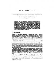
Fig. 6. The order of activating boundary components caused an error
14
Figure 6 depicts a specification of a rule case that caused an unintended behavior of the system, during the integration phase in one of the project increments, due to a wrong order in the responses list. The rule case specifies that when the FrontEnd subsystem is activated, it sends the Activated event to the BackEnd via the BEFE callback interface; this is indicated by the channel and the stimulus event of the rule case. Upon receiving the Activated event, the FEClient sequentially executes a list of responses, each until completion. The order of the depicted responses was not correct since one concurrent external client component was activated before the internal components of the FEClient. The order was initially made this way to shorten the time required for activating BackEnd units. But, if the client component was quick, it could send events to the internal components which were not activated yet. The consequence was that the user interface, on the screen of the BackEnd, shows an indication that acquiring images is not possible, while it should be. Due to the concurrent nature of the client component, the error was hard to reproduce manually, but locating the source of the error was easy. Correcting the activation order, such that the external client is activated after the internal components, was straightforward, and indeed solved the issue. In general, the errors reported during the development of the FEClient are simple goofs, easily found and fixed, and not critical design or interface errors. A summary of these errors is given in Table 3. We use the error categories defined by Basili and Selby in [1]. The error severity codes are as follows. M Major error, N Minor error, V Average error, H High probability of occurrence, L Low probability of occurrence, F Error would have cause a failure during system execution. Four extra codes specify whether the error was caused/found during design (“D”), implementation (“I”), integration (“G”) or system testing (“T”). The development activities of the manually written code yield 15,462 lines of executable code, with a rate of 0.52 defects per KLOC. The total number of ASD generated code is 12,854 lines of executable code, which report 0.23 defects per KLOC. Clearly, the quality of ASD and the manually written code are comparable, but the quality of ASD code appears to be better. The complete unit exposes an average of 0.4 defects per KLOC. This level of quality compares favorably to the standard of 1-25 defects per KLOC for traditionally developed software in industrial settings [10]. The quality of the ASD developed code depends on many things, including specification reviews and the formal behavioral verification. Model checking covered all potential scenarios, and defects were found early and quickly with the click of a button. The quality of the manually developed code depends on many factors, including the external specification of components, strict code reviews and thorough testing. Developers of the unit were committed to 100 percent function coverage
15 Table 3. Summary of errors found during the construction of the FEClient unit Category
Error Caused ASD Description of error severity /Found Control V/L/F D/I Yes Race condition between exchanging X-ray settings and a request to acquiring X-ray images V D/T Yes Missing a response to test component in a rule case M/L D/G Yes Not possible to generate images although it should be possible Data V I/G No Test interface is exposed in deployment environment M/H/F I/G No Misspelling in DataDictionary caused exception at the FE subsystem V/L I/G No Image Acquisition indicator is not enabled Initialization N/L/F I/T No Missing configuration file caused exception in test system at startup V/L/F I/G No Exception when version exchange assembly loading fails External V I/I No Tracing shows up in logging database V I/I No Coding standard violation Cosmetic N I/I No Redundant WARNING word in tracing Computation - No errors Interface - No errors
and 80 percent statement coverage. The team had tracked coverage testing using the NCover tool, which reports the percentage of functions and statements covered by sets of tests. The total number of test code written for FEClient unit test is 10,943 lines of executable code. For the FEClient case, it appeared to us that code review was far more effective than coverage testing, and that more issues had been found during review than in testing. But unit testing had major benefits of detecting memory leaks, optimize memory usage and provide a proper framework for code coverage. Team members appreciated the ultimate quality of the FEClient software. The behavioral verification and the firm specification and code reviews provided a suitable framework for increasing the quality, assisting the work, and decreasing potential efforts devoted to bug fixing at later stages of the project. Acknowledgements. We would like to thank Marco van der Wijst for his substantial efforts of developing the FEClient at earlier stages. We wish to thank Tom Fransen, Amol Kakhandki and Marco van der Wijst for their useful comments on the text.
16
References 1. V. R. Basili and R. W. Selby. Comparing the effectiveness of software testing strategies. IEEE Trans. Softw. Eng., 13:1278–1296, December 1987. 2. G. H. Broadfoot. ASD case notes: Costs and benefits of applying formal methods to industrial control software. In FM 2005: Formal Methods, volume 3582 of LNCS, pages 548–551. Springer (2005), 2005. 3. I. Crnkovic. Building Reliable Component-Based Software Systems. Artech House, Inc., 2002. 4. FDR homepage. http://www.fsel.com, 2011. 5. E. Gamma, R. Helm, R. Johnson, and J. Vlissides. Design patterns: elements of reusable object-oriented software. Addison-Wesley Professional, 1995. 6. J. F. Groote, T. W. D. M. Kouters, and A. A. H. Osaiweran. Specifcation guidelines to avoid the state space explosion problem. CS-Report 10-14, Eindhoven University of Technology, 2010. 7. J. F. Groote, T. W. D. M. Kouters, and A. A. H. Osaiweran. Specifcation guidelines to avoid the state space explosion problem. In Proceedings of the 4th IPM international Conference, FSEN 2011, page (IN PRESS), Theran, Iran, 2011. SpringerVerlag, Berlin, Germany. 8. J. F. Groote, A. A. H. Osaiweran, and J. Wesselius. Benefits of applying formal methods to industrial control software. CS-Report 11-04, Eindhoven University of Technology, 2011. 9. P. J. Hopcroft and G. H. Broadfoot. Combining the box structure development method and CSP for software development. Electr. Notes Theor. Comput. Sci., 128(6):127–144, 2005. 10. S. McConnell. Code Complete, Second Edition. Microsoft Press, Redmond, WA, USA, 2004. 11. S. J. Prowell and J. H. Poore. Foundations of sequence-based software specification. IEEE Transactions on Software Engineering, 29(5):417–429, 2003. 12. A. W. Roscoe. The theory and practice of concurrency. Prentice Hall, 1998. 13. Verum homepage. http://www.verum.com, 2011.