Resistor Color Code Guide. Note: I took this chart off of the web. In my experience
, the tolerance band is NOT usually separated from the other bands as shown ...
Military Solderable Leads. 0. 1. SIG. NIFICANT FIGURES. 2. 3. 4. 5. 6. 7. 8. 9. 10
%. 5 %. 1 %. RESISTOR COLOR CODE CHART. 1st SIGNIFICANT. FIGURE. 1.
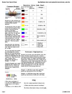
The Resistor Color Code. Resistor values are normally shown using colored
bands. Each color represents a number as shown in the table. Most resistors
show ...
RESISTOR COLOR CODE. The sequence of colors can be easily remembered
by the little. Rhyme I learned in school one day! Here it is for what it's worth!
MELF and Leaded Resistor Products – E96 Series and E192 Series. Band 2.
Coding. Band 1. Coding. Band 3. Coding. Band 4. Coding. Band 5. Coding.
Resistor Colour Code. Aim: - To study the system of colour coding which is used
to indicate the resistance value of carbon resistors. To measure the resistances ...
Experiment 1 — Resistor Color Code and Use of the. Ohmmeter. EL 111 - DC
Fundamentals. By: Walter Banzhaf, E.K. Smith, and Winfield Young. University of
...
Resistor color coding system applies to carbon film resistors, metal oxide film ...
The first 3 (4) bands closest to one end of the resistor are used to determine the ...
9 Nov 2002 ... Common Resistor. Resistors are color coded for easy reading. Imagine how
many blind technicians there would be otherwise. To determine ...
John Riley, Robert Gidge, George. Postell, Virgil. Rabine, Dave Pierce, Evan Webb and John Degnan for their many contributions towards the completion.
International Business Machines Corp., Poughkeepsie, N. Y.. Methods of analyzing .... points to a list of all blocks that could be executed im- mediately after the ...
The modular verification of object-oriented code is made difficult by the presence
... software engineering principle of modular programming be- comes crucial: it
brings ... order separation logic techniques do not hide shared data. When using
...
an amodal or modality-independent format. Another issue ..... BMLwalker.html). AC's ability to discriminate .... As a follow-up (June 2013) AC was given the longer online version ... Photoshop), and next to the target stimulus were two choices.
Mar 8, 2001 - Keywords: histogram indexing, quantization, object recognition, color cat- .... Welch's Grape Drink, C = Coca-Cola, D7=Diet 7-Up, CD = Canada ...
What can the board learn from the composition of competitors' boards? .....
Process Management (BPM) across multiple applications, corporate ..... doing
business www.think2ool.com/think2ool_files/ChinaDownload.pdf downloads ......
What software sy
British Wiring Color Code. 1. Color Combination. Application. Black (B) Always
Earth. (ground), un-fused. Black (B). Various Locations. Black/green. URP switch
...
A color term is any single word used to create a color name. A substring ... World. Wide Web. JavaScript. HTML. FormMail e-mail. Responses. Observer. Display.
University of Technology. Laser and Optoelectronics Engineering Department.
DC circuits analysis laboratory 2011-2012. Experiment No.1. Resistor Color
Code.
University of Technology Laser and Optoelectronics Engineering Department DC circuits analysis laboratory 2011-2012
Experiment No.1 Resistor Color Code Object 1. To learn Resistor Color Code 2. To determine the stated value of a resistor by interpreting the color code indicated on the resistor.
Apparatus 1. Set of wires. 2. Carbon Resistors. 3. Digital A.V.O. meter.
Theory There are two ways to find the resistance value of a resistor. The color bands on the body of the resistor tell how much resistance it has. As shown in the following diagrams figure (1), there are 5-band resistors and 4-band resistors. Form both 5- and 4-band resistors, the last band indicates tolerance in table (1). Consult with the “Resistor Tolerance” in table (2) chart for finding the tolerance value.
Fig.( 1) 5- Band and 4- Band resistors
1
University of Technology Laser and Optoelectronics Engineering Department DC circuits analysis laboratory 2011-2012
The first method for read resistor colors in Fig.(2)
Fig.(2) First method read resistor
2
University of Technology Laser and Optoelectronics Engineering Department Table(1) Readlaboratory resistor color DC circuits analysis 2011-2012
The first litter word to represent color resistor code in table (1)
Table (2) Resistor Tolerance View the resistors and based on the color bands determine its value. Below is an example:
The first band is a one (1), the second band is a zero (0), and the multiplier band or third band is one time text to the third power ( ) or one thousand (1000). Multiply 10 times 1000. Another way to tell the resistance value of a resistor is to actually measure it with the ohmmeter. The explanation of how to measure the resistance is given in the later tip. Where:Rmax = R+(R * T ) 3
University of Technology Laser and Optoelectronics Engineering Department Rmin = R+(R * TDC ) circuits analysis laboratory 2011-2012
Procedure 1. Measure and record twenty resistors with value of 1 Kohm. 2. Find the R max. , R min. then calculate the percentage error. 3. Repeat the steps (1,2) with resistor value of 10K ohm. 4. Repeat the steps (1,2) with resistor value of 100K ohm.
Discussion 1. Comment for your results. 2. Determine the value and tolerance of the 10 resistors as shown in the following tables for chart fig. (3):
4
University of Technology Laser and Optoelectronics Engineering Department DC circuits analysis laboratory 2011-2012
5
University of Technology Laser and Optoelectronics Engineering Department DC circuits analysis laboratory 2011-2012
Fig.(3) 3. Record resistor colors gave to its value in below : 4.7 KΩ 5% , 910Ω
, 12 Ω 6
5%,
6.8KΩ
20%
University of Technology Laser and Optoelectronics Engineering Department 4. Is there difference between percentage errors of 2011-2012 three resistors (1K, DC circuits analysis laboratory