University of Iowa, Iowa City , Iowa 52242, U.S.A.) ... (Department of Physics and Engineering Science, Loras College, Dubuque, Iowa ... ZUSAMMENFASSUNG.
Journal 0/ Glaciology, Vo!. 32, No. 112, 1986
EXPERIMENTS ON FREEZE-BONDING BETWEEN ICE BLOCKS IN FLOATING ICE RUBBLE
By R. ETIEMA (Iowa Institute of Hydraulic
Research,
Department of Civil and Environmental Engineering,
Un ive rsit y of Iowa, Iowa Ci ty , Iowa 52242,
U.S.A.)
and J.A. SCHAEFER
(Department
of Physics and Engineering Science, Loras College, Dubuque, Iowa 52001, U.S.A.)
ABSTRACT. Series of experiments were conducted with the aim of determining the influences of the following factors on freeze-bonding between contacting ice blocks in floating ice rubble: pressure normal to the contact plane, period and area of contact, and salinity of the water in which freeze-bonding occurred. Freeze-bonding between ice blocks in air was also investigated. The experiments were · conducted with water and air temperatures of about O C and normal pressures, between ice blocks, up to 4 kPa. This range of normal pressures may occur hydrostatically between ice blocks in layers of floating ice rubble up to about 10 m thick, or in 2-3 m thick layers which are in a passive Rankine state of pressure. The experiments show that stronger freeze-bonds develop between ice blocks in distilled water, tap water, and water from the Iowa River than · develop between ice blocks contacting in air at O C. · However, stronger freeze-bonds developed in air at O C · than developed between ice blocks in O C saline (NaCI) solutions with salinities in excess of 12.5% by weight. The strength of freeze-bonding increased linearly with contact period for ice blocks in distilled, tap, and river waters, but did not increase with contact period for ice blocks contacting in saline solutions or in air. The results of the experiments are useful contributions to explanations of the shear-strength behavior of a layer of floating ice rubble. For example, thicker layers of ice rubble may show greater cohesive behavior, because normal pressures and thus freeze bond strengths increase with layer thickness. RESUME. Experimentations sur l'agregation par regel entre blocs dans la blocaille de glace [lollan/e. Des series d'experiences ont ete menees dans le but de determiner I'influence des facteurs suivants sur I'agregation par regel entre les blocs en contact dans la blocaille de la glace f1ottante: pression normale sur le plan de contact, dUflle et surface de contact et salinite de I'eau dans laquelle se produit ce collage par rege!. L'agregation par regel entre les blocs dans I'air a aussie ete examinee. Les experiences ont eu lieu avec des temperatures de I'eau et de I'air voisines · de O C et des pressions normales entre blocs, superieures a 4 kPa. Ce domaine de pressions normales peut exister entre les blocs disposes en couches dans la blocaille de glace f10ttante sur des hauteurs de 10 m d'epaisseur ou sur des couches de 2 a 3 m qui se trouvent en etat de pression passive de Rankine. Ces experiences montrent qu'un collage par regel se developpe plus intensement entre blocs places dans de I'eau distillee, de I'eau du robinet, et de I'eau
INTRODUCTION Laboratory studies (e.g. by Uzuner (1974), Tatinclaux and Cheng (1978), and more recently by Hellman (1984)) show that the shear strength and deformation behavior of a relatively thick (block size being small compared to layer thickness) layer of floating ice rubble may be described using a Mohr--coulomb relationship involving a term for apparent cohesion. Additionally, these studies show that
provenant de la Iowa River, qu'il ne se developpe entre · blocs en contact dans I'air a O C. Cependant une agnlgation . se developpe plus intensement dans I'air a 0 C qu'elIe ne le fait a 0 C avec des blocs en presence de solutions salines (NaCI) pour des salinites superieures a 12,5% e n poids. La solidite du soudage par regel crott lineairement avec la duree du contact en eau distillee, de robinet et de riviere, par contre elIe ne crot! pas en fonction d u temps de contact pour des blocs places dans une solution saline ou dans I'air. Les resultats de ces experimentations constituent une contribution utile a I'explication du comportement resistant de la couche de glace flottante en blocs. Par exemple des couches de glaces de blocaille plus epaisses peuvent presenter un comportement plus cohesif, par suite des pressions n ormales et de la des resistances de soudages qui augmentent avec I'epaisseur de la couche. ZUSAMMENFASSUNG. Versuche zum Zusammen/rieren von Versuchsreihen Eisschutt. schwimmenden im Eisblocken wurden angestellt mit dem Ziel, den Einfluss der folgenden Faktoren auf das Zusammenfrieren von sich beriihrenden b estimmen: Eisschutt zu schwimmendem in Eisblocken Normaldruck an den KontaktfHichen, Dauer und FHiche des Kontaktes, Salzgehalt des Wassers, in dem der Gefrier vorgang stattfindet. Zusammenfrieren von EisbWcken in Luft wurde ebenfalls untersucht. Die Versuche wurden bei · Wasser- und Lufttemperaturen von etwa O C und unter Normaldruck bis zu 4 kPa zwischen den Eisblocken durch hydrostatisch Normaldruckbereich diirfte Dieser gefiihrt. zwischen Eisblocken in Schichten schwimmenden Eisschuttes bis 1 0 m Dicke oder in 2-3 m dicken Schichten, die sich in einem passiven Rankine-Druckzustand befinden, auftreten. Die Versuche zeigen, dass sich sHirkere Frostbindungen zwischen Eisblocken in destilliertem Wasser, Leitungswasser und Wasser aus dem Iowa River bilden als zwischen Eis · blocken in Luft bei 0 C. Doch entwickeln sich sHirkere · Frostbindungen in Luft bei O C als zwischen Blocken in · Salzlosungen (NaCI) bei O C mit einem Salzgehalt von mehr als 12, 5 Gewichtsprozent. Die Starke der Frostbindung Eisblocke in der Kontaktzeit fiir mit wuchs linear destilliertem, Leitungs- und Flusswasser, jedoch nicht bei Eisblocken in Salzl()sungen oder Luft. Die Versuchsergebnisse sind ein niitzlicher Beitrag fiir die ErkUirung des Verhaltens der Scherfestigkeit einer Schicht schwimmenden Eisschuttes. So konnem z.B. dickere Schichten eine grossere Kohasion aufweisen, weil der Normaldruck und damit die Starke der Frostbindung mit der Schichtdicke zunimmt.
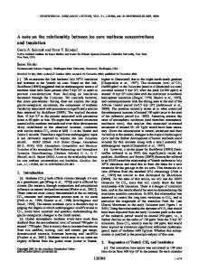
shear-rate strongly affects the shear strength of a layer of ice rubble. One explanation for the cohesive behavior of a layer of floating ice rubble, and for the effect of shear-rate on shear strength, is the development of freeze-bonds between adjoining, contacting ice blocks. Consider t w o ice blocks, both with side dimensions of unity, brought in contact as illustrated in Figure I . If the blocks are loaded with a normal force which produces a normal pressure cr, then subsequent to a period t after 397
Journal of Glaciology packing of ice blocks, Additionally, c will be influenced by
AIR/ WATER
the temperature and salinity of the water in which the layer of ice rubble floats, Understanding
the
nature
of
freeze-bonding
between
ice blocks is important for understanding the shear-strength and deformation behavior of a floating layer of ice rubble. Surprisingly
T T
A,l .Jh W'
little
is
�
about
the
intrinsic
cohesion
and there have apparently been
block
c onsiderable number of studies (e.g.
investigations on the
ICE BLOCK
known
between blocks of ice,
by
o n ice block.
Oksanen, 1983)
strength of bond
A
have
been conducted
to
strength of ice bonding to other materials. Merino
(1980),
(1974),
and others
of the
Uzuner
have
and
no
formed between
Kennedy
shown that the
determine
(1976),
ice
the
MelIor
vertical component
internal stresses with a layer of floating ice rubble
can be written as
Fig. 1. Contact between two ice blocks. 0,
application of
at
their
the two blocks would have to be separated
interface T
shear stress
be separated,
(2a)
by
a
across
T
shearing
force
which
produces
a
the bond, In order for the blocks
and
to
of a freeze-bond between the blocks. of
The aim of
this
freeze-bond
study is to determine the dependence T
strength
on normal
0,
pressure
contact
time t, fluid - air, pure water, or saline water - surround
ing
the
two
ice
blocks,
the
range of pressures
and
contact
area. The
range
of
normal pressures was limited to a maximum value of 4 kPa, averaged over the nominal contact area. This value is within rubble
up
state.
to
about
The
that may
9m
thick
develop in layers
and
temperature
in
of
a
neutral
the
water - surrounding the blocks was held at 00 C.
of
ice
Rankine
fluid - air,
after
the
its
nature
of
formation,
undergoing
a
deformation
granular
medium.
between
ice
mechanical
which p is porosity of the layer, P i and P are the w densities of the ice blocks and water, respectively, his total thickness
of layer
of
ice
rubble, and z
is
distance below
the top surface of ice-rubble layer. Equations (2a) and (2b) express
average
floating
rubble.
higher.
stress
Locally,
at
any
level through
contact stresses
may
a
layer
of
be somewhat
Figure 2 depicts a simplified layer of ice rubble. If the
p.
Its
friction
blocks
and
ice-rubble
layer
of
behaves
shear
:
P;
WATER DENSITY
:
DENSITY OF RUBBLE ICE MASS
strength
ice
to
results
resistance,
contact.
Immediately
floating
similarly
rolling
in
strength.
For
this
a
and
rubble
deformed
from
the
cohesion
reason,
most
attempts (e.g, Keinonen and Nyman, 1978; Prodanovic,
1979;
Hellman, 1984) to date at formulating shear strength of rubble have expressed it in the form of the Mohr-Coulomb
WATER
relationship:
T
where
T=c+otan�
(1)
is the shear strength, c the
cohesive intercept,
the compressive stress normal to the shear plane, and
angle of internal resistance. As
soon
formation, other
as
adjacent
at their
the
rubble
comes
ice blocks may
points
of
contact,
start
and
to
rest
cP the
after
its
to freeze to
form a rigid
Fig. 2. Pressures within layers of floating ice rubble. 0
matrix
submerged, the surfaces of the ice blocks are at the melting temperature.
Consequently,
little or no
submerged
heat
boundaries
freezing
transfer. This
into
each
can
seemingly
begins
of
immediately
and continues so that, with the passing of time, the freeze
bonds strengthen and the shear strength of the consolidated rubble increases.
values
x
P = 0.92 i
It is important to note here that tempera
are assumed, p = 0.40, Pw = 103 kg/m3, 103 kg/m3, then Equation (2a) becomes
O
z
= 5.42z
The relationship between For
the
present study,
kPa.
As
is
regard
reason,
it
of different temperatures and sizes. It
intimate
is
extensive
evident
contact
that
any
between
surface-contact
ice
factor
area
may
be
which
blocks
will
between
difficult
leads
to
more
produce
ice
to
blocks
more
and
increase the shear strength of the layer, as well as, possibly, freeze-bond
be a function of
between the ice blocks. Therefore, 0,
T
will
not only for its role of increasing the
Oz and z is indicated in Figure 2. the development of freeze-bonds is
suggested
extrapolate the results on freeze-bond strength to ice rubble
this
(3b)
examined for compressive, or normal, pressures up to about
4
compressive pressures
For
(3a)
O z = 0.47l(h- z) ... (kPa, with hand z in m).
ture distribution through contacting ice blocks likely affects freeze-bonding,
(kPa, with z in m)
and Equation (2b) becomes
occur
freezing diffusion
other
following
each
known as consolidated rubble. Because most of the rubble is
the
(2b)
It is helpful to the understanding of the ensuing study
outline
with
I?i.h P w'
in
BACKGROUND
to
�
for z
would have to overcome the shear strength
0 ' Z
is
in
Figure
commensurate
2,
this
with
range
vertical
of
stress
acting through ice-rubble layers up to 10 m thick, With. to
rubble,
lateral
0-4
actin�
kPa
pressures is
acting
commensurate
through
through layers up to ( 10 . . . coeffIcIent of Rankme-state paSSIve
with
a
layer
passive
of
ice'
pressures
m)/ K p thick. pressure, Kp'
The
varies
from about 3 to 8 for values of angle of internal resistance
ranging
pressures range
from
30 °
used for
for
layers
to
the
of
about
50 o.
The
present study floating
ice
range
covers
of
much
rubble
normal
of
the
commonly
mechanical friction of the rubble but also because a large
0
encountered in Nature.
area and, thereby,
a
or ice particles, is well known and has been investigated by
decreases rubble
porosity,
also c.
71,
and
increases
surface
contact
The intrinsic cohesion, c,
of
layer of floating ice rubble is a function of contact period,
t, compressive pressure 398
0,
as well as shape, roughness,
and
The phenomenon of freeze-bonding between ice blocks,
such
noted
physicists
as
Michael
Faraday
and
James
Thomson. Most of research effort has been concentrated on
Ettema and Schaefer:
Freeze-bonding b etween ice blocks
investigations of freeze-bonding between suspended particles of
ice
(e.g.
Faraday,
Thomson,
1859;
especially
1861),
spheres of ice (e.g. studies by Nakaya and Matsumoto, 1954; Jensen,
1956; Kingery,
1960; Kuroiwa,
Mason, 1964).
Hobbs
1961;
and
The mechanism causing ice pieces to b e adhesive, and
hence the cohesive behavior been
the
of a layer of
topic of considerable interest
ice rubble, has
and
debate. Hobbs
(1974) and Pounder (1965), among others, provided detailed
discussions on freeze-bonding. Faraday ascribed freeze bonding to the freezing of a "liquid-like" layer (term used by
Hobbs)
Thomson
at
the
interface
attributed
of
freeze-bonding
the contact between two ice pieces. More
welding,
recently,
has
freeze-bond
pieces
for
process
used
between
surrounded
(1961),
the
been
to
air.
ice
used
ice
pressure
of
Kingery
example,
freeze-bonding.
moist
to
the
or
of
especially and
(1960)
at
cold
growth
pieces,
this
pieces.
melting
sintering,
explain
contacting
by
two
a
for
Kuroiwa
explanation
for
When two contacting ice pieces are pressed against each
other
(e.g.
into
as
play.
pressure
closer
in Fig.
If
melting
contact,
the
I), pressure melting may also come
pressure
may
cause
and the
remains
on
the
the two ice
pressure
may
cause
film of water to be squeezed from between
The
upshot
of
the
pressure
would
development of a stronger freeze-bond.
�f
the
two
moist
ice
pieces
be
are
ice
pieces
to
a
Fig. 3. Samples of the test b locks of ice.
pieces,
seat
in
sandwiched
Aluminum frames were constructed to fit over the top
of each
size
The frames
of
were
test block
of
fitted with
a
ice,
as shown
in
Figure 4.
hook which was
located at
attached
hook
the center of the front face of each test block. The experi mental set-up is illustrated in Figure 4. A light-weight, stainless
steel-strand
cable
was
to
the
and
the ice pieces.
the
more
surrounded
rapid
by
air,
Thereafter,
the
freezmg of the water film at the contact may cause the two
pieces
to
fusion
become
fused
through
the
would
diffusion
grow
to
one
principally vapor
another.
through
phase
of
proposed by Hobbs and Mason (1964). If a freeze-bond did
the
action
water,
as
t
of
was
not form between two ice blocks
TANK
�
static friction would have to be overcome in order to slid
them apart. The shear stress to overcome static friction and
separate the two blocks can be stated as
WEIGHT
ICE BLOCK AND HARNESS
(4) where value
normal
ILs is the coefficient of static friction, for which a of about 0.1 is reasonable (Hobbs, 1974), and a is pressure.
Values
of
Tf
up to
about
0.1
x
"i
4 kPa
400 Pa would be required to separate two blocks under a normal load of 4 kPa. The
strength of
the
f reeze-bond between
two smooth
ice blocks in water and in air is examined in the discussion
that follows.
Iowa Institute
of
Hydraulic Research (IIHR).
For all tests
to +1 ·C.
d
Ice blocks of repeatable size and smoothness were pro from
mains
tap
casts. Three sizes of tap
base
areas
maintained
water at
and
water
cast
the
frozen
in
smooth
aluminum
were used. The casts were filled
placed
an internal
of
three
in
air
sizes
a freezer
box
temperature of
10-3 m2, 9.03 x 10⁻³ m2, and 19.35
ice
of
blocks
x
which
was
-10 ·C. The were 4.52 x
10-3 m2, such that the relative sizes of the base areas were I : 2 : 4 (see Fig. 3).
testing
the
aluminum
mold
in
which
it
was
cast,
the
machine
voltage from which was
from
which
it
was
leveled with a heated iron,
formed.
The
For each experiment,
a
smooth
lower slab
the test block
of
top
using the method
Oksanen and Keinonen (1982). on
manner
ice 0.71 m
of
surface
was
suggested by
ice was placed
long,
0.28 m wide,
as that
used
to produce
the
test blocks
of
ice. It was grown in an aluminum container. The surface in contact
with
the
base
of
the
aluminum
container
was
exposed
to air,
during
outwards was
the growth
leveled
using
a
of
the
heated
block,
and
iron. This
leveled face was in contact with the base of the glass-sided test tank.
to a load
was
moved
upward,
the
increasing
cable
The output
the load cell was fed to a signal conditioner
c onnected to the
IIHR HPlOOO
computer.
Most
of 0.84 mm/so
A
brief
series
of
tests was
conducted with
The load cell was calibrated periodically throughout the
experiments typical
time
Figure 5.
and
was
history
used
of
to
tension
a
precision
of
in the cable
±O.IO N. A
is
shown
in
2000 r----r---.---� RUN 22P
!i.
NO LOAD, TAP WATER
1500
vi
Ul W 0: 1000 .... Ul 0: