Universitk Paris 6 - Universitk Versailles Saint-Quentin-en-Yvelines - CNRS URA 1778,. 10-12 Avenue de l'Europe, 78140 Vklizy. * Institut d'Electronique et de ...
Proceedings of the 2000 IEEE/RSJ International Conference on Intelligent Robots and Systems
Experiments on micromanipulation using adhesion forces in unconstrained environment Y. Rollot, S. Regnier, S. Haliyo, L. Buchaillot*, J.C. Guinot and P. Bidaud Laboratoire de Robotique de Paris, Universitk Paris 6 - Universitk Versailles Saint-Quentin-en-Yvelines - CNRS URA 1778, 10-12 Avenue de l’Europe, 78140 Vklizy * Institut d’Electronique et de Micro-klectronique du Nord, Dpt ISEN, Silicon Microsystems Citk scientifique - Avenue Poincark - B P 69, 59652 Villeneuve d’Ascq cedex Abstract In this paper, we propose an original design for a manipulation system of rigid micro-objects by adhe200 p m ) in open air. The design is sion (50 p m based on a precise analysis of the mechanical conditions for manipulation by adhesion. Simulations using a dynamic m.odel of a canonical manipulation (capture and release of micro-objects) have shown that it exists an end- effect or in it ial acceleration” win dows f o r which manipulations are possible. The end-effector we have developed integrates a highly sensitive contact sensor and two piezo-accelerators (- 1Q6 m . ~ - ~Suc). cessful m,anipulations by adhesion of silicon chips with a gold coated piezoresistive silicon cantilever have been carried out and are presented as conclusion of this paper.
-
1
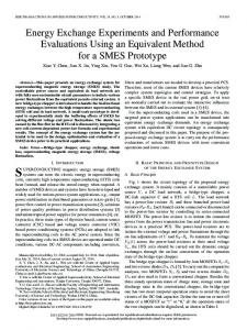
forces. What happens generally is that objects sticks to the gripper (adhesion related to the scale) (fig. 1a ) . Conversely, a second approach considers adhesion forces in the design by minimising them using appropriated coatings [l] or physical effects of higher magnitude (e.g. suction [a]). A third one proposes to use adhesion forces for the manipulation, usually in a controled environment (e.g. vacuum under a SEM) [3] [4]. The control of the environment allows the predominacy of one class of adhesion forces and make the manipulation possible (e.g. electrostatic forces for SEM). Generally the manipulation mechanisms are not simple to explain (fig. 1-b). In the above approaches, sticking effect are an handicap. The last approach consists in scaling up nanomanipulation techniques. The major problem is that the acting forces are different a t microscale, and the transition is not trivial.
Introduction
Miniaturization of systems and components leads to an increase in micro-objects manipulation needs. The design of micromanipulation systems require a precise knowledge and control of physical-chemistry and micro-tribology phenomena between surfaces involved. At microscale, between micro-objects separated with distances from 0.4 to 150nm, surface forces are predominant and volumic forces (e.g. weight) can be neglected compared t o adhesion forces. Consequently, they have a major incidence in the manipulation of micro-objects. Four main approaches have been used for the design of manipulation systems. A first approach consists in scaling down grippers and making use of grasping
Figure 1: Example of tool and realization The proposed approach consists in considering directly the micromanipulation a t the microscale and to use adhesion forces for manipulation in open air to achieve micro-manipulations solely based on adhesion forces. Three main sticking effects (Van der Waals, electrostatic, capillary) have been investigated. The manipulation problem we considered consists in picking up micro-spherical particles located on a substrate and to align them on the same substrate, this in atmospheric environment. Starting from a static analysis,
-653 0-7803-6348-5/00/$10.0002000 IEEE.
we established basic conditions (surface geometries, materials, etc.) to satisfy for a manipulation by adhesion. Dynamic models of the micro-manipulation have been built [5] and were used to analyze micromanipulations trajectories and performances, and to design the system. Successful manipulation of silicon chips of 50 200 p m under optical microscope using a single tool for capture and release are presented as conclusion.
-
2
Van der Waals forces depend on materials and object geometries. The expressions of the force also depend upon the material via the Hamaker constant A. When manipulation is done in a wet environment, capillary condensation of water appears around surface contact sites. Water intervenes in the interfaces, lowering Hamaker constants and VdW forces. For ideal geometries, Van der Waals forces are expressed by :
Static analysis
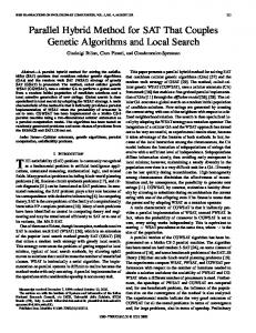
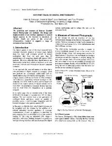
Van der Waals (VdW) forces are always present while surfaces are interacting. Their magnitude depends on the geometry of the contact, on the contact intersurfacic distances and on the interacting materials via the Hamaker constant. From a static analysis of geometries and constitutive materials [5], we have proposed a manipulation mode which introduces a conditions on Hamaker constants. The Hamaker constant of the probe have to be as high as possible and the Hamaker constant of the substrate as low as possible. To satisfy this condition, we have chosen the following combination : probe in gold, spheres in silicon and substrate in polystyrene. Figure 2 illustrates the proposed manipulation mode.
Step 1 : Approach for capture
Step 2 : Capture by adhesion
/ Step 3 : Approach for release
Step 4 : Release, freeing probe from adhesion forces
Figure 2: 4 steps of the proposed manipulation mode in unconstrained environment In first approximation, we suppose that in atmospheric environment , metallic, covalent, ionic and others chemical bonds will tend to become saturated by contaminating substances [6]. In this case, three main sticking effects have to be considered : Van der Waals forces, capillary forces and electrostatic forces.
respectively for ball-probe, ball-substrate and for ballball interaction. Rb is the sphere radius, A: is the Hamaker constant of “i-water-j” interface (evaluated using Lifshitz theory), and Dij are the separation distances. This lowering of Van der Waals forces is compensated by the appearance of capillary forces due to the Laplace pressure which takes place in the meniscus between contacting surfaces. Here, they are quantified by :
respectively for the probe-ball, ball-substrate and ballball interactions. 71 and d are respectively the surface tension and the height of immersion. Electrostatic forces a t the microscale are described by Coulomb model. As surface charges are weak, charge quantities which arise by triboelectric phenomena have to be estimated [7]. Here, all parts of the system are initially supposed t o be free of charges. Only charges generated by triboelectrification intervene. Following the chqice of materials, two different kinds of contact have to be taken into account : conductor-conductor (probe-ball and ball-ball) and conductor -insulator (ball-substrate) . In addition, when two solids contact, deformation occurs. This deformation depends on the materials elastic and viscoelastic properties, on roughness, on surface forces and if it exists, on external load. At the microscale, two models are generally used : J K R model [SI and DMT model [9]. Those theories predict a required load, called “pull-off force” to separate two sticking surfaces. [lo] and others have agreed that at microscale, for hard solids of small radius, the J K R model give a good description of the contact surface area and that the pull-off force is close to the DMT description, which is for a flat-sphere interaction : FPU11-Off - 2XRbWadh where Wadh is the surfacic work of adhesion.
-654 -
Dynamic model of the manipulation
3
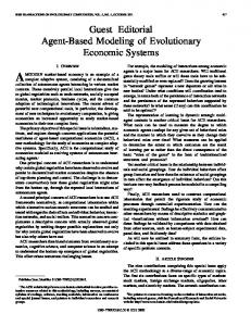
We have developed a simulation sofware which leads, using different dynamic model, to a best understanding of manipulation by adhesion phenomena. Simulations have proved the feasability of a manipulation solely based on adhesion forces and have shown the existancy of a "probe acceleration window" allowing the manipulation by adhesion [5]. To experimentaly validate capture and release acceleration windows, we achieved a manipulation of a single silicon sphere located on a polystyrene substrate. First, the task was simulated using the characteristics of experimental components. Manipulated objects are silicon chips of 50 to 200 p m . For the simulation, they are assimilated to Rb = 25 p m and Rb = 100 pm radius spheres. The probe is a silicon piezoresistive cantilever of mass mp = 0, l g . The task is achieved in atmospheric environment. Intersurfacic distances used in the model are defined in figure 3 .
Figure 3 : Intersurfacic distances notation : (a) capture, (b) release Equations related to the system dynamics are obtained by writing the dynamic equilibrium of each part of the system (probe and sphere). Condensed water on surfaces is a good lubricant at room temperature (friction coefficient p = 0) [ll],thus, in first approximation, no friction forces are introduced in the model. The dynamic model for the picking up task is then : mpYp = Fext - F Z d W - F:;p - F;Lec - mpg ?nbDl
= FCdW + Fb"p""+ F$"
- FLdW - F:'
(1) (2)
-F:iec - mbg yp = D 1 + 2 R b + D 2
(3)
where Ypis the instantaneous acceleration of the probe, Fext is the external force applied to the probe and the result of the applied speed law, FGdW are the Van der Waals forces, F z Y the capillary forces and FGLeCthe electrostatic forces. To complete this model, we have to add two constraints [5] : 0 a condition on d;, imposed by the substrate reaction (when ball contacts the substrate at D1 = Do =
-655-
0.4nm) : if D1 = 0 . 4 n m =j d ; ~2 0 a detachment constraint expressed by : Fext > 2Rb7TWball-water-substrate For the release task, the dynamic model is obtained as previously. Because particular design of the endeffector (see fig. 7) direction of Fezt is imposed by the square configuration of the piezoceramic dedicated to the acceleration generation. Then, the sloping angle 0 introduces a coefficient cos(: - e). The model is expressed by : 0
7T
mpYp = Fextcos(- - 0) - FbVpdW cos(0) 2
(4)
Manipulation time is supposed to be short enough to neglect ball-substrate deformation. Nevertheless, a detachment condition exists in the ball-probe contact because of deformations caused by adhesion forces. This condition is expressed by :
4
Simulation result analysis
The aim is to determine a "probe acceleration window" ensuring capture by adhesion. Simulation results of the manipulation appears on the curves showing the evolution of the two characteristic distances of the problem vs. time (Dl distance ball-substrate and Dzdistance ball-probe). The capture is done when D1 increases and D2 = Do (atomic contact distance). A time law is applied to the probe (ramps or steps). During simulations, the initial speed equals zero. The desired final speed (or step value) is reached in l nanosecond. Humidity is arbitrarily set to 50%. Condensed water on surfaces decreases the pull-off forces magnitude. Moreover, as surface energies are weak, combination with water allows to neglect the pull-off effect. Simulation results are illustrated on figs.4-5 for two sphere radius. Distances evolution vs. time are presented for the first acceleration ensuring the capture, and for the last one. Both simulations (for Rb = 25pm and Rb = 100pm).show that a weak acceleration allows the capture (Yp 40" (the probe tilting angle) low accelerations permit the release. When 8 < 40" acceleration needed to achieve the task are important (yP= 1 5 . 1 0 7 ~ . ~ - ' ) .
-
5
Description of the experimental setUP
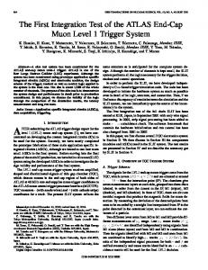
Experimental set-up we have developed is illustrated on fig. 8. The whole system lays on a vibration isolated table located in a dust control room where humidity is not controlable. It is composed of the following components : an observation system. It is an optical microscope equiped with long range optics (x10 and x50) with a working distance of 15 mm. 0 a micro/nano translation system. It is composed of two sub-systems : a three axis (XYZ) translator (Newport-micro-control) with a micrometer resolution over 25 mm displacement range. In the Z-direction, a piezo-translator placed in parallel gives a nanometer resolution over 12 p m displacement range (PI). 0 an end-effector. It is composed of a square on which
-
-656-
Figure 8: Experimental set-up
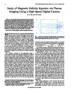
two piezo-ceramics are integrated and of a tipless piezoresistive cantilever (Nanosensor GmbH) . This cantilever is coated with gold The probe is used as contact sensor and as end-effector. Piezo-ceramics are dedicated to short range displacement (100 200 nm) and to the generation of the required accelerations to ensure manipulation by adhesion. This specific tool is presented in fig. 7. different 1 / 0 boards dedicated to the control of displacements and accelerations.
'.
-
'Coating process has been carried out in the Silicon Microsystems group at IEMN
.I..
figs 8-9, capture is efficient. Those experiments on capture highlights the importance of pull-off force as a condition of success. To ease the task, it is important to choose a low surface energy material, thus lowering the pull-off force [la]. When captured, by adhesion, silicon chip have to be released on the same substrate. First, the probe and the sticking object are tilted of an angle 0 > 40" (fig. 10). The system is then moved down with the manual translator till a tiny variation is observed on the sensor output. The final approach for contact is achieved with the piezotranslator till the -100 mV threshold is reached. The piezotranslator moves then up ( + l a p m ) to bring the probe out of the range of action of adhesion forces (fig. 11).
1
Figure 7: Tool for manipulation by adhesion
6
First experiments
Previous simulations have proved that the choice of experimental components allows the first acceleration ensuring capture by adhesion to be very low. It can then be easily generated. Experiments realized in atmospheric environment use : 0 a substrate in copper or polystyrene, 0 polycristalline silicon chips of 50 200 p m , 0 a gold coated piezoresistive cantilever (600pm x 140pm x 10pm and resonance frequency 3 5 k H z ) . The experimental steps for the capture task are the following : Silicon chips are first deposited on substrate. To avoid the X and Y precise positioning, which is not our first preoccupation, we consider a stack of chips which cover uniformaly the substrate after vibrating it. The probe is then moved over the chips, and moved down with the manual translator till a tiny variation of the output signal of the cantilever is observed. The final approach is then achieved by the piezotranslator till the output signal reach a threshold value of - 100 mV corresponding to an applied force of 2 . l o v 6 N (see fig. 7). The piezo-translator moves up bringing the probe and the object out of the range of action of adhesion forces at object-substrate interface. Large amplitude motion is subsequently provided by the manual translator. First experiments were carried out with a copper substrate. It possesses a high surface energy. Acceleration needed to overcome contact adhesion of silicon chips is then too important to be generated by the translators. The capture is then not efficient. The use of piezo-ceramics is needed to achieve the task in those conditions. A second experiment was realized with a polystyrene substrate. Experimental conditions are, in this case, those used for the theoretical studies. As shown on
-
Figure 8: Approach for capture (poly. substrate)
-
-657 -
Figure 9: Capture by adhesion (poly. substrate)
[3] H. Miyazaki, T. Sato, “Mechanical assembly of three dimensional microstructures under a SEM” , Proc. of the Int. Conf. on Mzcromechatronzcs for znform. and prec. equzp., pp 335-340, 1997. [4] Y. Zhou, B.J. Nelson, “Lessons learned in characterizing surface effect forces for micropart manipulation”, 2nd Int. Workshop on Mzcro robotzcs and Sysytems-IARP, China, pp 77-88, 1998. [5] Y. Rollot, S. RCgnier, J.C. Guinot, “Simulation of Micromanipulations : Adhesion Forces and Specific Dynamical Models” , Internatzonal Journal of Adheszon and Adheszues, vol. 19, p p 38-60, 1999.
Figure 10: Approach for release (poly. substrate)
[6] H. Krupp, “Particle Adhesion : Theory and Experiments”, Journal of Advances zn Collozd, vol. 1, pp 111-239, 1967. [7] Y. Rollot, S. RCgnier, J.C. Guinot, “Dynamical Model for the Micromanipulation by Adhesion” , Journal of Mzcro-Mechatronzcs, to be published 2000. Figure 11: Release of the object on the poly. substrate
[8] K.L. Johnson, K. Kendall, A.D. Roberts, “Surface Energy and the Contact of Elastic Solids”, Proc. R. Soc. Lond. , vol. A 324, p p 301-313, 1971.
7
[9] B.V. Derjaguin, V.M. Muller, Y.P. Toporov, “Effect of Contact Deformations on the Adhesion of Particles”, Journal of Collozd and Interface sczence, vol. 53, no 2, p p 314-326, 1975.
Conclusions
We have presented here a first experimental confirmation of 3D manipulation of micro-objects by adhesion in unconstrained environment. Experiments highlight the importance of pull-off forces as conditions of manipulation success. The use of piezoceramics would allow to generate high accelerations. It will lead to confirm acceleration range and to achieve manipulation on high surface energy substrate. The use of an haptic device would allow to manipulate quasiautomatically micro-objects. The system will then be use for the precise positionning of industrial micro laser diode.
[lo] D. Maugis, “Adhesion of Spheres : The JKRDMT Transition using a Dugdale Model”, Journal of Collozd and Interface Sczence,vol. 150, n o 1 , pp 243-269, 1992. [ I l l H. Yoshizawa, J. Israelachvili, “Fundamental Mechanisms of Interfacial Friction” Journal of Physzcal Chemzstry, vol. 97, pp 4128-4140, 1993. [12] J. Israelachvili, “Intermolecular and Surface Forces” Academzc Press, 1991.
References
F. Arai, D. Ando, T . Fukuda, Y. Nonoda, T. Oota, “Micro Manipulation Based On Micro-Physics” , Proc. of the IEEE/RSJ IROS, pp 236-241, 1995. G. Danuser, I. Pappas, B. Vogeli, W . Zesch, J . Dual, “Manipulation of microscopic Objects with nanometer precision”, International Journal of Robotic Research, 1997.
-658 -