it intractable for a counterfeiter to forge the generated signatures. .... FPGA. It allows us to send program, read, and erase operations to the device at will.
Extracting Device Fingerprints from Flash Memory by Exploiting Physical Variations Pravin Prabhu1 , Ameen Akel1 , Laura M. Grupp1 , Wing-Kei S. Yu2 , G. Edward Suh2 , Edwin Kan2 , and Steven Swanson1 1 2
UC San Diego, La Jolla CA 92093 Cornell University, Ithaca NY 14853
Abstract. We evaluate seven techniques for extracting unique signatures from NAND flash devices based on observable effects of process variation. Four of the techniques yield usable signatures that represent different trade-offs between speed, robustness, randomness, and wear imposed on the flash device. We describe how to use the signatures to prevent counterfeiting and uniquely identify and/or authenticate electronic devices.
1
Introduction
Many computing applications require the ability to uniquely identify a particular electronic device. Personalized services, digital rights management, and authentication schemes can all leverage per-device identifiers that are difficult (or impossible) to forge. At the same time, the growing economic importance and popularity of electronic devices has provided criminals with incentives to sell counterfeit items. Counterfeit phones [1], music players [4], and solid state drives [6] abound for sale on the Internet and in cut-rate electronics boutiques around the world. Counterfeiters may surreptitiously insert fake devices into the supply chain or sell fabricated, look-alike models directly to consumers. The result is substandard or non-functioning products, dissatisfied users, and economic losses. Due to the widespread use of flash memory, an identification or authentication scheme based on flash memory would be widely applicable. Flash memory suffers from idiosyncrasies such as unpredictable access latencies and a range of reliability problems. The variation that gives rise to these idiosyncrasies is due in part to random process variation, so the same variability can serve as the basis for extracting unique signatures from flash devices.
This paper examines seven techniques for extracting unique signatures from individual flash devices. These signatures depend on random changes in flash device behavior that arise from manufacturing variation and are detectable through the devices’ normal electrical interface. The variation occurs between chips and between the blocks and pages that make up the flash storage array. This means that a single signature generation technique can, in most cases, extract thousands of different signatures from different portions of a chip. The signatures are instances of the physically unclonable functions (PUFs) [17] that previous researchers have proposed for IC authentication and hardware-based cryptographic key generation. Similarly, our flash-based PUFs (FPUFs) can extract signatures to authenticate a chip and generate unpredictable numbers to generate cryptographic keys. Unlike most of other PUF circuits, however, FPUFs do not require any custom hardware circuits and work witwithh unmodified flash chips today. We consider several usage models for FPUFs. For instance, to identify counterfeit flash chips, the device manufacturer would extract the signature from each flash device and permanently mark it with a unique serial number (e.g., by using an write-once, antifuse memory). To check the authenticity of the device, the purchaser provides the device serial number to the manufacturer who responds with a challenge in the form of an array address. The purchaser uses the FPUF to extract the signature for that address and transmits the result back to the manufacturer, who checks for a match. In a consumer device the flash controller would use the FPUF to extract a unique identifier for the device to bind media content to the device or authenticate the device when it attaches to a provider’s network. In order to be useful, FPUFs must meet four criteria: They should be fast, not cause significant damage to the flash device, have a low false-positive rate, and should make it intractable for a counterfeiter to forge the generated signatures. We evaluate our seven FPUFs according the above criteria across fourteen flash devices. Our results examine the trade-offs between different FPUFs, and show that it is tractable to generate useful signatures in a few seconds. We also discuss usage scenarios that either use FPUFs directly or as part of a larger system to provide useful identification or authentication services. Section 2 describes usage scenarios for FPUFs. Section 3 gives a brief overview of the details of flash memory operation relevant to our study. Section 4 presents our FPUFs, analyzing the trade-offs and effectiveness of each. Section 5 describes related work and Section 6 concludes. 2
Manufacturer flash System Integrator
Malicious Group Bad flash
Supply Chain
flash
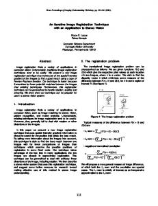
Fig. 1. Threat model for counterfeit detection
2
Applications
FPUFs have a wide range of applications because they require no special hardware and flash devices are ubiquitous. Below we describe three applications for the FPUFs we describe in this paper.
2.1
Counterfeit Detection
Figure 1 illustrates the threat model for chip counterfeiting that we assume in this paper. In the model, a trusted manufacturer makes flash chips and a trusted consumer purchases the chips through an untrusted supply chain. The consumer in this case is assumed to be a system integrator that purchases individual flash chips, not the enduser. The system integrator would have direct access to the flash chips and be able to perform low-level flash operations such as read, write, and erase operations at will. An adversary attempts to inject their own counterfeit or malicious chips into the supply chain, masquerading them as brand-name chips in order to make a profit at the expense of the manufacturer and/or deliver a malicious payload to the end-user. We assume the adversary has access to the supply chain but not the chip manufacturing process or the system integrator’s facilities. Our technique focuses on preventing the adversary from injecting fake or bad chips into the supply chain. Non-working chips are easy to detect and remove from the supply chain. We assume the adversaries do not have their own fabrication facilities, as this is prohibitively expensive. Under this threat model, a unique physical signature for each flash chip can be used to detect counterfeit devices by having the manufacturer and the system integrator measure and compare signatures. 3
2.2
Device Identification
Many modern computing devices contain a flash memory IC for non-volatile storage. Therefore, the proposed authentication technique is useful as a way to provide a secure hardware-based identifier for a device. If a device provides a low-level interface to a flash chip with direct access to read/write/erase operations, the FPUF signatures of the flash can be obtained externally and used to uniquely identify or possibly authenticate a device. As an example, such a capability can provide a way to authenticate mobile devices in a way that cannot be bypassed by malicious software even without adding any new hardware module. 2.3
Random Number Generation
The effects that our FPUFs exploit are probabilistic and vary both due manufacturinginduced variations and from operation-to-operation. Therefore, variation in device behavior can potentially be used to provide physical randomness in a random number generator.
3
Flash Memory
The FPUFs we describe in Section 4 rely on details of flash cells and how flash chips organize them into memory arrays. This section summarizes the characteristics of flash memory that we rely on for this study. 3.1
Flash Cells
Flash memory uses a single floating gate transistor to store one or more bits. The transistor includes an electrically isolated floating gate between the channel and the gate. To maximize density, NAND flash arranges between 32 and 64 floating gate transistors in series as a flash chain. Charge on the floating gate affects the threshold voltage of the transistor, so the chip can read one cell in a chain by turning on all the transistors in the chain other than the target. By applying a voltage to the control gate and measuring current flow through the target cell, the chip can effectively measure its threshold voltage. Changing the value of a cell requires moving electrons on or off of the cell’s floating gate. The “program” operation moves electrons onto the gate and changes a cells value from a logical ’1’ to a logical ’0’. Programming uses a process called Fowler-Nordheim 4
tunneling that draws electrons onto the floating gate by applying a large voltage between the gate and channel. An “erase” operation removes electrons from the gate by applying an opposite voltage between the gate and channel. Unlike the program operation, the erase operation affects the entire chain at once. Some flash devices can store n bits per transistor by programming and measuring 2n voltage levels on the floating gate. These multi-level cell (MLC) devices offer increased density, but also reduced reliability and performance than single-level cell (SLC) devices.
3.2
Array Organization
Flash chips organize thousands of flash chains into a memory array that support highbandwidth access by reading, writing, and programming many flash cells in parallel. The basic unit in a flash array is a “block” comprised of between 16 and 32 thousand parallel flash chains. Each cell in a chain belongs to a different “page,” so the nth cells across the chains comprise the nth page in the block. A single word line connects the gates on all the transistors in a page. In MLC devices, each bit in a single cell resides in a different page to prevent correlated errors between consecutive bits in a single page. Read and program operations apply to individual pages, while erase operations apply to an entire block. An entire chip contains thousands of independent blocks. Due to this organization, it is possible for two bits in separate pages to electrically influence each other. During a program or read operation, unselected word lines experience an intermediate gate voltage, allowing current to flow to the target cell. This intermediate voltage exerts an electromagnetic stress on the oxide layer of each bit, resulting in a mild programming force. After many operations, these program and read disturb effects can cause bit errors. For program operations, the effect is especially strong for cells physically adjacent to the programmed page. This is due to capacitive coupling between the selected word line and the physically adjacent flash cells.
3.3
Variation Mechanisms
Flash cells are packed as closely together as possible to maximize density, so small variations in feature geometry or oxide thicknesses can have a measurable impact on both individual cell behavior and inter-cell effects (e.g., capacitive coupling between cells). For instance, some cells may be more or less susceptible to program disturb, read disturb, or program/erase-induced wear. 5
The variation also affects how difficult it is to program or erase pages and blocks. Both operations are iterative in flash memories: The chip partially programs or erases the cells, checks their value, and program or erases them again as needed. The result is that operation latency varies between pages and between blocks. Since the physical effects underlying these variations are random (e.g., shot noise in dopant ion distributions), we can expect the pattern of variation between pages, blocks, and chips to be uncorrelated. Since the variation is random, FPUFs based on detailed measurements operation latency and unreliability should be unique across flash devices.
4
Techniques
Process technology-induced variation provides the basis for extracting signatures from flash devices, but the details of how we extract variation information will determine the FPUFs’ effectiveness. This section describes our approach to extracting and using raw variation information to create signatures that can differentiate between individual chips. First, we discuss qualities desirable in a flash chip signature. We then describe the FPUFs and evaluate them according to those criteria. 4.1
Data Collection Hardware
To extract signatures from the flash devices, we use a testing board that contains two flash chip test sockets. This board connects to a Xilinx XUP board running Linux. The system accesses the flash memory via a custom-built flash controller running on the FPGA. It allows us to send program, read, and erase operations to the device at will. The FPGA on the XUP board implements a custom flash controller that supports timing measurements with 10 ns resolution. We evaluate FPUFs with a set of chips of varied geometry. Table 1 summarizes the flash chips we use in this study. 4.2
Evaluating FPUFs
FPUFs differ along several axes and trade-offs across these axes will determine whether a particular FPUF is a good fit for a given application. In this work, we consider four criteria for evaluating FPUFs. First, an FPUF should be able to differentiate between different chips with very high confidence. That is, the signatures from two different devices (or portions of a device) 6
Table 1. Parameters for the 27 flash devices we studied in this work.
Name
Manufacturer Cap. (GBit) Tech. Node (nm) Pg Size (B) Pgs/Blk
A-MLC16-{1, 2} A A-SLC8 A A-SLC2-{1, 2} A A-SLC4 A B-SLC4-{1...5} B B-MLC8-{1...5} B B-MLC32-{1, 2, 3} B B-MLC128 B B-MLC2 B C-MLC64 C D-MLC32 D E-SLC8 E E-MLC8 E H-MLC16-{1, 2} H
16 8 2 4 4 8 32 128 2 64 32 8 8 16
72 72 34
41
4096 2048 2048 2048 2048 2048 4096 4096 2048 8192 4096 2048 4096 4096
128 64 64 64 64 128 128 256 64 128 128 64 128 128
should vary randomly and widely from one another. At the same time, the signatures must be robust in that repeatedly extracting a signature from the same device should give very similar, if not identical, results. Second, FPUFs should be fast. Some applications require extracting a signature from every flash chip coming off an assembly line. If an FPUF takes many hours, it will not be practical to apply it at large scales. Third, it should be difficult to forge the results of an FPUF for a chip. If FPUFs are going to be useful in authentication applications, it must be infeasible or impossible for the counterfeiter to forge the signature. In particular, it should not be possible to store the signature on the chip and “replay” it when the chip detects that an FPUF is being applied. Finally, applying an FPUF should not significantly damage the flash chip. Modern, high-density flash blocks can tolerate as few as 3000 program/erase cycles before becoming unreliable. If an FPUF renders part of the chip unusable, the FPUF will be less useful.
4.3
Program Disturb The first FPUF measures variation in how cells respond to the program disturb ef-
fects described in Section 3. To create the signature, we erase a block and then repeatedly program one page in the block. Between each program, we read physically 7
Algorithm 1 Extracting program disturb-based signatures ProbePage and ObservedPage are physically adjacent in TheBlock. EraseBlock(TheBlock) for Cycle = 0 . . . 10000 do ProgramAllZeroes(ProbePage) bits = ReadPage(ObservedPage) for b = 1 . . . BitsPerPage do if bits[b] then Signature[b] = Cycle end if end for end for
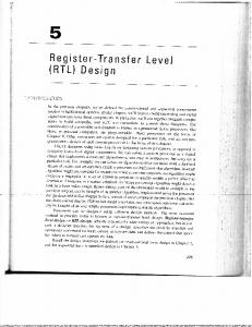
adjacent pages for program disturb-induced errors. For each bit in the adjacent page, we record the number of programs required to cause the first bit error. Those values comprise the signature. If program disturb never affects the bit, then the value for that position is set to 0. Algorithm 1 contains pseudocode for this process. The resulting signature is noisy: Extracting the signature from a single page repeatedly will yield different signatures. Signatures for the same page are highly correlated, however. Figure 2(a) is a scatter plot of two signatures from one block on B-MLC8-1. (Table 1 summarizes the flash chips we use in this study). Figure 2(b) shows the same plot for pages in two different devices, and shows that the two signatures are not strongly correlated. The noise in the correlations are due to the probabilistic nature of program disturb. Since each program operation is iterative, the number of programming pulses that act on the disturbed cells will vary from trial to trial. We use a formal correlation metric (the Pearson correlation) to measure the robustness of the signatures and their ability to uniquely identify individual flash devices. To measure the correlation between two signatures, we form a pair, (X, Y ) for each bit position in a flash page. The pair contains the number of program disturbs required to flip that bit in each of the two extracted signatures. We then compute the Pearson correlation as P (X, Y ) =
E[(X − µX )(Y − µY )] . σX σY
(1)
The nearer P (X, Y ) is to 1, the more similar to the two signatures are. If P (X, Y ) is near zero, the signatures are very dissimilar. Our measurements of the correlation between signatures from the same pages and between signatures from different pages show that the program disturb-based signatures 8
10000
8000 6000 4000 2000 2000 4000 6000 8000 10000 Error Cycle (E-MLC-1 Trial 1)
Error Cycle (E-MLC-2 Trial 1)
Error Cycle (E-MLC-1 Trial 2)
10000
8000 6000 4000 2000 2000 4000 6000 8000 10000 Error Cycle (E-MLC-1 Trial 1)
Fig. 2. Program disturb signature correlation Extracting a program disturb signature from the same page twice gives highly correlated signatures (a). Signatures from different pages are uncorrelated (b).
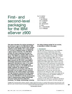
can reliably distinguish between flash devices. For instance, the correlation between the two signatures from the same page in Figure 2(a) is 0.94, while the two signatures in Figure 2(b) have a correlation of just 0.012. Figure 3 extends this analysis to a larger population of devices. It illustrates the selectivity of our program disturb-based signature. We extracted signatures from one block from each of 10 chips (B-MLC8-1...5 and B-SLC4-1...5). The histogram shows the distribution of statistical correlations across all pairs of signatures, including signatures from the same block pair with each other. The white bars measure the correlation of signatures from the same block. The black bars are pairings of two different chips. The distributions of both sets are very tight and there is a large gap between the two groups, demonstrating that the likelihood of false positives (i.e., of two different blocks producing signatures that would appear to be the same) is very low. Since this FPUF relies on per-cell variation in disturb sensitivity, it can extract a signature from each of the thousands of pages in a flash device. While this number is large, it is still linear in the size of the flash devices. As a result, this FPUF (like all the FPUFs we describe) is “weak” in that it cannot respond to an exponential number of challenges. Extracting a single program disturb-based signature takes between 1 and 5 minutes, since it takes several thousand program operations to disturb a significant fraction of bits. We can reduce this latency and sacrifice some of the signature’s power by limiting the number of program operations, k. Figure 4 shows the effect of varying k on the gap between signatures from the same chip and signatures from different chips. Each line 9
Instances
6 5 4 3 2 1 0
Same Chip, Same Page Different Chip, Same Page
0
0.5
1.0
R-Correlation Fig. 3. Selectivity of the program disturb-based FPUF. The black and white bars are histograms of correlations between signatures from different pages and signatures from the same page, respectively. The large gap between the distributions shows program disturb signatures can reliably differentiate between different chips.
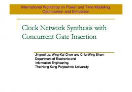
in the graph represents a different pair of signatures from B-MLC8-1...5. The dashed lines are pairs of signatures from the same page. The solid lines are mismatched pairs. The vertical axis measures the correlation between the two. The data show that for k < 4500, the signatures do not reliably distinguish between devices, but that by 5000 they can do so reliably. Limiting signature extraction to 5000 programs reduces extraction time to just 50 seconds. In order to forge a chip’s signature, the counterfeiter would need to store the signature information inside the flash chip, detect attempts to extract the signature, and replay the signature back in response. Extracting a program disturb signature requires a unusual and easy-to-detect access pattern, so replaying the signature is a definite danger. To make forging signatures infeasible, the manufacturer can collect a signature for a random subset of the pages. In response, the counterfeiter would need to store the signatures for all the pages. Whether this is feasible or not depends on the information content of the signatures. Ideally, a signature would extract more than one bit of signature information for each bit in the page or block it targets. This would imply that storing the signatures for the chip would require more capacity than the chip can provide. The data in Figure 2 show that the values in the signature fall between 3000 and 10,000. Representing each value in a signature precisely would require about 10 bits per flash cell, making it impossible to store signatures for every cell in the flash device itself. However, because the signatures are noisy, the counterfeiter would only need to store an approximation of the signature, which would require fewer bits. For instance, the counterfeiter could store quantized signatures, restricting cycle counts to a few values in the forged signature. 10
R-Correlation
1 0.5 0
Same Chip, Same Page Different Chip, Same Page
-0.5 -1
3000
4000
5000
6000
7000
Program Cycles
8000
9000 10000
Fig. 4. Sacrificing accuracy for speed Program disturb signatures can more reliably distinguish between different chips if the number of disturb operations is larger. The dotted lines measure correlation for signatures for the same page. Solid lines are pairs of different pages. Using more than 5000 program operations does not provide significant benefit.
We evaluated this forgery technique by quantizing signatures and measuring their correlation with the original. We found that quantizing the signature into four values would still provide correlations over 0.8. Storing the quantized signature would require two bits of signature data per flash bit. We measured the entropy of the quantized signatures as H=−
X
pi lnpi
(2)
i=0...3
where pi probability that a bit had value i in the quantized signature. The entropies were close to two, suggesting that the signatures are not significantly compressible. As a result, forging signatures by storing even compressed quantized signatures in the chip is not feasible, requiring a larger amount of storage than the authentic device. The final concern is that extracting the program disturb signature will cause irreparable damage to the page. Extracting a signature requires one erase operation and many program operations. We have measured the reliability of the flash cells after repeated programming and found that the programs do not significantly affect reliability.
4.4
Read Disturb
The second FPUF uses read disturb instead of program disturb to extract signatures. We first erased the entire block and then program it with random data. Next, we read from each page in the block several million times to induce read disturb. After every 1000 read iterations, we checked each page in the block for errors. If we observed an error on a page, we recorded the bit, page, and cycle of the error. We repeated this process 10 million times. We use the read cycle counts for all the bits in the block as the signature. 11
Read-disturb signatures are less noisy than program disturb signatures, with correlations between multiple signatures from the same block averaging 0.98. Correlations between signatures from different blocks were extremely low: 0.0 for tests chip of BMLC8-1 through B-MLC8-5. The main disadvantage of this technique is that it is slow. It takes about 6 hours to extract a useful signature from MLC chips. SLC chips are less susceptible to read disturb, so we were not able to extract useful signatures from any SLC chips. Finally, this technique is less resistant to counterfeiters than the program disturb technique. Quantizing the signatures to just a single bit provides correlations in excess of 0.98. Furthermore, the signatures we can extract in six hours have only between 3 and 7 disturbed bits. Storing this data for a single block would require fewer than 70 bits, suggesting that it might be possible to store all of a forged chip’s signatures in the chip. Extracting this kind of signature is, however, non-destructive, since the read operation does not move charge on or off of the floating gate.
4.5
Program Operation Latency
The next two FPUFs use per-bit variation in program latency to create a signature. The FPUF programs one bit at a time in a page, and records the latency for each operation. We tested two variations of the write latency signature: single-page and multi-page. Each variation requires erasing the block, first. The single-page version programs each bit in a single page within a block: the first program operations programs a single ’0’ followed by ones, the second program operation programs two ’0’s followed by ones, and so on. In the multi-page version, we program just the nth bit in page n, so the programs are spread across all the pages in the block. After every n programs, we erase the entire block to make sure that each program goeas to an empty page. Each cell contributes a single measurement to the string of latency values, resulting in the desired signature. We extracted signature pages in two SLC and two MLC chips: H-MLC16-1, HMLC16-2, A-SLC2-1 and A-SLC2-2. Both versions of the technique had similar selectivity: Correlations between signatures from the same page was between 0.83 and 0.84, between different pages it was between 0.02 and 0.03. While this range is not as wide as it was for the program-disturb based signatures, the gap between correlations for the same pages vs. different pages is still very large. 12
R-Correlation
R-Correlation
1 0.8 0.6 0.4 0.2 0 -0.2 -0.4 -0.6 -0.8 -1
Same Chip, Same Page Different Chip, Same Page 0
2000 4000 6000 8000 10000
Bits
1 0.8 0.6 0.4 0.2 0 -0.2 -0.4 -0.6 -0.8 -1
Same Chip, Same Page Different Chip, Same Page 0
2000 4000 6000 8000 10000
Bits
Fig. 5. Single page write latency selectivity. For SLC devices (a) just 100 per-bit program latency measurements give correlations over 0.8 and provide good selectivity. For MLC devices (b) 100 measurements also give good results, and selectivity actually decreases as the number of measurements rises (see text).
Extracting a program latency signature from a block requires thousands of program operations and takes over 5 seconds per block. Figure 5 shows the effect of truncating the signatures. For both SLC and MLC chips just 100 measurements is sufficient to give high selectivity. In fact, for MLC chips using more than 1000 measurements reduces selectivity as all signatures from different chips become correlated. This effect is due to systematic variations in program latency that are a product of the chip’s memory array architecture rather than process variation. We can account for this systematic variation by measuring latencies across many pages and subtracting the average per-bit latency from the measured latency for page we are targeting. The resulting signatures reduce correlation between mismatched full-length multi-page MLC signatures from 0.7 to 0.5. This is an improvement, but still suggests that smaller signatures are superior in this case. The main drawback of this technique is that the information content of the signatures is low. Our latency measurements take on ∼20 discrete values 3 , so storing each takes just a few bits. Since smaller signatures are preferable for this technique, forging these signatures will be even easier. Signature generation is, however, very quick and causes almost no wear on the device: It takes between 1 and 3 seconds to generate a 1000 measurement signature, and the process takes a single program/erase cycle to extract a signature from a block.
3
The discrete values are a result of the iterative process of flash programming. Each program operation comprises a series of programming “pulses” under control of the flash chip’s internal state machine.
13
4.6
Other potential signatures
We have not explored all of the potential sources for flash chip signatures, but we did examine several additional techniques that turned out not to be useful. We measured the erase latency for each block in a device and used
Erase latency
the resulting sequence of values to form a signature. This signatures was ineffective because erase latency times showed little variation and were inconsistent for individual blocks. Read latency
Per-page read latency also varies little between devices, so it makes a
poor signature. In fact, the read latency of the entire device is constant for SLC chips. Whole-page program latency
In addition to the per-bit measurements described
above, we tried whole page program latency as a signature. It was ineffective due to lack of variation. Program/erased wear
We have measured the susceptibility of individual cells to
program/erase-induced wear, but extracting such a signature takes at several hours and renders the target block unusable. Furthermore, as the work in [8] demonstrates, it would be easy to identify which blocks the manufacture had extracted signatures from by measuring wear-induced changes in program and erase latency. It would be easy, therefore, for a forger to determine which signatures to store and play back.
4.7
Summary
Table 2 summarizes the results for all the FPUFs we studied. It contains the range of values we measured for the gap in correlation values comparing signatures from the same chip and those from different chips, the time required to extract a signature, the number of bits (as measured via the entropy calculation given above) per signature, and the number of program and erase cycles extracting a signature requires. The results show that FPUFs based on program disturb rate and program latency are the most useful. The program disturb FPUF does the best job of distinguishing between different chips, but this comes at the price of increased extraction time – it has the second longest extraction time of the useful techniques. The signatures it generates are also the most information-dense, making it the best choice for applications where latency is less important. 14
Table 2. FPUF summary Three of the seven FPUFs we tested provided useful signatures in a few minutes. Read disturb also provide useful signatures but it is too slow to be practical.
FPUF
Correlation Gap (SLC) (MLC)
speed bits program erase points (s) sig. cycles cycles used
Program disturb 0.80-0.95 0.85-0.90 100 160k 10000 Read disturb n/a 0.98-1.00 86400 1.1k 1/page Single-page bit prog. latency 0.65-0.85 0.40-0.90 15 20k 10000 Multi-page bit prog. latency 0.70-0.85 0.00-0.10 20 20k 10000 Erase latency 0.00 0.25-0.90 300 6k 0 Read latency 1.00 0.00 300 0 0 Page program latency 0.65-0.75 0.00 300 78k 1/blk
1 1 1 1 1/blk 0 1/blk
1 page 1 page 10k 10k blks/chip pgs/chip pgs/blk
The program latency FPUF is the fastest of the useful FPUFs, and its signatures still contain about 20Kbits of information. For performance-critical applications (e.g., for extracting signatures from every flash chip produced by a large manufacturer), it is the obvious choice.
5
Related Work
Traditional techniques to authenticate hardware devices rely on a secret key and cryptographic operations. For example, a trusted hardware module such as a smartcard contains a private key in internal storage and generates a cryptographic signature to prove its authenticity. While cryptographic solutions are widely used, they require significant computing resources as well as key management procedures. As a result, traditional digital signatures are not well-suited for low-cost device authentication. More recently, researchers have proposed to use inherent hardware fingerprints based on unique physical characteristics for identification and authentication. For example, it is widely known that significant process variations exist in an IC fabrication process, which make analog characteristics different from instance to instance even for a single design [2, 3, 12]. These process variations have previously been used to identify ICs by exploiting fluctuations in drain currents [11] or initial states of bi-stable elements such as latches [16]. While useful for circuit identification, these circuits are not suitable for security applications because they only provide a single number. An intelligent adversary can easily read out an ID and create a duplicate. For security applications, a notion of Physical Unclonable Functions (PUFs) has been proposed to extract many signatures from inherent analog properties of physical 15
systems. Conceptually, a PUF is a function that maps challenges to responses using an intractably complex physical system. For example, the initial idea of Pappu [13] proposed to use light scattering patterns of optically transparent tokens. This construction is often called an optical PUF and can generate an extremely large number of patterns can be generated depending on how a light source is setup. For silicon devices, researchers have shown that silicon PUFs can be constructed to produce unique responses for each IC instance, exploiting random manufacturing variations. For example, silicon PUFs may extract unique delay characteristics using ring oscillators [7] or race conditions between two identical delay paths [10]. Alternatively, recent studies showed that initial states of bit-stable elements such as SRAM cells are also unique for each IC instance [5]. The silicon PUFs can be implemented as either custom circuits or reconfigurable logic on an FPGA [15, 9, 14]. PUF responses can be directly used as fingerprints to identify each IC instance or combined with error correction techniques to generate a cryptographic secret key [17]. The proposed flash fingerprints can be seen as a new type of PUF that can generate many fingerprints depending on the part of a flash chip that is used. While the overall idea of exploiting manufacturing variations for device fingerprinting is similar to other PUFs, the proposed FPUF is the first to exploit unique physical characteristics of flash memory. Moreover, the proposed approach does not require any change to today’s commercial flash ICs while most of other silicon PUFs require carefully designed custom circuits.
6
Conclusion
This paper has described seven different FPUFs that can extract unique signatures from flash memory devices. We described a set of desirable characteristics for FPUFs and experimentally evaluated them using thirteen different flash memory devices. Our results show that four of the FPUFs produce reliable signatures, but that they vary in terms of speed, selectivity, the amount of damage they do to the flash devices, and the ease with which a counterfeiter could forge them. We conclude that flash-based FPUFs can provide a reliable means of uniquely identifying individual flash devices and, by extension, can aid in identifying and authenticating electronic devices.
16
References 1. D. Barboza. In china, knockoff cellphones are a hit. The New York Times, April 2009. 2. D. S. Boning and J. E. Chung. Statistical metrology: Understanding spatial variation in semiconductor manufacturing. In Proceedings of SPIE 1996 Symposium on Microelectronic Manufacturing, 1996. 3. K. A. Bowman, S. G. Duvall, and J. D. Meindl. Impact of die-to-die and within die parameter fluctuations on the maximum clock frequency distribution for gigascale integration. Journal of Solid-State Circuits, 37(2):183–190, Feb. 2002. 4. J. Cheng. Beware of counterfeit ipods! Ars Technica, April 2006. http://arstechnica.com/apple/news/2006/04/3651.ars. 5. W. P. B. Daniel E. Holcomb and K. Fu. Initial SRAM state as a fingerprint and source of true random numbers for RFID tags. In Proceedings of the Conference on RFID Security. 6. http://sosfakeflash.wordpress.com/. 7. B. Gassend, D. Clarke, M. van Dijk, and S. Devadas. Silicon Physical Random Functions . In Proceedings of the Computer and Communication Security Conference, New-York, November 2002. ACM. 8. L. Grupp, A. Caulfield, J. Coburn, S. Swanson, E. Yaakobi, P. Siegel, and J. Wolf. Characterizing flash memory: Anomalies, observations, and applications. In MICRO-42: 42nd Annual IEEE/ACM International Symposium on Microarchitecture, pages 24 –33, 12 2009. 9. G. S. J. Guajardo, S. Kumar and P. Tuyls. FPGA intrinsic PUFs and their use for IP protection. In Cryptographic Hardware and Embedded Systems (CHES), 2007. 10. J. W. Lee, D. Lim, B. Gassend, G. E. Suh, M. van Dijk, and S. Devadas. A technique to build a secret key in integrated circuits for identification and authentication application. In Proceedings of the Symposium on VLSI Circuits, page 176159, 2004. 11. K. Lofstrom, W. R. Daasch, and D. Taylor. IC Identification Circuit Using Device Mismatch. In Proceedings of ISSCC 2000, pages 372–373, February 2000. 12. S. R. Nassif. Modeling and forecasting of manufacturing variations. In Proceedings of ASP-DAC 2001, Asia and South Pacific Design Automation Conference 2001. ACM, 2001. 13. R. Pappu. Physical One-Way Functions. PhD thesis, Massachusetts Institute of Technology, 2001. 14. P. S. S. Morozov, A. Maiti. A comparative analysis of delay based PUF implementations on FPGA. In Proceedings of the 6th International Symposium on Applied Reconfigurable Computing, 2010. 15. R. M. G. S. S.S. Kumar, J. Guajardo and P. Tuyls. The butterfly PUF protecting IP on every FPGA. In Proceedings of IEEE International Workshop on Hardware-Oriented Security and Trust, 2008. 16. Y. Su, J. Holleman, and B. Otis. A 1.6pj/bit 96% stable chip-ID generating circuit using process variations. In Proceedings of the IEEE International Solid-State Circuits Conference (ISSCC), 2007. 17. G. E. Suh and S. Devadas. Physical Unclonable Functions for Device Authentication and Secret Key Generation. In Proceedings of the 44th Conference on Design Automation, 2007.
17