Process declaration. Process declaration is similar to C++ member function declaration within module class. ...... typedef struct vector_port { char vec_name [50];.
Ain Shams University – Faculty of Engineering Computer and Systems Engineering Department
C-based high-level synthesis using SystemC A Thesis Submitted in partial fulfillment of the requirements for the degree of Master of Computer Engineering
Submitted By Samer I. Mohamed Aly B.Sc. Electrical Engineering (Computer & Systems Engineering) Ain Shams University, 1998 Supervised By Prof Dr. Ashraf El-Farghaly Salem Dr. Ayman Mohamed Wahba
Cairo 2005
APPROVAL SHEET
Name
Samer I. Mohamed Aly
Thesis
C-based high level synthesis using SystemC
Degree
Master of Computer Engineering
Examiners Committee Name, Title and Affiliation
Signature
1.
………………..
2.
………………..
3.
………………..
4.
………………..
Date:
1
/ / 2005
STATEMENT
This dissertation is submitted to Ain Shams University for the degree of Master of Science in Computer Engineering. The work included in this thesis was carried out by the author at the Computer and Systems Engineering Department, Faculty of Engineering, Ain Shams University. No part of this thesis has been submitted for a degree or qualification at other university or institution. Name
Samer I. Mohamed Aly
Signature Date
/ / 2005
2
ABSTRACT
C-BASED HIGH LEVEL SYNTHESIS USING SYSTEMC Samer I. Mohamed Aly Master of Science in Computer Engineering Ain Shams University, 2005
Silicon technology now allows us to build chips consisting of tens of millions of transistors. This technology promises new levels of system integration onto a single chip but also presents significant challenges to the chip designer. As a result many ASIC developers and silicon vendors are re-examining their design methodologies, searching for ways to make effective use of huge numbers of gates now available These designers see current design tools and methodologies as inadequate for developing million gates ASICs from scratch. There is considerable pressure to keep design team size and design schedules constant even as design complexities grow. Tools are now providing the productivity gains required to keep pace with the increasing gate counts available from deep sub micron technology Design ruse is the use of pre-designed and pre-verified cores and taken to be the most promising opportunity to bridge the gap between the available gate count and designer productivity. In this thesis, we focus on using SystemC, a new modeling methodology based on C++, to describe an effective methodology for creating reusable designs to be used in a system-on-chip (SOC).
Keywords: SoC, SystemC, Design reuse, ASIC.
3
ACKNOWLEDGMENT
First of all I want to thank God for everything and one of these things is supporting me to share in publishing this thesis as a small contribution for our nation development and progress. Second, I wish to give my deep appreciation to my teacher, instructor and advisor Prof. Dr Ashraf Salem who stands beside me from the beginning through technical support based on his familiarity with ideas and needs of the thesis, Finally I wish to thank him for his continuous effort and time to produce this thesis in an efficient and professional way. Third, I wish to thank Dr. Ayman Wahba whose supporting with whatever technical information is an added value and contribute to publish this research in the best way. Forth, I want to thank my company Mentor Graphics, my managers and colleagues there, for their support and for using company resources, tools and valuable time. Finally, I’d like to thank my family who deserve more than thanks for their support and encouragement all over my life.
4
TABLE OF CONTENTS
Approval Sheet ..................................................................................................................... 1 Statement............................................................................................................................... 2 Abstract ................................................................................................................................. 3 Acknowledgment ................................................................................................................. 4 Table of Contents ................................................................................................................ 5 List of Figures....................................................................................................................... 9 List of Tables ......................................................................................................................12 Glossary ...............................................................................................................................13 Chapter 1 ............................................................................................................................15 Introduction .................................................................................................................15 1.1 SystemC Modeling Methodology …. ...............................................................15 1.2 Linting methodology …. ....................................................................................15 1.3 High level synthesis methodology…. ...............................................................16 1.4 Thesis summary…. ..............................................................................................16 1.5 Organization of the thesis…. .............................................................................17 Chapter 2............................................................................................................................18 SystemC modeling Methodology ........................................................................18 2.1 Introduction .........................................................................................................18 2.2 System constructs description ...........................................................................19 2.2 .1 Modules ....................................................................................................19 2.2.2 Ports ...........................................................................................................20 2.2.3 Signals ........................................................................................................22 2.2.4 Reading and wirting ports and signals .................................................23 2.2.5 Processes ...................................................................................................24 2.2.6 Reading and wirting processes ..............................................................26 2.2.7 Types of processes ..................................................................................26 2.2.8 Data types .................................................................................................28 2.3 SystemC synthesizable subset ............................................................................28 2.3.1 Nonsynthesiable SystemC constructs ..................................................28 2.3.2 Nonsynthesizable data types .................................................................33 2.3.3 Recommended data types for synthesis ..............................................33 2.4 SystemC advanteges.............................................................................................34 Chapter 3............................................................................................................................35 SystemC linting Methodology ...............................................................................35 3.1 Overview of coding guidelines ..........................................................................35 3.2 Lexical guidelines..................................................................................................36 3.2.1 Rules for naming conventions .............................................................36 3.2.2 Include header in source files ...............................................................37 3.2.3 Use comments ........................................................................................38 3.2.4 Keep commands in separate lines .......................................................38 3.2.5 Line length ...............................................................................................38 5
3.2.6 Indentation ..............................................................................................39 3.2.7 Avoid SystemC reserved words ...........................................................40 3.2.8 Port ordering ...........................................................................................40 3.2.9 Port maps .................................................................................................41 3.2.10 SystemC module and methods implementation ............................41 3.2.11 Use functions ........................................................................................41 3.2.12 Use loops and arrays ............................................................................42 3.2.13 Avoid use hard-coded numeric values .............................................42 3.3 Coding guidelines for synthesis ........................................................................43 3.3.1 Avoid latches ...........................................................................................43 3.3.2 Avoid combinational feedback ............................................................45 3.3.3 Specify complete sensitivity list............................................................45 3.3.4 Case statement versus if-else statement .............................................46 3.4 Partitioning for synthesis ....................................................................................48 3.4.1 Register all outputs .................................................................................48 3.5 Practical implementation ...................................................................................49 3.5.1.ScLint tool features.................................................................................49 3.5.2 ScLint data structures.............................................................................49 3.5.3 ScLint parsing rules ................................................................................52 3.5.4 ScLint linting algorithms .......................................................................54 3.5.5 ScLint error/warning messages ...........................................................55 3.5.6 ScLint linting results ...............................................................................55 Chapter 4............................................................................................................................63 SystemC Synthesis Methodology..........................................................................63 4.1 Introduction ..........................................................................................................63 4.2 Behavioral synthesis process ..............................................................................65 4.2.1 CDFG generation...................................................................................65 4.2.2 Resource allocation ................................................................................66 4.2.3 Scheduling ................................................................................................67 4.2.4 Register allocation...................................................................................69 4.2.5 Register sharing .......................................................................................69 4.2.6 Library binding ........................................................................................69 4.2.6.1 Definition ..........................................................................................69 4.2.6.2 Goal of library binding ...................................................................69 4.2.6.3 Importance of library binding .......................................................69 4.2.6.4 Practical approaches to library binding........................................70 4.2.6.5 Library binding formulation ..........................................................70 4.2.6.5.1 Terminology ...............................................................................70 4.2.6.5.2 Conditions for network covering problem ..........................71 4.2.6.5.3 Algorithms for covering problem ..........................................71 4.2.6.6 Structural approach...........................................................................71 4.2.6.6.1 Covering algorithm based on structural approach..............71 4.2.6.6.2 Tee-based matching problem .................................................74 4.2.6.6.3 Optimal tree covering...............................................................75 4.2.6.6.4 Disadvantages of structural matching ...................................76 4.2.6.7 Boolean approach .............................................................................76 6
4.2.6.7.1 Covering algorithm based on Boolean approach................76 4.2.6.7.2 Conclusions ................................................................................77 4.2.6.8 Field Programmable Gate Array (FPGA) mapping ...................78 4.2.6.8.1 Introductions .............................................................................85 4.2.6.8.2 Binding for different FPGA architectures ...........................86 4.2.6.9 Rule based library binding ...............................................................87 4.2.6.9.1 Introductions .............................................................................87 4.2.6.9.2 Comparison of algorithmic and rule-based binding ...........87 4.2.7 Data path and state machine extraction .............................................87 4.2.8 Net listing .................................................................................................88 4.3 Area estimation techniques ................................................................................91 4.3.1 basic concepts .........................................................................................91 4.3.2 area estimation algorithm ......................................................................92 4.3.2.1 CLBs count .......................................................................................92 4.3.2.2 Using Boolean equations ................................................................94 4.3.2.3 Using SOP form ..............................................................................94 4.3.2.4 Using RTL description ...................................................................95 4.4 Practical implementation ...................................................................................97 4.4.1 ScMapper tool features ..........................................................................97 4.4.2 Functionality ............................................................................................98 4.4.3 ScMapper data structures ......................................................................98 4.4.4 SystemC conversion into VHDL ..................................................... 103 4.4.4.1 ScMapper parsing rules ................................................................. 103 4.4.4.2 ScMapper conversion algorithm ................................................. 103 4.4.4.3 ScMapper SystemC-to-VHDL conversion results .................. 103 4.4.5 SystemC area and logic estimation ................................................... 113 4.4.5.1 ScMapper logic estimation algorithm ......................................... 113 4.4.5.2 ScMapper area estimation algorithm .......................................... 114 4.4.6 SystemC mapper .................................................................................. 116 4.4.6.1 ScMapper mapper limitations ...................................................... 116 4.4.6.2 ScMapper mapper algorithm ....................................................... 116 4.4.6.3 ScMapper mapper advantages ..................................................... 117 4.4.6.4 EDIF netlist writer ........................................................................ 118 Chapter 5......................................................................................................................... 126 Conclusions & Future Work ............................................................................... 126 5.1 Conclusions ........................................................................................................ 126 5.2 Future Work ....................................................................................................... 127 References ...................................................................................................................... 128 Appendix A: ................................................................................................................... 130 A.1 ScLint BNF rules.............................................................................................. 130 Appendix B: ................................................................................................................... 135 B.1 ScLint 8-bit adder Code Listing ..................................................................... 135
7
LIST OF FIGURES
Chapter-Number
Page
2-1 2-2 2-3 2-4 2-5 2-6 2-7 2-8 2-9 2-10 2-11 2-12 3-1 3-2 3-3 3-4 3-5 3-6 3-7 3-8 3-9 3-10
18 18 19 20 20 21 22 22 24 24 25 26 37 38 39 41 41 42 42 44 45 46
3-11 3-12 3-13 3-14 3-15 3-16 3-17 3-18 3-19 3-20 3-21 3-22 3-23 3-24 3-25 3-26
SystemC modeling methodology ……………………………… Module configuration block…………………………………… Module syntax declaration……………………………………... Module ports………………………………………………….. Ports syntax declaration…………………………………….…. Module signals………………………………………………… Signals syntax declaration…………………………………….... Reading and writting ports and signals declaration…………….. Process syntax declaration……………………………………... Combinational process syntax declarations…………………….. Sequential process syntax declarations…………………………. Method process syntax declarations…………………………… Example for naming conventions…………………………….... Example for the header in the SystemC code………………….. Example For line length and indentation though process body... Example for port ordering and using comments………………. Example for using functions within SystemC code……………. Example for using for loops in the within functions………….... Example for hard-coded numeric values………………………. Example shows how designer can avoid inferring latches……... Example shows how sensitivity list handled through process… Example shows how sensitivity list handled through sequential process………………………………………………………… Example Shows if-else versus case statements………………… Good Example: All output signals are registered……………… Data type data structure.………………………………………. Port type data structure ……………………………………….. Signal type data structure ……………………………………... Sensitivity list type data structure ……………………………... Process type data structure …………………………………… Vector port type data structure ……………………………….. Example 1 Linting …………………………………………… Example 2 Linting …………………………………………… Example 3 Linting …………………………………………… Example 4 Linting …………………………………………… Example 5 Linting …………………………………………… Example 6 Linting ……………………………………………. Example 7 Linting …………………………………………… Example 8 Linting …………………………………………… 8
47 48 49 50 51 51 51 52 56 57 58 59 59 60 61 62
4-1 4-2 4-3 4-4 4-5 4-6 4-7 4-8 4-9 4-10 4-11 4-12 4-13 4-14 4-15 4-16 4-17 4-18 4-19 4-20 4-21 4-22 4-23 4-24 4-25 4-26 4-27 4-28 4-29 4-30 4-31 4-32 4-33 4-34 4-35 4-36 4-37 4-38 4-39 4-40 4-41
Behavioral synthesis process…………………………………... Binding of operations to components…………………………. NAND network………………………………………………. NAND2 network……………………………………………... Trivial covering………………………………………………... Better covering………………………………………………... Virtex architechture……………………..…………………...… Virtex Input Output Block IOB……...……………………...… 2-Slice Virtex CLB…………………...……………………...… CLB sliced diagram for Virtex family.. ……………………...… Virtex Local Routing………………………………………...… 4-bit counter VHDL source code……………………………... Leonardo Spectrum gate level RTL…………………………… 4-bit counter mapping targeting Virtex family………………… Data type data structure ………………………………………. Port type data structure ………………………………………. Signal type data structure ……………………………………... Sensitivity list type data structure ……………………………... Process type data structure …………………………………… Vector port type data structure ……………………………….. LUT type data structure ………………………………………. Target type data structure …………………………………….. Net type data structure ………………………………………... Example 1 SystemC…………………………………………… Example 1 VHDL…………………………………………….. Example 2 SystemC…………………………………………… Example 2 VHDL…………………………………………….. Example 3 SystemC…………………………………………… Example 3 VHDL…………………………………………….. Example 4 SystemC…………………………………………… Example 4 VHDL……………………………………………... Example 5 SystemC…………………………………………… Example 5 VHDL……………………………………………... Logic estimator input…………………………………………. Logic estimator output………………………………………. Area estimator input…………………………………………... Area estimator output…………………………………………. EDIF header from ScMapper…………………………………. Primitives in the EDIF………………………………………... SystemC mapper example……………………………………... EDIF output from ScMapper………………………………….
9
65 67 72 73 73 74 79 80 81 83 84 89 89 90 98 99 99 100 100 101 101 102 102 104 104 105 106 107 108 108 109 110 111 113 113 116 116 118 118 121 125
LIST OF TABLES
Chapter-Number 2-1 2-2
Page
Non-synthesiable SystemC subsets……………………………
Synthesizable SystemC data types…………………………
10
32 34
GLOSSARY 1
ASIC. Application Specific Integrated Circuit. An IC created for a dedicated purpose. Design reuse. The ability to reuse portions of existing circuitry in new designs. When design cores are sold to a customer for reuse, it is sometimes referred to as intellectual property (IP). HDL: Hardware Design Language. A method of writing a textual description of a circuit’s behavior that becomes the specification for that circuit or module. HDL can be simulated and subsequently synthesized into gates. The most common HDLs are Verilog and VHDL. Hierarchical design. The creation of a higher level of abstraction, often represented by a black box that can be defined later (top down design) or first (bottom up design). IP (Intellectual Property). A reference to the marketing of pre-designed electronic cores for use in a customer’s own designs. Cores can either be soft, such as HDL descriptions not yet synthesized, or hard already deployed in silicon or as gate level descriptions. Soft cores have the advantage that they are tool and foundry independent. Logic simulator. A software application that simulates the operation of digital circuitry in order to perfect its operation before it’s actually produced or prototyped. RTL. Register Transfer Level. A style of HDL that describes circuit behavior in a structured fashion that more closely resembles logic elements. Most synthesis tools require HDL to be in RTL format before they can process it. System on Chip (SoC). Advances in silicon processing technology enable integration of ever more complex systems on a single chip. These so-called Systems on Chip contain dedicated hardware components, programmable processors, memories, requiring not only the design of digital hardware but also the design of embedded software. Synthesis. The process of converting a textual design description (such as an HDL) into the gates of the targeted ASIC vendor’s technology. System Design. In general, system design refers to designing and analyzing circuits containing multiple ICs or PCBs. Technology. How ASIC vendors and customers refer to fabrication process of an IC, often in terms of design size: (such as 1 micron or .25 micron and technology like CMOS)
1
This Glossary focuses mainly on EDA terminology presented in chapter 1.
11
Verilog. A C-like proprietary hardware description language in wide use for describing, simulating and synthesizing digital logic. VHDL. A hardware description language that in its syntax can accurately describe logic, either in structural, RTL or behavior fashion. Used for creation, simulation and synthesis of digital designs.
12
CHAPTER 1
INTRODUCTION
1.1 SystemC design Methodology SystemC is a set of C++ classes that are used to model hardware behavior. Its syntax is a mix between software (C++) and hardware (VHDL). The use of C++ classes means that hardware and software components can be developed and simulated within a single uniform framework. The main advantages of SystemC that makes it preferred by a lot of designers nowadays is that its architecture is based on C++, the most popular language with system designers and software engineers; this gives it the power to solve system-level design challenges and also to create an executable specification to verify the system functionality and architecture. SystemC satisfies the SoC requirements and fits smoothly within SoC design flow. It provides us with a unified modeling platform based on C++ to model both hardware and software of an entire system throughout the design cycle. 1.2 Linting methodology The rabid increase in IC design complexity and greater time-to-market pressure require improving design productivity and reducing product cycle time and development cost. Therefore it is necessary to reuse the complex pre-defined design and develop a new SoC design methodology to improve design productivity. In order to increase design productivity, to catch up with the capacity increases made up by the semiconductor process technology, complex pre-defined IP blocks should be designed for reuse and new system design methodology needs to be developed to design by reusing those IP modules. These reusable modules can be obtained by applying some predefined syntax and semantic checking rules or linting rules to guide designers writing their designs in a well known format. This facilitates reusing these modules in other different application.
1.3 High level synthesis methodology Short turnaround time has become critical in the design of electronic systems. Software programmable components such as microprocessors and digital signal processors have been used extensively in these systems. However the inherent performance limitations of the software-programmable systems make them inadequate for high–performance designs, As a 13
result, user-programmable gate arrays, called Field Programmable Gate Arrays (FPGAs) are emerged and changed the way electronic systems are designed and implemented. With the growing complexity of the logic circuits that can be packed on FPGA chips, it became important to have automatic synthesis tools that implement the logic functions on these architectures. 1.4 Thesis summary This Thesis mainly focuses on the different techniques and methodologies used for high level synthesis using SystemC language. The first part started by introducing the SystemC design methodology that shows how systems can be modeled using the basic constructs of SystemC. The second part summarizes the different reusability and code checking rules that applies for syntax and semantic checking of SystemC models described in part one. The third part describes the high level synthesis process cycle and summarizes the different area estimation techniques. At the end of part two and three there exists a practical implementation for the techniques described in each part. In part two a tool named ScLint is designed to perform and apply syntax and semantic checking rules (linting) on the SystemC models. In part three a tool named ScMapper is designed to adopt two approaches: The first approach gets benefit from the existing VHDL-based tool that transfers the input SystemC models into corresponding synthesizable VHDL models. The second approach, designed to complete the SystemC synthesis flow, starts by parsing the input SystemC and estimates the logic and area count, then maps the RTL logic to Xilinx technology and writes the corresponding EDIF gate netlist to be taken as an input for Xilinx Place and Route tool.
1.5 Organization of the Thesis The organization of the thesis is as follows: Chapter 1 introduces some basic concepts and definitions of the SystemC design methodology, the reusable design methodology and the high level synthesis methodology. Chapter 2 summarizes the basic concepts of SystemC language, how SystemC is used as a design methodology and its main constructs which will be used in the subsequent chapters.
14
Chapter 3 focuses on the code reusability guidelines used to develop synchronous SystemC code that is simple and regular. Chapter 4 Discusses the basic concepts of synthesis flow process through one of the basic types of synthesis. Chapter 5 summarizes the main ideas presented in this thesis, and concludes with several directions for future work.
15
CHAPTER 2
SYSTEMC DESIGN METHODOLOGY
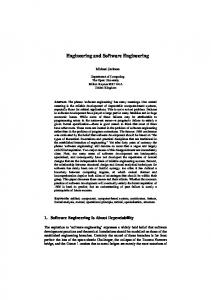
2.1 Introduction The emergence of the system-on-chip (SoC) era is creating many new challenges at all stages of the design process. At the systems level, engineers are reconsidering how designs are specified, partitioned and verified. Today, with systems and software engineers programming in C/C++ and their hardware counterparts working in hardware description languages such as VHDL and Verilog, problems arising from the use of different design languages, incompatible tools and fragmented tool flows are becoming common. C or C++ are the language choice for software algorithm and interface specifications because they provide the control and data abstractions necessary to develop compact and efficient system descriptions. Most designers are familiar with these languages and the large number of development tools associated with them. SystemC provides the necessary constructs to model system architecture including hardware timing, concurrency that is missing in standard C++. The C++ object-oriented programming language provides the ability to extend the language through classes, without adding new syntactic constructs as seen in figure 2-1. SystemC provides these necessary classes and allows designers to continue to use the familiar C++ language and development tools. The power of SystemC is that system designers, software engineers, and hardware designers can use it as a common language. The same benefits derived from the standardization of Verilog and VHDL in RTL design can now be achieved in the system design space with SystemC. In this chapter we will introduce SystemC and give a survey on its merits as a modeling language and the added value of using it as part of System on Chip (SoC) design flow.
Figure 2-1. SystemC Modeling Methodology
16
2.2 SystemC Constructs description In the following section we give some information related to the basic constructs of the SystemC that could help in understanding the SystemC code in the following chapters. 2.2.1
Modules
Modules are the basic building blocks within SystemC to partition a design. A module represents a block of hardware with well defined inputs, outputs and a well defined function. The configuration of the module, as seen in figure 2-2, is composed of processes that implement the module functionality, ports to interface with the external world and signals to facilitate communication between processes within the same module. port
Module
port Process Signals
port Process Figu Figure 2-2 Module configuration block
Figure 2-3 illustrates the contents of a module. Each module contains the following items: • • • • • •
Port declarations Internal signal variable declarations Internal data variable declarations Process declarations Member function declarations Module constructor
#include "systemc.h" SC_MODULE (module_name) { //Module port declarations //Signal variable declarations //Data variable declarations //Member function declarations //Method process declarations 17
//Module constructor SC_CTOR (module_name) { //Register processes //Declare sensitivity list } }; Figure 2-3. Module syntax declaration
2.2.2
Ports
Ports of a module represent the external interface that pass information to and from a module, and trigger actions within the module. Signals create connections between module ports allowing modules to communicate. A port can have three different modes of operation. • • •
Input Output InOut
An input port transfers data into a module. An output port transfers data out from a module, and an inout port transfers data both into and out of a module depending on the module operation. This is illustrated in figure 2-4.
sc_in
sc_out
Module Process
sc_in
sc_inout Process
Figure 2-4. Module Ports
Port declaration If the module is supposed to write a value to a port, you need to declare it as an output port or (sc_out). If the module is supposed to read a value from a port, you need to declare is as input port or (sc_in). If the module is supposed to read a value from an output port, you need to
18
declare it as an inout port or (sc_inout). Figure 2-5 gives a simple example for different port type declarations. #include "systemc.h" SC_MODULE (module_name) { //Module port declarations sc_in port name; sc_out port name; sc_inout port name; //Module constructor SC_CTOR (module_name) { //Register processes //Declare sensitivity list } }; Figure 2-5 Port syntax declaration
The macros sc_in, sc_out, sc_inout are used to declare the input, output and inout port respectively. SystemC also supports different data types for ports. Later in this chapter we will introduce the synthesizable data types. Here we concentrate just on how SystemC is used for synthesis. 2.2.3 Signals A signal connects the port of one module to the port of another module. The signal transfers data from one port to another as if the ports were directly connected. Also signals can be used for peer-to-peer communication between module processes as shown in figure 2-6. Input ports
Output ports
Module Process Signals
Input ports
Process
Figure 2-6. Module Signals
Signal declaration Signals can be easily declared within a module using the macro sc_signal after port declarations, as shown in figure 2-7. 19
#include "systemc.h" SC_MODULE (module_name) { //Module port declarations sc_in port name; sc_out port name; sc_inout port name; //Module signal declarations sc_signal signal1,signal2; //Module constructor SC_CTOR (module_name) { //Register processes //Declare sensitivity list } }; Figure 2-7 signal syntax declarations
As shown in the above figure the signal declaration also contains the signal data type, which similar to the port data types, will be described later in this chapter. The signal’s bit width is determined by its corresponding data type. 2.2.4 Reading and Writing Ports and Signals You can use the read and write methods or the assignment operator for reading and writing ports and signals as shown in figure 2-8. Using the assignment operator makes the code more concise and more like HDL code because you read and write directly to the ports. Using the read and write methods makes the code more readable. Read and write methods has an important advantage that can be used if you need an implicit type conversion because the type you are reading or writing is different from the port type (for example, if a port is a bool and you are reading or writing an int). #include "systemc.h" SC_MODULE (module_name) { //Module port declarations sc_in inport; sc_out outport; //Module signal declarations sc_signal signal1,signal2; ouport = signal1.read(); ouport.write(signal2); //Module constructor SC_CTOR (module_name) { 20
//Register processes //Declare sensitivity list } }; Figure 2-8. Reading and writing Signals and ports syntax declaration
2.2.5 Processes SystemC provides processes to implement the module functionality as mentioned before and to simulate the parallel behavior of hardware systems. Processes execute concurrently rather than sequentially as C++ functions. The code within a process, however, executes sequentially. Each process is sensitive to some signals, and a process is only called when any of the signals to which it is sensitive changes its value. A process contains a number of statements that implement the functionality of the process. These statements are executed sequentially as mentioned before until the end of the process is reached, or the process is suspended by one of the wait function calls. Process declaration Process declaration is similar to C++ member function declaration within module class. To differentiate the process declaration from normal member function declaration you need to register it within the module constructor as shown in figure 2-9. You can register multiple different processes, but it is an error to register more than one instance of the same process. To create multiple instances of the same process, enclose the process in a module and instantiate the module multiple times. To trigger the process execution you can use a way the similar to that of VHDL language; by using a sensitivity list that identifies which input ports and signals trigger execution of the code within a process. You can define level-sensitive inputs to specify combinational logic or edge-sensitive inputs to specify sequential logic. #include "systemc.h" SC_MODULE (module_name) { //Module port declarations sc_in port name; sc_out port name; sc_inout port name; //Module signal declarations sc_signal signal name; sc_signal signal1,signal2; void my_proc(); //Module constructor SC_CTOR (module_name) { //Register processes SC_METHOD(my_proc); 21
//Declare sensitivity list } }; Figure 2-9. Process syntax declaration
As shown in the previous figure, SyctemC macro SC_METHOD is used to register the process within the module. Figure 2-10 shows how a sensitivity list can be used to trigger the execution of the process. #include "systemc.h" SC_MODULE (module_name) { //Module port declarations sc_in port1; sc_out port2; //Module signal declarations sc_signal signal1,signal2; void my_proc(); //Module constructor SC_CTOR (module_name) { //Register processes SC_METHOD(my_proc); //Declare sensitivity list sensitive sc_inout)*/ }port_object; Figure 3-14 Port data structure
Data structure illustrated in figure 3-14 is designed for storing the data corresponding to each port in the design module. 1-type_name field indicates the type associated with the port. 2-name field indicates the name of the port. 3-index_start field indicates the starting value at which the logic vector starts in case of vector data types. 4-direction filed indicates the port direction such that: • • •
direction = 0 : indicates input port (sc_in). direction = 1 : indicates output port (sc_out). direction = 2 : indicates inout port (sc_inout).
//Data structure for the signal section typedef struct signaltype { char type_name[50]; char name[50]; }signal_object;
/*signal type name*/ /*signal name*/
Figure 3-15 Signal data structure
45
Data structure illustrated in figure 3-15 is designed for storing the data corresponding to each internal signal in the design module. 1-type_name field indicates the type associated with the signal. 2-name field indicates the name of the signal. //Data structure for the sensitivty list typedef struct sensitivity { char signal_name[50]; }sensitivety_object;
/*sensitivty signal name*/
Figure 3-16 Sensitivity list data structure
Data structure illustrated in figure 3-16 is designed for storing the data corresponding to each signal in the sensitivity list attached to each process. 1-Signal_name field indicates the name of the signal in the sensitivity list. //Data structure for the process typedef struct process { int process_type; /*Process type:combinational or sequential*/ int NofSen_signal; /*number of Senstivty signals*/ int NofRead_signal; /*Number of signal being read within process*/ char process_name[50]; /*process name*/ char sif_proc_body[5000]; sensitivety_object sen_array[10]; /*Sensitivty list*/ sensitivety_object read_array[10]; /*signal been read list*/ }process_object; Figure 3-17 Process type data structure
Data structure illustrated in figure 3-17 is designed for storing the data corresponding to each process in the designed module. 1-Process_type field indicates the kind of the process such that, • •
process type = 0 : indicates that we deal with a combinational process. process type = 1 : indicates we that deal with a sequential process.
2-NofSen_signal field indicates the number of the signals attached to the process in the sensitivity list. 3-NofRead_signal field indicates the number of signal being read within the process. 4-proces_name field indicates the name of the process. 5-sif_proc_body filed indicates the buffer on which the process statements are stored while parsing. 46
6-sen_array filed indicates the sensitivity list attached with the process. 7-read_Array field indicates the read array list attached with the process which contains all signals that have been read within the process. These data structures are filled while parsing the input SystemC code line by line then accessed while performing the conversion into VHDL and applying the Linting and reusability rules. Data structure for vector ports typedef struct vector_port { char vec_name [50]; int vec_len; }vector_object;
/*vector port name/* /*vector length/*
Figure 3-18 Vector port type data structure
Data structure illustrated in figure 3-18 is designed for storing the vector port name and consists of two fields: 1-vec_name indicates the vector port name. 2-vec_len indicates the vector length. 3.5.3 ScLint parsing rules 1-Accepting only the synthesizable subset mentioned in chapter 2 to produce synthesizable VHDL 2-Input SystemC file must contains the SC_MODULE declaration together with processes' definitions. 3-The module declaration consists of • Port declaration • Internal signal variable declaration • Process declaration • Member function declaration • Module constructor 4-Data types, supported in the port and signal variable declarations are those mentioned in the synthesizable data types mentioned in chapter 2. 5-Port and internal signal declaration syntax must take the following formats •
•
sc_in port_name,port_name; sc_in port_name;
6-All member functions declared in the module represents processes in the module. 7-ScLint does not support internal method declaration. 8-All member functions declared in the module declaration must be mentioned in the constructor declaration to avoid any errors. 47
9-The sensitivity signal declaration must be specified for each process in the constructor declaration. 10-Process definitions must be specified after module declaration. 11-ScLint tool supports two types of read/write to ports or signals which are: • • • •
address = into.read();// read method temp1 = address; // assignment outof.write(data_tmp); // write method temp2 = data_tmp; // assignment
12-Sclint tool doesn’t support Behavioral constructs like • • • •
For loop constructs While loop construct Do while loop constructs Case statements
13-Sclint tool doesn’t support thread types of process as they are included in the non synthesizable set. Thread types are: • •
Thread process. Clock threads process.
14-Process definition must not include any local data type declaration. Types must be declared in the module declaration. 15-ScLint doesn’t support arrays declaration. 16-ScLint supports the following types of operation: • • • • • • • •
Addition Subtraction Division Multiplication AND OR XOR NOT
17-ScLint doesn’t support nesting statements. 18-Sclint doesn’t support ternary expressions. 3.5.4. ScLint Linting algorithm
48
The ScLint tool is designed to work on the data structures mentioned above through applying the linting and reusability rules mentioned in this chapter on the input SystemC files. The linting algorithm is explained below. 1-Sclint parses the input SystemC file by applying the BNF rules mentioned in Appendix A, and stores the information gathered through parsing into the data structures mentioned above. 2-ScLint applies the reusability and linting rules mentioned in this chapter on the input SystemC code for syntax and semantic error checking. 3-ScLint tool produces the results in two different ways to support the different needs for users; • •
Output the warning/error messages on the command line mode for quick access. Document the resulting warning/error messages in the file called sclint.out
3.5.5 ScLint Error/Warning messages 1- Guideline: Start with port declaration, process declaration then module constructor declaration. 2- Error: Missing process and module constructor declarations. 2- Error: Missing module constructor declaration. 3- Error: Missing process declaration. 4- Error: Missing port declaration. 5- Error: Missing port and process declarations. 6- Error: Missing port and module constructor declarations. 7- Error: Constructor name miss match module name. 8- Error: Module has no sensitivity list. 9- Error: Mixed clock edges in the same module. 10- Error: Method not declared. 11- Error: Signal/Port should not be declared in the sensitivty list. 12- Error: Signal not declared. 13- Error: Class name miss match module name. 14- Error: Latch inferred for signal . 15- Error: Signal not declared in the sensitivty list. 16- Error: Port should not be declared on the right hand side of assignment statement. 17- Error: Boolean expression symbols mismatch for . 18- Error: Port name doesn't match any defined port. 19- Error: Signal/Port is not required in the sensitivity list of sequential process. 20- Error: Signal/Port declared in the sensitivty list not read in the process. 3.5.6. ScLint Linting results 49
In this section we will introduce the linting results produced by ScLint through some practical examples. This is illustrated in figures 3-19, 3-20, 3-12, 3-22, 3-23, 3-24, 3-25, 3-26 Example 1: Inferring a Positive-Edge-Triggered Flip-Flop \*--**************************************************\ \*--********** Linting violations messages ***********\ \*--Guiedline: Use name (clk) for clock signal*\ \*--Guiedline: Use name (rst) for reset signal*\ SC_MODULE(dff1) { sc_outout_q; sc_inin_data; sc_inclock; \*-- Warning: Module (dff1) has no signal declared *\ void do_dff_pos(); SC_CTOR(dff1){ SC_METHOD(do_dff_pos); sensitive"
::=
|
::=
SC_PORT
::=
SC_SIGNAL
::=
SYMBOL "," SYMBOL ";"
::=
SYMBOL | SYMBOL ""
::=
SYMBOL | NUMBER
::=
|
::=
VOID SYMBOL "(" ")" ";"
::=
CLOSE
::=
SC_CTOR "(" SYMBOL ")" "{"
::=
| ";" |
::=
|
::=
";"
::=
SC_METHOD "(" SYMBOL ")" ";"
::=
SESSITIVE
::=
|
::=
SENSYMBOL SYMBOL
|
116
::=
::=
VOID SYMBOL COLONCOLON SYMBOL "(" ")" " "{"
::=
stmtList
::=
|
::=
if_stmt | else_stmt | elseif_stmt | assign_stmtList | oper_stmtList | close_stmt
::=
::=
|
::=
|
::=
IF "(" ")"
::=
IF "(" ")" "{"
::=
SYMBOL "." READ "(" ")" COMP_SYM NUMBER | SYMBOL "." READ "(" ")" AND SYMBOL "." READ "(" ")" | SYMBOL "." READ "(" ")" OR SYMBOL "." READ "(" ")" | SYMBOL "." READ "(" ")" XOR SYMBOL "." READ "(" ")" | SYMBOL '.' READ "(" ")" AND SYMBOL | SYMBOL '.' READ "(" ")" OR SYMBOL | SYMBOL '.' READ "(" ")" XOR SYMBOL | SYMBOL AND SYMBOL "." READ "(" ")" | SYMBOL OR SYMBOL "." READ "(" ")" | SYMBOL XOR SYMBOL "." READ "(" ")" | SYMBOL COMP_SYM NUMBER | SYMBOL "." READ "(" ")" | "!" SYMBOL "." READ "(" ")" | SYMBOL AND SYMBOL | SYMBOL OR SYMBOL | SYMBOL XOR SYMBOL
::=
CLOSE | CLOSE
::=
CLOSE | CLOSE
::=
::=
|
else_stmtBody> ::=
|
::=
ELSE
::=
ELSE "{"
::=
ELSE IF "(" ")"
::=
ELSE IF "(" ")" "{"
::=
|
117
::=
CLOSE | CLOSE
::=
|
::=
CLOSE | CLOSE
::=
|
::=
SYMBOL "=" SYMBOL ";" | SYMBOL "=" "!" SYMBOL ";" | SYMBOL "=" NOT SYMBOL ";" | SYMBOL "=" "~" SYMBOL "." READ "(" ")" ";" | SYMBOL "=" NOT SYMBOL "." READ "(" ")" ";" | SYMBOL "=" SYMBOL "." READ "(" ")" ";" | SYMBOL "=" NUMBER ";" | SYMBOL "." WRITE "(" SYMBOL ")" ";" | SYMBOL "." WRITE "(" "!" SYMBOL ")" ";" | SYMBOL "." WRITE "(" NOT SYMBOL ")" ";" | SYMBOL "." WRITE "(" SYMBOL "." READ "(" ")" ")" ";" | SYMBOL "." WRITE "(" "!" SYMBOL "." READ "(" ")" ")" ";" | SYMBOL "." WRITE "(" NOT SYMBOL "." READ "(" ")" ")" ";" | SYMBOL "." WRITE "(" NUMBER ")" ";"
::=
CLOSE
::=
|
::=
| | | | | | |
::=
SYMBOL "=" SYMBOL "+" SYMBOL ";" | SYMBOL "=" SYMBOL "." READ "(" ")" "+" SYMBOL "." READ"(" ")" ";" | SYMBOL "=" SYMBOL "." READ "(" ")" "+" NUMBER | SYMBOL "=" SYMBOL "+" NUMBER | SYMBOL "=" NUMBER "+" SYMBOL "." READ "(" ")" | SYMBOL "=" NUMBER "+" SYMBOL ";" | SYMBOL "=" NUMBER "+" "+" ";" | SYMBOL "." WRITE "(" SYMBOL "+" SYMBOL ")" ";" | SYMBOL "." WRITE "(" SYMBOL '.' READ "(" ")" "+" SYMBOL "." READ "(" ")" ")" ";" | SYMBOL "." WRITE "(" SYMBOL "." READ "(" ")" "+" NUMBER ")" ";" | SYMBOL "." WRITE "(" SYMBOL "+" NUMBER ")" ";" | SYMBOL "." WRITE "(" NUMBER "+" SYMBOL "." READ "(" ")" ")" ";" | SYMBOL "." WRITE "(" NUMBER "+" SYMBOL ")" ";"
::=
SYMBOL "=" SYMBOL "-" SYMBOL ";" | SYMBOL "=" SYMBOL "." READ "(" ")" "-" SYMBOL "." READ"(" ")" ";" | SYMBOL "=" SYMBOL "." READ "(" ")" "-" NUMBER | SYMBOL "=" SYMBOL "-" NUMBER | SYMBOL "=" NUMBER "-" SYMBOL "." READ "(" ")" | SYMBOL "=" NUMBER "-" SYMBOL ";" | SYMBOL "=" NUMBER "-" "-" ";" | SYMBOL "." WRITE "(" SYMBOL "-" SYMBOL ")" ";" | SYMBOL "." WRITE "(" SYMBOL '.' READ "(" ")" "-" SYMBOL "." READ "(" ")" ")" ";" | SYMBOL "." WRITE "(" SYMBOL "." READ "(" ")" "-" NUMBER ")" ";" | SYMBOL "." WRITE "(" SYMBOL "-" NUMBER ")" ";" | SYMBOL "." WRITE "(" NUMBER "-" SYMBOL "." READ "(" ")" ")" ";" |
118
SYMBOL "." WRITE "(" NUMBER "-" SYMBOL ")" ";" ::=
SYMBOL "=" SYMBOL "/" SYMBOL ";" | SYMBOL "=" SYMBOL "." READ "(" ")" "/" SYMBOL "." READ"(" ")" ";" | SYMBOL "=" SYMBOL "." READ "(" ")" "/" NUMBER | SYMBOL "=" SYMBOL "/" NUMBER | SYMBOL "=" NUMBER "/" SYMBOL "." READ "(" ")" | SYMBOL "=" NUMBER "/" SYMBOL ";" | SYMBOL "." WRITE "(" SYMBOL "/" SYMBOL ")" ";" | SYMBOL "." WRITE "(" SYMBOL "." READ "(" ")" "/" NUMBER ")" ";" | SYMBOL "." WRITE "(" NUMBER "/" SYMBOL "." READ "(" ")" ")" ";" | SYMBOL "." WRITE "(" SYMBOL "." READ "(" ")" "/" SYMBOL "." READ "(" ")" ")" ";" | SYMBOL "." WRITE "(" SYMBOL "/" NUMBER ")" ';" | SYMBOL "." WRITE "(" NUMBER "/" SYMBOL ")" ";"
::=
SYMBOL "=" SYMBOL "*" SYMBOL ";" | SYMBOL "=" SYMBOL "." READ "(" ")" "*" SYMBOL "." READ"(" ")" ";" SYMBOL "=" SYMBOL "." READ "(" ")" "*" NUMBER | SYMBOL "=" SYMBOL "*" NUMBER | SYMBOL "=" NUMBER "*" SYMBOL "." READ "(" ")" | SYMBOL "=" NUMBER "*" SYMBOL ";" | SYMBOL "." WRITE "(" SYMBOL "*" SYMBOL ")" ";" | SYMBOL "." WRITE "(" SYMBOL "." READ "(" ")" "*" NUMBER ")" ";" | SYMBOL "." WRITE "(" NUMBER "*" SYMBOL "." READ "(" ")" ")" ";" | SYMBOL "." WRITE "(" SYMBOL "." READ "(" ")" "*" SYMBOL "." READ "(" ")" ")" ";" | SYMBOL "." WRITE "(" SYMBOL "*" NUMBER ")" ';" | SYMBOL "." WRITE "(" NUMBER "*" SYMBOL ")" ";"
::=
SYMBOL "=" SYMBOL AND SYMBOL ";" | SYMBOL "=" SYMBOL "." READ "(" ")" AND SYMBOL "." READ "(" ")" ";" | SYMBOL "=" SYMBOL "." READ "(" ")" AND NUMBER ";" | SYMBOL "=" SYMBOL AND NUMBER ";" | SYMBOL "=" NUMBER AND SYMBOL "." READ "(" ")" ";" | SYMBOL "=" NUMBER AND SYMBOL ";" | SYMBOL "." WRITE "(" SYMBOL AND SYMBOL ")" ";" | SYMBOL "." WRITE "(" SYMBOL "." READ "(" ")" AND SYMBOL "." READ "(" ")" ")" ";" | SYMBOL "." WRITE "(" SYMBOL "." READ "(" ")" AND NUMBER ")" ";" | SYMBOL "." WRITE "(" SYMBOL AND NUMBER ")" ";" | SYMBOL "." WRITE "(" NUMBER AND SYMBOL "." READ "(" ")" ")" ";" | SYMBOL "." WRITE "(" NUMBER AND SYMBOL ")" ";"
::=
SYMBOL "=" SYMBOL OR SYMBOL ";" | SYMBOL "=" SYMBOL "." READ "(" ")" OR SYMBOL "." READ "(" ")" ";" | SYMBOL "=" SYMBOL "." READ "(" ")" OR NUMBER ";" | SYMBOL "=" SYMBOL OR NUMBER ";" | SYMBOL "=" NUMBER OR SYMBOL "." READ "(" ")" ";" | SYMBOL "=" NUMBER OR SYMBOL ";" | SYMBOL "." WRITE "(" SYMBOL OR SYMBOL ")" ";" | SYMBOL "." WRITE "(" SYMBOL "." READ "(" ")" OR SYMBOL "." READ "(" ")" ")" ";" | SYMBOL "." WRITE "(" SYMBOL "." READ "(" ")" OR NUMBER ")" ";" | SYMBOL "." WRITE "(" SYMBOL OR NUMBER ")" ";" | SYMBOL "." WRITE "(" NUMBER OR SYMBOL "." READ "(" ")" ")" ";" | SYMBOL "." WRITE "(" NUMBER OR SYMBOL ")" ";" |
::=
SYMBOL "=" SYMBOL XOR SYMBOL ";" | SYMBOL "=" SYMBOL "." READ "(" ")" XOR SYMBOL "." READ "(" ")" ";" | SYMBOL "=" SYMBOL "." READ "(" ")" XOR NUMBER ";" | SYMBOL "=" SYMBOL XOR NUMBER ";" | SYMBOL "=" NUMBER XOR SYMBOL "." READ "(" ")" ";" | SYMBOL "=" NUMBER XOR SYMBOL ";" | SYMBOL "." WRITE "(" SYMBOL XOR SYMBOL ")" ";" | SYMBOL "." WRITE "(" SYMBOL "." READ "(" ")" XOR SYMBOL "." READ "(" ")" ")" ";" | SYMBOL "." WRITE "(" SYMBOL "." READ "(" ")" XOR NUMBER ")" ";" | SYMBOL "." WRITE "(" SYMBOL XOR NUMBER ")" ";" | SYMBOL "." WRITE "(" NUMBER XOR SYMBOL "." READ "(" ")" ")" ";" | SYMBOL "." WRITE "(" NUMBER XOR SYMBOL ")" ";"
119
Appendix B B.1 SCMapper 8-bit adder Code Listing SycTemC Input before Mapping SC_MODULE(adder) { sc_in a; sc_in b; sc_in z; sc_out c; sc_out s;
/*8-bit operand*/ /*8-bit operand*/ /*cin*/ /*SUM*/ /*cout*/
void onetwothree (); SC_CTOR(adder) { SC_METHOD(onetwothree); sensitive_pos