AbstractâActive Learning Method (ALM) is one of the powerful tools in soft computing that is inspired by human brain capabilities in processing complicated ...
> REPLACE THIS LINE WITH YOUR PAPER IDENTIFICATION NUMBER (DOUBLE-CLICK HERE TO EDIT)
REPLACE THIS LINE WITH YOUR PAPER IDENTIFICATION NUMBER (DOUBLE-CLICK HERE TO EDIT) < transfer. Pipeline implementation by Firouzi [19] suffers from digital computing problems such as overflow and finite precision. Tarkhan’s analog implementation, however, suffers from high power consumption and high complexity of each IDS plane [20]. Memristor is a nonlinear passive two-terminal electrical element whose resistance is controlled by voltage and can act as a memory resistor. Because of the compatibility of IDS planes with memristor-crossbar structure, the implementation of IDS planes on this structure is efficient and of low cost. For this reason, Merrikh-bayat proposed the first memristor crossbar hardware implementation of IDS plane [21] and then, a more efficient implementation was proposed by Esmaili [22]; however, both implementations suffer from large hardware problem. These hardware implementations suffer from large amount of memory required to store the information of IDS planes and consequently higher power consumption. For instance, for an IDS plane, memory cells (memristors) are required, where is the resolution of the IDS plane. This large number of memristors are enough to implement the information of only one IDS plane, and as the number of inputs or their fuzzy partitioning increases, the number of IDS planes increases inevitably. In addition, the hardware required to implement IDS operator and inference engine also add to the complexity of the overall hardware implementation. In our proposed algorithm, a novel approach to describe IDS planes is employed, which eliminates the computational complexity of IDS operator and requires only memory cells (memristors) for each IDS plane. This results in significant reduction in the hardware complexity of the memory unit from ) to ), where is the resolution of an IDS plane on each of its axis. In our proposed algorithm three rows of memory cells with resolution of memristors are assumed, two of which store the upper-bound and the lower-bound of the input-output relationship in an IDS plane. The difference between these two rows (or vectors) is inversely proportional to the degree of belief by which the associated input value is observed, and the last row keeps the values of the output. In the learning phase, when a new training sample is observed, each element of these three vectors will be updated by applying a coefficient of their distance to the new observed sample. Following are justifications of our proposed algorithm: 1) The large number of required memory cells to store the information of IDS planes as well as partial usage of the whole memory in traditional approaches reveals the need for a novel approach, particularly in the way IDS planes are described. 2) The large hardware required to implement IDS planes and IDS operator should be optimized to make it suitable for real-time applications. 3) Hardware should be reduced in size and complexity to optimize the power consumption.
2
4) In traditional approaches, there was a need for a diode with low inverse current to be serried with memristor and to reduce the feedback effect. The proposed approach eliminates this need. 5) In the traditional approaches, the memristive implementation was based on approximated mathematical equations; whereas, the proposed hardware is implemented with accurate mathematical equations. Therefore the proposed algorithm enjoys a significant reduction in the large amount of required memory and in the computational complexity of the IDS operator. Due to the analog mechanism of our proposed algorithm, it out performs digital implementations in terms of learning and test speed. In addition, the proposed hardware is implementable with considerably lower computational complexity. The remainder of this paper is organized as follows. The main concepts of ALM and IDS operator are reviewed in section 2, followed by a brief description of the forth fundamental electrical element called memristor in section 3. Section 4 illustrates our proposed algorithm and its memristorcrossbar hardware implementation is presented in section 5. The evaluation of our proposed algorithm is presented in section 6. Eventually section 7 concludes our paper and provides suggestions for future work. II.
ACTIVE LEARNING METHOD (ALM)
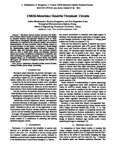
Processes and computations in the human brain are believed to be qualitative and imprecise in their essence. This observation has led to a research field called soft computing, which deals with uncertainty and simulates the human brain. Among those, fuzzy systems, which is inspired by human brain capabilities, can be employed as a tool to deal with uncertainty and to provide stability in real-world problems. ALM has adopted a fuzzy approach and has its basis in hypotheses which claim that humans interpret their surrounding environment in an inexact manner and rather than dealing with quantities and numbers, a general characteristic of the environment is learned. Facing a new problem, humans tend to avoid delving into details; instead, a general understanding of the problem is preferred and, if required, minor problems are overcome first. Therefore, in dealing with complicated problems, humans first attempt to find simpler or familiar concepts and then by discovering logical connections among these concepts, obtain an inexact definition and a general understanding of the problem without much effort. ALM is an adaptive fuzzy learning method that obtains a clearer understanding of the original problem by splitting a complicated problem into several simpler ones. ALM approach to splitting a MISO system into several SISO subsystems is illustrated in Fig. 1. X1 X2 . . . Xn
MISO
Y
X1
SISO
X2 . . . Xn
SISO
SISO
Inferential Process
Y
X1
IDS
X2 . . . Xn
IDS
Inferential Process (Rules Combination)
Y
IDS
Fig. 1. ALM approach to splitting a MISO system into several SISO subsystems. For each SISO subsystem, an IDS unit is allocated to extract the
> REPLACE THIS LINE WITH YOUR PAPER IDENTIFICATION NUMBER (DOUBLE-CLICK HERE TO EDIT) < features. All features are then aggregated in the inference engine to approximate the output.
ALM has two main steps. The first step is updating IDS planes when training samples are observed and the last step in which inference process is done. These steps are discussed in the following subsections. A. Ink Drop Spread (IDS) Operator The heart of ALM is the IDS operator which somehow models fuzzy interpolation. Despite traditional learning algorithms in which system behavior is represented by complicated mathematical equations, ALM tries to simulate human brain functionality by providing a qualitative and behavioral description of the system. In ALM, the imprecise and fuzzy characteristics of the human brain in learning from events is modeled by IDS operator. The function of the IDS operator is inspired by the fact that experiences in the data space are continuous in essence. In other words, the space of learning is not confined to those observed samples; moreover, in the vicinity of an observed sample, the learned features are still valid, though, probably with less certainty as we move away from that observed sample. If the domain of all inputs and output are quantized, then an IDS plane associated with a SISO subsystem is a gridded plane that depicts the projected samples of input and output for a specific domain of variation of other inputs. The effect that the IDS operator has on an observed sample is analogous to instilling an ink drop on the coordinate of that sample. The IDS operator is applied to all observed samples of input and output on the IDS plane. Each IDS unit is comprised of two main parts. A 2-D plane that captures the relationship and the Feature Extracting Unit that extracts useful information from the formed pattern on the IDS plane as shown in Fig. 2.
Xi – Y Plane (IDSi)
Ymax Features:
Xi min
Xi max
Feature Extracting Unit
Narrow Path & Spread
Ymin
Fig. 2. The structure of an IDS unit. Initially the IDS plane is white (empty) and when a new sample is observed the associated ink drop will spread on the IDS plan, as an ink drop spreads on a sheet of paper. Narrow Path and Spread are two features that will be extracted from the pattern formed on the IDS plane by feature extraction unit. These features are then fed to the inference engine. In this figure a pyramid membership function is assumed.
For simplicity the number of IDS planes is assumed to be equal to the number of inputs (no partitioning is performed on inputs domain). When a training sample is observed, where , and is the size of the training dataset. The plane, which is associated with the relationship between the output and the th input, is updated according to the projection of that sample on this IDS plane. For instance, assume two ( ) distinct samples and
3
( ) are observed. In this twoinput single-output system, two white (empty) IDS planes and are assumed. As shown in Fig. 3 ( ) ( ) and ( ) spread on the plane. Meanwhile, ( ) and spread on the plane. The membership function for spreading ink drops can be considered Gaussian, Pyramid, Conic or any convex 3-D shape that decreases as the distance to its centers increases. In Fig. 3 with pyramid membership function, as ink drops spread, overlapped patterns become increasingly darker. These darker regions increase our belief in those regions of the input space. X1 – Y Plane (IDS1)
Ymax
X2 – Y Plane (IDS2)
Ymax
X1 max X2 min
X1 min (-5,5)
(4,4)
Ymin (a)
X2 max
(-1,4)
(4,5)
Ymin (b)
Fig. 3. An example of 2-input single-output system with pyramid ( ) membership function and two training samples ) , ( . (a) The plane associated with relationship where the projection of two training samples is spread ( ) ( ) , . (b) The plane associated with relationship where the projection of two training ( ) ( ) samples is spread , . As it can be seen, the overlapped regions have become increasingly darker. The increased darkness of some grids signifies the correctness and support of other observed samples. The overlapping ink drops somehow models fuzzy interpolation.
Fig. 4 shows a formed pattern on an IDS plane when all training samples have been observed and their associated ink drops have spread. The method to find the values of Narrow Path and Spread in the position of a candidate point are shown on the figure. The Narrow Path function for the formed pattern has been shown with red color and the inverse of Spread around the Narrow Path reveals the degree of certainty regarding the occurrence of that observation. One of the advantages of ALM is that only one epoch is sufficient to learn the training set and no initialization is required. The order of observing training samples does not affect the final result and the algorithm gradually learns through interaction with the system. When a new training sample is observed only local regions, rather than the whole plane, are updated[11]. It is worth mentioning that the radius, an ink drop is permitted to spread, is an important parameter that affects the performance, convergence speed and output error. This user-defined parameter is inversely correlated with the size of the training set and the density of samples. This parameter is defined according to the resolution of the IDS plane as well as the density and distribution of training samples. In the original version of the ALM this parameter is chosen through an iterative trial and error approach which is time consuming. In the figure provided, it can be seen that the IDS plane can be
> REPLACE THIS LINE WITH YOUR PAPER IDENTIFICATION NUMBER (DOUBLE-CLICK HERE TO EDIT) < treated as a 2-D memory unit, in which each cell stores the darkness of the associated grid on the IDS plane. Y
Where each input is in have:
dimensional space and we will
,
Function of Narrow Path * Narrow Path at point x= Xi
)2(
The first step of ALM is quantizing the input and output domains in each IDS plane. For simplification, quantization levels for both input and output can be the same and equal to . By this choice the resolution of the IDS plane is , where . Therefore, we have:
* Spread at point x= Xi * Y
( ⌊ Xi*
4
)
⌋
)3(
Xi
Fig. 4. An example of a typical pattern formed on plane when the IDS operator is applied to all training samples on jth plane. The Narrow Path function is shown with red color and the method to find the Narrow Path and Spread in the position of a candidate point is shown on the figure. The inverse of Spread around an input value reveals the degree of belief we have regarding the occurrence of that observation.
B. Inference Engine in ALM After the IDS operator has been applied to all IDS planes and the Narrow Path and Spread for all IDS planes have been extracted, these features are then fed to the inference engine of the ALM. The Narrow Path function in the reveals the relationship between the output and the input and the value of Spread in this plane, compared to spread in other planes, is an indication of the importance of the input in approximating the output. As shown in Fig. 4, the Spread in some input domains is wider than that of other domains. Wide Spread in some input domains, implies that in those input domains the output is more affected by other inputs rather than , because the output has varied a lot, while the input held almost the same value. This is the justification for how a MISO can be approximated by several SISO subsystems in ALM. If the Spread is wide for all input domains on an IDS plane, fuzzy partitioning the universe of discourse of other inputs is proposed. In this case, for each partition a separate IDS plane is required and by splitting the input domain more knowledge can be extracted from IDS planes, which leads to lower approximation error. It should be noted that if the datasets is small, excessive partitioning the input domain will result in high approximation error. Various approaches have been proposed to find the Narrow Path including maximum operator and averaging operator. In order to measure the Spread, the width of the ink drop spread around each point can be employed. The following is an approach proposed in[11]. It should be mentioned that because of the fuzzy and inexact nature of the IDS operator in ALM, different approaches for extracting these features do not vary that much in final results and the selection among different approaches depends on the hardware implementation and processing speed considerations. For the dataset that contains training samples: )1(
{ ⌊
⌋
)4( { Where and is the number of IDS planes. The quantized values are as follows:
)5( )6( If is a projected point to the space and we assume that its darkness is indicated by and its membership function is a Gaussian with maximum of one and appropriate variance, then observing such a sample entails updating the grid on the plane as follows:
)7( ,
)8(
Where indicated the radius of ink drop spread and is the shape of ink drop spread. With regard to definitions of Narrow Path and Spread, these two features are calculated as follows: 𝜓
{
∑
∑
}
)9(
)10( Where 𝜓 and are Narrow Path and Spread on the plane respectively. The first equation implies that the Narrow Path value on the plane for any given quantized input is , if the sum of the grids darkness values above the grid is approximately equal to the sum of the grids darkness values below the . The second equation implies that the
> REPLACE THIS LINE WITH YOUR PAPER IDENTIFICATION NUMBER (DOUBLE-CLICK HERE TO EDIT) < Spread value on the plane for any given quantized input is proportional to the effective width of the formed pattern on the column of grids on the coordination of . In this equation, the parameter indicated the minimum acceptable darkness of a grid on the IDS plane to measure the Spread, and is defined by the user. When a new test sample is observed, , where is the dimension of the test sample, the Narrow Path and Spread values for this sample from all IDS planes are extracted and then summed to approximate the output as follows: ∑
𝜓
)11(
5
and Spread, from all IDS planes are aggregated to approximate the output. The number of fuzzy rules in inference unit is equal to the number of IDS planes.
Start
Gather data samples
Spread all ink drops associated with training samples
Extract Narrow Path & Spread
∑
)12( ( )
Where is the number of IDS planes (if no partitioning is performed, also the number of inputs). As it can be seen, the inference in ALM is done by weighted sum of Narrow Paths where is the weight associated with the Narrow Path, which is the normalized value of Spread inverse or any descending function (the wider the Spread in plane the lower we believe in the Narrow Path of th plane and vice versa). For those values of whose grid on the IDS plane is white, 𝜓 and values are assumed to be equal to ⁄ . Fig. 5 shows the flowchart of ALM algorithm. In the first step of this algorithm for those IDS planes where data samples are sparse, data sampling is performed intelligently. Initially no partitioning on inputs domain is performed. After IDS operator is applied and Narrow Path and Spread are extracted, the most effective inputs will be identified. The model is then built and if the approximation error is within a user-defined range, the algorithm stops; otherwise, inputs domain partitioning will be performed. Even if by partitioning the inputs domain, samples on IDS planes are still sparse and the algorithm is not successful to decrease the error, the algorithm returns to the first step and samples more data and rebuilds a new model to decrease the error. In the next step, if the Spread in an IDS plane is greater than a user-defined threshold, the algorithm intelligently identifies that IDS plane and more data sampling is performed for that particular IDS plane. Various methods for partitioning the input domain have been proposed, one option is to double the partitioning in each step[11]. In Aristotle’s logic, in order to enhance knowledge, it is proposed that more details should be extracted, this is in stark contrast with ALM which is inspired by human brain functionality. When faced with a new learning situation, the human brain tends to discard details and learn the overall behavior. In ALM, if desirable and sufficient knowledge is not achieved, then by splitting the original system into some simpler subsystems, more knowledge is aimed to achieved within each SISO subsystem, because each of which only deals with a particular domain of inputs. Eventually, in the inference unit of ALM, the extracted features, Narrow Path
Rank inputs by using Spread & aggregate the effective inputs (Construct Model) NO NO Error >T1 YES YES Partition inputs domain
Include next effective variable
Monitor plane spreads
YES YES
Spread>T2 NO NO End
Fig. 5. ALM flowchart. In this algorithm the most effective inputs in approximating the output are intelligently identified and the algorithm tries to build a model with the minimum complexity and the number of inputs. In this flowchart, is the desirable error threshold and is the threshold that defines the minimum acceptable data density on IDS planes.
III.
MEMRISTOR
In addition to the three previously known fundamental electrical elements: resistor, capacitor and inducer, in 1971, Leon Chua mathematically proved and introduced the fourth circuit element relating the electrical charge with the magnetic flux[23],[24]. This element named Memristor as a combination of “Memory” and “Resistor”. Prior to 2008 no successful implementation of this element was reported, this was mainly due to the fact that the memristive characteristic is only observable in Nano scale. In mid-2008, in HP research laboratory the first memristor was successfully realized [25]. Memristor has various applications such as implementing nonvolatile RAM [26], spiking neural networks[27] and human learning algorithms[28],[29], digital circuits[30],[31], programmable analogue circuits[32],[33],[34],[35], pattern recognition and signal processing[36]. Because of the
> REPLACE THIS LINE WITH YOUR PAPER IDENTIFICATION NUMBER (DOUBLE-CLICK HERE TO EDIT) < powerful implementation capabilities, low power consumption and stability of stored data even without power, memristor has received considerable attention[37]. Fig. 6 shows the relationships between different variables in electrical circuits.
dq=i dt Capacitor q
Resistor
Inductor i
v
Missing link
d = v dt Memristor
Fig. 6. Four fundamental elements of electrical circuits: resistor, capacitor, inducer and memristor. Memristor is the fourth fundamental element and the missing link which relates electrical charge with magnetic flux. Theoretically, the value of a memristors remains unchanged if no current passes through it. Like capacitors, memristor does not require refreshment to preserve its value.
A. Physical structure and equations Memristor is a passive two-terminal element which relates the electrical charge with magnetic flux as follows: (13) Equation (13) can also be written as follows, which indicates that the unit of memristance is Ohm. ⁄ (14)
⁄
Memristor can behave as a dynamic resistor whose resistance changes with respect to the voltage applied to or current passes through its terminals. If the characteristic of the memristor is considered linear, it behaves as a simple resistor with resistance . Fig. 7 shows the physical and circuit model of the first memristor realized by HP [25]. As it can be seen from Fig. 7, memristor is comprised of a very thin layer of Titanium Dioxide ( ) with width sandwiched between two platinum ( ) contacts. The semiconductor itself is comprised of a doped and an undoped regions. The width of doped region is and the resistance of this region is lower than the other region. The variable width of the doped region makes the memristor a dynamic resistor. Device Structure
Equivalent Circuit
Symbol
D
Undoped
Doped
Ron
IM W
Roff
RM
+ VM (a)
(b)
(c)
Fig. 7. (a) The structure of a memristor is comprised of two regions; the doped region (low resistance ) and undoped region (high resistance ). By applying voltage with appropriate polarity and amplitude the border between these regions displaces. (b) Circuit equivalent of memristor. (c) memristor symbol.
6
By applying voltage to the two terminals of a memristor, the border of two regions displaces and this causes the total resistance to change. The resistance value changes between two extremes; and . When the applied voltage amplitude is so that the doped region extends to the full width ( ) the memristance tends to reach its minimum value ( and inversely when the applied voltage amplitude makes the undoped region extends to the full width ( ) the memristance tends to reach its maximum value . In the mathematical model of memristor proposed in [25], as in (15) and (16), the electrical field in the memristor is assumed to be uniform. (15) (16) Where is the initial width of doped region , is the average ion mobility and is the net electrical charge passing through the element. These equations also reveal that the passing electrical current in one direction increases the memristance; whereas, the opposite direction of current decreases the memristance and if no current passes through the element, the memristance remains constant and behaves like a simple resistor. Thus, polarity and amplitude of the voltage signal as well as the duration of this signal are the main parameters affecting the memristance. In order to read the value of a memristor, it is sufficient to apply a current signal with amplitude less than a threshold for a short period of time and read the voltage over the terminals. Various algorithms and computational frameworks for simulating the computational capabilities of the neural system of living organisms have been proposed. Almost all these frameworks suffer from a major drawback that is the lack of compatibility between hardware and the nature of the problems in hand such as implementation of Neuromorphic systems on FPGAs [38]. The main focus, though, is on hardware implementation which is not efficient that makes the large scale implementation of these algorithms infeasible. This problem has been resolved to some extent since the realization of memristor which complies with the synaptic behavior of a biological neuron and can be implemented in small size. Numerous studies have been shifted to this kind of implementations. In the next section the implementation of the IDS plane on the memristor crossbar structure will be presented. B. Memristor crossbar implementation of IDS plane A memristor crossbar is comprised of a series of horizontal wires passing over vertical ones, and at each intersection, a memristor is connected so that by applying proper voltage over any pair of vertical and horizontal wires, the memristor at that intersection can be accessed. In fact, the memristor crossbar is analogous to an array of analogue memory cells. The analogue values are stored as memristance of memristors.
> REPLACE THIS LINE WITH YOUR PAPER IDENTIFICATION NUMBER (DOUBLE-CLICK HERE TO EDIT)
REPLACE THIS LINE WITH YOUR PAPER IDENTIFICATION NUMBER (DOUBLE-CLICK HERE TO EDIT)
REPLACE THIS LINE WITH YOUR PAPER IDENTIFICATION NUMBER (DOUBLE-CLICK HERE TO EDIT)
REPLACE THIS LINE WITH YOUR PAPER IDENTIFICATION NUMBER (DOUBLE-CLICK HERE TO EDIT) < VDD
Sel 1
+
(b-1)
OP-Stage 5
OP-Stage 4
VC U
VX
t UB
i
R1
Connector RF2
P 1
UB Learning Unit
OP-Stage 2
Demultiplexer
(a-1)
R
OP-Stage 1
g UB
+
...
CUB
R MU . . . UB Storage Unit
CLB
R ML . . .
-
“V Bias”
g LB
+
R
(c-1)
+
R
i
RS
R
RS
R
RS R
Spread Computing Unit
z UB i
“V Bias”
RF1
-
...
R
i
RF1
LB Storage Unit
(a-2)
R
R
m
m Address
Rb
Yxi
R1
-
“V Read”
P
-
UB
“V Train”
+
P
OP-Stage 3
Rb
C
+
0
10
z LB
+
+
SP
RS i
-
OP-Stage 1
Demultiplexer
Address
OP-Stage 2
m
R
LB Learning Unit m
P
0
LB
R1 i
P
Rb
R1
Y xi
“V Train”
R
Rb OP-Stage 3
-
+
(b-2)
C
t LB
+
P
VCL
-
VX
+
Connector “V Read”
R RF2
-
1
Sel 1
OP-Stage 5
OP-Stage 4
VDD Fig. 12. The proposed hardware implementation for storing, learning and spread computing processes. Circuit (a) of the proposed hardware is responsible for storing the upper-bound and the lower-bound of the input and circuit (b) performs the process of learning and storing in memristors. Circuit (c) is also known as Spread Computing Unit that measures the spread of an input point. In this circuit parameter ⍺ in (21) and (22) equals to .
, the initial voltage of node
is equal to
. By
decreasing the resistance of toward , if , then the initial voltage of node becomes zero. In Fig. 12(b-2) if and if the initial value of all is assumed to be equal to , then the initial
voltage of node is equal to zero. By increasing the resistance of toward , then the initial voltage of node becomes . Therefore, all memristors of the first and second rows are initialized to and respectively. Note the polarity and the connection of memristors in Fig. 12.
> REPLACE THIS LINE WITH YOUR PAPER IDENTIFICATION NUMBER (DOUBLE-CLICK HERE TO EDIT)
REPLACE THIS LINE WITH YOUR PAPER IDENTIFICATION NUMBER (DOUBLE-CLICK HERE TO EDIT) < In Fig. 13, the Narrow Path Extraction Circuit is shown. In the proposed circuit, the voltage of the output node should be initialized to the half of the resolution of the IDS plane. This entails that the voltage of the node should be equal ⁄ . In the Fig. 13(b-3), if to , and
and we assume that the
initial resistance of
is equal to , then the voltage of ⁄ . Increasing or decreasing the node is equal to resistance of increases or decreases the voltage of node respectively. Fig. 14 shows the Connector Circuit which is comprised of Flip-Flops, AND gates, Triangular signal generator, Multiplexers and negating Op-Amp circuits. The latter circuit receives a triangular signal with constant frequency and amplitude, which is stored in a capacitor, and then generates appropriate squared signals required in the learning phase. The width of squared signals for central memristor and m signals of its neighbors (for simplicity ) are adjusted in this circuit. Fig. 15 shows the signals generated in the Connector Circuit. These signals are selected based on the polarity of the capacitor and are applied to memristors in the learning phase. B. Learning Phase The learning phase in the proposed hardware is as follows. When a new training sample is observed, its distance to all elements of three describing vectors are calculated and then multiplied by learning rates 𝛼 and 𝛼 to update three describing vectors, as shown in Fig. 10. The process involved in reading memristors values and updating them is the same for each describing vector. In order to read memristance of a memristor, signal ̅ is activated and as a result, the MOSFET switch is turned on. By applying appropriate voltage signal to the targeted memristor by address line of the demultiplexer, the reading process will be started. Voltage reaches the output node with amplification gain . The output of each Op-Amp stage is as follows: 𝛼
(28)
For voltage y proportional to each sample, proportional voltage should be applied, which is computed as follows: (29)
(
𝛼
)
(30)
(31)
12
If the MOSFET switch ̅ is activated, the capacitor holds the voltage . In the next step, by activating the MOSFET switch , the stored voltage in the capacitor is transferred to Connector Circuit. Based on user-defined variance , which defines the number of neighbor memristors to be involved in the learning process when the targeted memristor is chosen to be updated, the appropriate output signals are applied to these memristors. The Voltage obtained in (31) is equivalent to (21), where is proportional to the output value of training sample and it is proportional to which is itself proportional to the value stored in the memristor array . This equivalency is shown in (33). ⏞ ⍺
𝛼 [
]
(33)
As shown in (33), the output voltage stored in the capacitor is proportional to the distance. Thus the proposed circuit implements the algorithm with acceptable approximation (for two other vectors we do the same as (33)). C. Modeling or Test Phase In the previous subsection the learning phase of the proposed hardware was presented. In this subsection, the required hardware for the test phase, when it should model previously unseen test samples, is proposed. In order to perform the inference in the proposed algorithm, it is first required that the Narrow Path and Spread values in the coordination of the test sample be extracted from three describing vectors of each IDS plane. The proposed circuit for extracting Spread is shown in Fig. 12(c-1). We have: (34) The proposed hardware acts like a differential amplifier that amplifies the difference between and . In Fig. 13(b-2) the output voltage is proportional to Narrow Path for given coordination of the test sample. These values are used in the inference engine of ALM. In the test phase, for each input value , Narrow Path and Spread are available for any time. For each input , only the associated features are extracted and the computation and storage of all values of Narrow Path and Spread are not required. The proposed circuit performs well only when appropriate signals are applied to the memristor circuit, so the value of memristor changes in the desirable direction with desirable amplitude. Therefore, in order to read each memristor, it is sufficient to apply voltage to the column of the memristor associated with test sample and apply appropriate squared signal to its row and read the output voltage. The frequency of such a signal should be high and its width should be so negligible that by applying it to the memristor, it acts like a resistor and its memristance can be read without any change. In order to write a new value in a resistor the appropriate squared signal should have two main
> REPLACE THIS LINE WITH YOUR PAPER IDENTIFICATION NUMBER (DOUBLE-CLICK HERE TO EDIT) < characteristics; the amplitude of such a signal should be greater than the threshold of memristor and it should be wide enough to change the memristance. For higher precision more quantization levels are required. This is achieved by adding more memristor to the Storage circuit. Table I Compares the circuit complexity of our proposed algorithm (Fast ALM) and ALM[21]. TABLE I THE COMPARISON OF CIRCUIT COMPLEXITY OF OUR PROPOSED ALGORITHM (FAST ALM) AND ALM[21]. THE COMPARISON IS DRAWN FOR A SINGLEINPUT SINGLE -OUTPUT SYSTEM WITHOUT PARTITIONING THE INPUT DOMAIN (ONE IDS PLANE). Elements
ALM in [21]
Opamp Memristor
Fast ALM 28 3*
2*
VI.
13
SIMULATION
In this section the functionality and performance of our proposed algorithm is evaluated on various applications. Function approximation and classification are two problems considered in this section. All simulations are performed in MATLAB 2013 on Core i5 processor, 2.4GHz, 4GB RAM. The quantization levels in all simulations are considered . A. Function Approximation In this section, the performance of Fast ALM algorithm and its hardware implementation is evaluated on function approximation problem. Two 2-input single-output functions are considered as follows. (35)
Unlike ALM, in Fast ALM the number of Op-Amps is independent of the resolution of the IDS plane. Table I Also reveals that in terms of size and power consumption our proposed hardware is considerably more efficient than the hardware proposed in [21]. Furthermore, the proposed hardware has low circuit complexity and faster process time without compromising the precision. Another advantage of our proposed hardware compared to traditional hardware is that the need for so many multipliers and adders is satisfied to a great extent. It should be mentioned that in this comparison only shared circuit elements in both hardware implementations have been taken into account and those circuit elements such as Flip-Flops, AND gates, etc. of each specific hardware are excluded.
√
(
)
(
)
(36)
Fig. 16 and 17 show two functions as defined in (35) and (36). In this proposed hardware the period of the input triangular signal in PWM generator is 10milliseconds ( ). The output of PWM generator is 3 volt amplitude and 80 percent duty cycle ( ). Simulation have been conducted in HSPICE software and memristor’s SPICE model has been obtained from[39]. Finally memristor’s parameters were set as follows: , , and .
TABLE II THE COMPARISON OF ALM AND FAST ALM BASED ON FVU METRIC . THE RESULTS ARE THE AVERAGE OF 100 RUNS. IN THIS EXPERIMENT, THE VARIANCE FOR 2D INK DROP SPREADING IN ALM AND 1-D GAUSSIAN FUNCTION IN FAST ALM ( IN (24)) IS THE SAME AND EQUAL TO 15. I N FAST ALM, ⍺ ⍺ . THE TRAINING PHASE IS PERFORMED WITH 2500 TRAINING SAMPLES. THE PARTITIONING POINTS ON INPUTS DOMAIN ARE THE SAME FOR BOTH ALGORITHMS. THE PARTITIONING POINTS ARE CHOSEN RANDOMLY WITHOUT ANY OPTIMIZATION TOOL. Number of training samples Number of partitions
225 Function
X1
X2
2
2
4
4
10
8
10
1000
Fast ALM
ALM
Fast ALM
ALM
Fast ALM
ALM
F1 F2
0.1579
0.1269
0.1429
0.1311
0.1828
0.1342
0.0929
0.0942
0.0663
0.0862
0.0723
0.0821
F1
0.1089
0.1374
0.0601
0.0790
0.0562
0.0744
F2
0.0772
0.0823
0.0588
0.0698
0.0412
0.0669
0.1475
0.1166
0.0840
0.0660
0.0867
0.0978
F2
0.0827
0.0791
0.0441
0.0584
0.0534
0.0501
F1
0.1106
0.1100
0.0814
0.1186
0.0493
0.0801
F2
0.0790
0.0781
0.0437
0.0555
0.0642
0.0570
F1 8
550
> REPLACE THIS LINE WITH YOUR PAPER IDENTIFICATION NUMBER (DOUBLE-CLICK HERE TO EDIT)
REPLACE THIS LINE WITH YOUR PAPER IDENTIFICATION NUMBER (DOUBLE-CLICK HERE TO EDIT) < Fig. 19 and Fig. 20 show the approximated function by Fast ALM.
15
Increasing the partitions to four on each input domain results in 0.2475 and 5.2281 seconds respectively. Fig. 21 shows the convergence speed with respect to the number of training samples.
Y 6 0.06
CPU Time (Second)
5
X1
0.04
4
0.02 0
3
100
500
1000
1500
1500
2000
Original ALM FAST ALM
2
X2 1
Fig. 19 The result of approximating function (in (35)) with 2500 training samples. 11 partitions are applied. Parameters are as follows. σ ⍺ ⍺ . FVU=0.0419 for this result.
0 100
500
1000
2500
3000
3500
4000
4500
5000
Number of Training Samples Fig. 21 The convergence speed of Fast ALM and ALM in approximating function . The convergence speed of Fast ALM is considerably higher than that of ALM. In this experiment 8 partitions are considered and the convergence speed is plotted with respect to the number of training samples. Variance for both algorithms is the same and equal to 12. In Fast ALM ⍺ ⍺ .
Y
As it can be seen from simulations, Fast ALM achieves high precision in approximating functions. Next subsection examines the performance of FALM on classification problems.
X1
B. Classification In order to further examine the functionality of Fast ALM, its performance on classification problem is presented. To do so, two well-known classification problems called Two-Spiral [40] and Three-Centered-Ring are considered. Two-Spiral dataset has two classes labelled 0 and 1. When no partitioning is performed, both algorithms classify randomly and do not show acceptable result; however, with appropriate partitioning, both algorithms can learn to correctly classify the dataset. Samples of this dataset are obtained from (39).
X2
Fig. 20 The result of approximating function (in (35)) with 2500 training samples. 11 partitions are applied. Parameters are as follows. σ ⍺ ⍺ . FVU=0.0327 for this result.
In order to evaluate the process time and the convergence speed of Fast ALM compared to ALM, function with 2500 training samples is considered. In this experiment for two partitions on each input domain, Fast ALM and ALM converge in 0.1367 and 2.5990 seconds respectively.
(39)
TABLE III THE PERFORMANCE OF FAST ALM AND ALM IN CLASSIFYING TWO-SPIRAL DATASET WITH DIFFERENT PARTITIONING. THE RESULT IS THE AVERAGE OF 100 RUNS. PARTITIONING POINTS ARE THE SAME FOR BOTH ALGORITHMS. PARAMETERS ARE AS FOLLOWS. ⍺ ⍺ . Classification Method
ALM FALM
Test Set Size
600
Number of Partitions X1
X2
X1
X2
X1
X2
X1
X2
4
4
5
5
6
6
6
8
0.83 0.85
0.88 0.87
0.91 0.92
0.95 0.94
> REPLACE THIS LINE WITH YOUR PAPER IDENTIFICATION NUMBER (DOUBLE-CLICK HERE TO EDIT)
REPLACE THIS LINE WITH YOUR PAPER IDENTIFICATION NUMBER (DOUBLE-CLICK HERE TO EDIT) < process time and hardware size. In this paper, the proposed algorithm was first described in full details and then two applications evaluated its performance. With regard to simulation results it can be mentioned that the proposed algorithm shows great performance and the proposed hardware enjoys smaller and simpler implementation compared to traditional implementations. Therefore, the advantages of the proposed algorithms can be summarized as follows. 1) Appropriate precision and speed. 2) Low implementation cost. 3) Considerable decrease in the number of memristors from to . 4) Qualitative description of IDS plane is replaced by quantitative one. 5) Despite artificial neural networks whose learned knowledge is not easy to represent, Fast ALM, like ALM, is pattern based and provides useful and easy to understand representation from learned knowledge. 6) Because the CMOS circuit and the memristor crossbar structure are isolated, the proposed hardware is compatible with the memristor / CMOS platform which means it can be implemented with CMOL technology. 7) Nano scale implementation of memristors consumes low power to change their memristance. 8) FPGA or ASIC implementation of ALM are not efficient in terms of hardware size and power consumption. 9) Like ALM algorithm, Fast ALM provides fuzzy output for each IDS plane, but because the upper-bound and the lower-bound are extracted, the fuzzy membership function can be defined on output values as shown in Fig. 24.
ACKNOWLEDGMENT All the experiments and ideas of this research work have been developed in Artificial Creatures Lab, belonging to the Electrical Engineering Department, Sharif University of Technology, and Tehran, Iran. REFERENCES [1] [2] [3]
[4]
[5]
[6]
[7]
[8]
[9]
[10]
[11]
Fast ALM satisfies the drawbacks of ALM to a great extent. The proposed algorithm provides a promising tool for various applications such as function approximation, classification, etc. In noisy datasets, multi epoch learning can be employed, which was not available in ALM. By performing multi epoch learning, each sample is introduced to learning algorithm more than once and this reduces the impact of noisy datasets. Like ALM, Fast ALM also suffers from need to partitioning the inputs domain. Further research in this area is required to propose a novel approach to find the optimal number of partitions and their positions. Optimization algorithms like Genetic Algorithm has been used to perform such partitioning[41]. Another challenge facing researchers in memristive systems is the high computational cost of simulating large memristor crossbar structures. Although the proposed algorithm considerably reduces the required number of memristors, if high resolution process is required, larger memristor crossbar structure requires more powerful processors to simulate such a structure. Because of the high parallelization potential of the proposed algorithm, GPUs and multi-core processors can be utilized to perform parallel processes and reduce the simulation time and computational complexity.
17
[12]
[13]
[14]
[15]
[16]
[17]
[18]
L.A. Zadeh, "Fuzzy logic, neural networks, and soft computing," Journal of Communications of the ACM, vol. 37, no. 3, 1994. L.A. Zadeh, "Fuzzy sets," Journal of Information and control, vol. 8, no. 3, pp. 338-353, 1965. L.A. Zadeh, "Outline of a new approach to the analysis of complex systems and decision processes," IEEE Trans. on Systems, Man and Cybernetics, no. 1, pp. 28-44, 1973. S.B. Shouraki, "A novel fuzzy approach to modeling and control and its hardware implementation based on brain functionality and specifications," Ph.D. disserttation, The Univ. of ElectroCommunication, Chofu, Japan, March 2000. S.B. Shouraki, and N. Honda, "Simulation of brain learning process through a novel fuzzy hardware approach," IEEE International Conference on Systems, Man, and Cybernetics, vol. 3, pp 16-21, 1999. S.B. Shouraki, N. Honda, and G. Yuasa, "Fuzzy interpretation of human intelligence," International Journal of Uncertainty, Fuzziness and Knowledge-based Systems, vol. 7, no. 4, pp. 407414, 1999. S.B. Shouraki, and N. Honda, "Fuzzy controller design by an active learning method," 31th Symposium of Intelligent Control, vol. 26, pp. 1-10, 1998. M. Sugeno, and T. Yasukawa, "A fuzzy-logic-based approach to qualitative modeling," IEEE Trans. on fuzzy systems, vol. 1, no. 1, pp. 7-31, 1993. T. Takagi, and M. Sugeno, "Fuzzy identification of systems and its applications to modeling and control," IEEE Trans. on Systems, Man and Cybernetics, no. 1, pp 116-132, 1985. J.-S.R. Jang, "ANFIS: adaptive-network-based fuzzy inference system," IEEE Trans. on Systems, Man and Cybernetics, vol. 23, no. 3, pp. 665-685, 1993. M. Murakami and N. Honda, "A study on the modeling ability of the IDS method: A soft computing technique using pattern-based information processing," International journal of approximate reasoning, vol. 45, no. 3, pp. 470-487, 2007. S.A. Shahdi, and S.B. Shouraki, "Supervised active learning method as an intelligent linguistic controller and its hardware implementation," Second IASTEAD International Conference on Artificial Intelligence and Applications, pp. 453-458, Spain 2002. Y. Sakurai, N. Honda, and J. Nishino, "Acquisition of control knowledge of nonholonomic system by Active Learning Method," IEEE International Conference on Systems, Man, and Cybernetics, vol. 3, pp. 2400-2405, 2003. H. Sagha, I.E.P. Afrakoti, and S.B. Shouraki, "Actor-critic-based ink drop spread as an intelligent controller," Turkish Journal of Electrical Engineering and Computer Science, vol. 21, no. 4, pp. 1015-1034. H. Sagha, S.B. Shouraki, S.H. Khasteh, and M. Dehghani, "RealTime IDS using reinforcement learning," IEEE Second International Symposium on Intelligent Information Technology Application, vol. 2, pp. 593-597,2008. M. Firouzi, S.B. Shouraki, and I.E.P. Afrakoti, "Pattern analysis by active learning method classifier," Journal of Intelligent and Fuzzy Systems, vol 26, no 1, pp. 49-62, 2014. H.T. Shahraiyni, M Schaale, F. Fell, R. Preusker, M. Vatandoust, and S.B. Shouraki, "Application of the Active Learning Method for the estimation of geophysical variables in the Caspian Sea from satellite ocean colour observations," International Journal of Remote Sensing, vol 28, no. 20, pp. 4677-4683, 2007. M. Murakami, N. Honda, and J. Nishino, "A high performance IDS processing unit for a new fuzzy-based modeling," IEEE Intenational Conference on Fuzzy Systems, vol. 2, pp. 935-940, 2004.
> REPLACE THIS LINE WITH YOUR PAPER IDENTIFICATION NUMBER (DOUBLE-CLICK HERE TO EDIT) < [19]
[20]
[21]
[22]
[23] [24] [25]
[26] [27]
[28]
[29] [30]
[31]
[32]
[33]
[34]
[35]
[36] [37]
[38]
[39]
[40] [41]
M. Firouzi, S.B. Shouraki, M. Tabandeh, and H.R. Mousavi, "A novel pipeline architecture of Replacing Ink Drop Spread," IEEE Second World Congress on Nature and Biologically Inspired Computing, pp. 127-133, 2010. Tarkhan, S.B. Shouraki, and S.H. Khasteh, "A novel hardware implementation of IDS method," IEICE Electron. Express, vol. 6, no. 23, pp. 1626-1630, 2009. F. Merrikh-Bayat, S.B. Shouraki, and A. Rohani, "Memristor crossbar-based hardware implementation of the IDS method," IEEE Trans. on Fuzzy Systems, vol. 19, pp. 1083-1096, Dec. 2011. I.E.P. Afrakoti, S.B. Shouraki, and B. Haghighat, "An Optimal Hardware Implementation for Active Learning Method Based on Memristor Crossbar Structures," IEEE Systems Journal, vol. 8, no. 4, pp. 1190-1190, 2014. L.O. Chua, "Memristor-the missing circuit elemen," IEEE Trans. on Circuit Theory, vol. 18, no. 5, pp. 507-519, 1971. L.O. Chua, and S.M. Kang, "Memristive devices and systems," Proceedings of the IEEE, vol. 64, no. 2, pp. 209-223, 1976. D.B. Strukov, G.S. Snider, D.R. Stewart and R.S. Williams, "The missing memristor found," Nature, 2008, vol. 453, pp. 80-83, 1 May 2008. R. Waser, and M. Aono, "Nanoionics-based resistive switching memories," Nature Materials, pp. 833-840, 2007. M. Bavandpour, S.B. Shouraki, H. Soleimani, A. Ahmadi, and L.B. Bernabe, "Spiking neuro-fuzzy clustering system and its memristor crossbar based implementation," Microelectronics Journal, vol. 45, no. 11, pp. 1450-1462, 2014. J.A. Perez-Carrasco, C. Zamarreo-Ramos, T. Serrano-Gotarredona, and B. Linares-Barranco, "On neuromorphic spiking architectures for asynchronous STDP memristive systems," Proceedings of IEEE International Symposium on circuits and systems, pp. 16591662, 2010. Y.V. Pershin, S.L. Fontaine, and M.D. Ventra, "Memristive model of amoeba learning," Phys. Rev. E, vol 80, p. 021926, 2009. P. Kuekes, "Material implication: digital logic with memristors," Memristor and memristive systems symposium, 21 November, 2008. T. Raja, and S. Mourad, "Digital logic implementation in memristor-based crossbars," IEEE International Conference on Communications, Circuits and Systems, pp. 939-943, 2009. S. Shin, K. Kim, and S.M. Kang, "Memristor-based fine resolution programmable resistance and its applications," ICCCAS 2009, July 2009. Y.V. Pershin, and M.D. Ventra, "Practical approach to programmable analog circuits with memristors," IEEE Transactions on Circuit and System I: Regular paper, vol 57, no. 8, pp. 1857-1864, Aug. 2010. F. Merrikh-Bayat, and S.B. Shouraki, "Memristor-based circuits for performing basic arithmetic operations," Procedia Computer Science, vol. 3, pp. 128-132, 2011. F. Merrikh-Bayat, and S.B. Shouraki, "Mixed analog-digital crossbar-based hardware implementation of sign–sign LMS adaptive filter," Analog Integrated Circuits and Signal Processing, vol. 66, no. 1, pp. 41-48. B. Mouttet, "Proposal for memristors in signal processing," NanoNet Conference, vol. 3, pp. 11-13, Sept. 2008. G. Snider, R. Amerson, A. Gorchetchikov, E. Mingolla, D. Carter, and H. Abdalla, "From synapses to circuitry: Using memristive memory to explore the electronic brain," IEEE Computer Journal, no. 2, pp. 21-28, 2011. C.-F. Juang, and Y.-W. Tsao, "A type-2 self-organizing neural fuzzy system and its FPGA implementation," IEEE Trans. on Systems, Man and Cybernetics, vol. 38, no. 6, pp. 1537-1548, 2008. D. Biolek, Z. Biolek, and V. Biolkova, "SPICE modeling of memristive, memcapacitative and meminductive systems," European Conference on Circuit Theory and Design (ECCTD2009), pp. 249-252, Antalya, 2327 Augost 2009. K.J. Lang, "Learning to tell two spirals apart," Proc. of 1988 Connectionist Models Summer School, pp. 52-59, 1988. H. Sagha, S.B. Shouraki, H. Beigy, S.H. Khasteh, and E. Enayati, "Genetic ink drop spread," IEEE Second International Symposium on Intelligent Information Technology Application, vol. 2, pp. 603607, 2008.
18
Sajad Haghzad Klidbary received the B.Sc. degree in Electrical Engineering in 2009 from Razi University, Kermanshah, Iran, and M.Sc. degree on Digital electronics from Department of Electrical Engineering, Sharif university of Technology, Tehran, Iran in 2012. He is currently PhD candidate of Electrical Engineering in Artificial Creatures Lab, Sharif University of Technology. His research interests include robotics, Artificial Intelligence, Neural Networks, Fuzzy Systems, Genetic and Evolutionary Algorithms, FPGA circuit design, Memristor and Neuromorphic systems implementation based on Memristor.
Saeed Bagheri Shouraki received his B.Sc. in Electrical Engineering and M.Sc. in Digital Electronics from Sharif University of Technology, Tehran, Iran, in 1985 and 1987. He joined soon to Computer Engineering Department of Sharif University of Technology as a faculty member. He received his Ph.D. on fuzzy control systems from Tsushin Daigaku, Tokyo, Japan, in 2000. He continued his activities in Computer Engineering Department up to 2008. He is currently a Professor in Electrical Engineering Department of Sharif University of Technology. His research interests include control, robotics, artificial life, and soft computing.
Iman Esmaili Pain Afrakoti received his B.Sc. degree in Electrical Engineering in 2006 from Khaje Nasir Toosi University of Technology, Tehran, Iran, and M.Sc and Ph.D degree in Digital Electronic from Department of Electrical Engineering, Sharif University of Technology, Iran in 2008 and 2014 respectively. He is currently an assistant Professor in Engineering and Technology Department of University of Mazandaran. His research interests include Memristor, Neuromorphic systems implementation based on Memristor crossbar structures, ASIC and FPGA, Fuzzy Systems, Artificial Neural Networks and Pattern Recognition.