IEEE TRANSACTIONS ON SIGNAL PROCESSING, T-SP-12595-2011.R2
1
Fast Nonnegative Matrix/Tensor Factorization Based on Low-Rank Approximation Guoxu Zhou∗ , Andrzej Cichocki, Shengli Xie, Senior Member, IEEE
Abstract Nonnegative matrix factorization (NMF) algorithms often suffer from slow convergence speed due to the nonnegativity constraints, especially for large-scale problems. Low-rank approximation methods such as principle component analysis (PCA) are widely used in matrix factorizations to suppress noise, reduce computational complexity and memory requirements. However, they cannot be applied to NMF directly so far as they result in factors with mixed signs. In this paper, low-rank approximation is introduced to NMF (named lraNMF), which is not only able to reduce the computational complexity of NMF algorithms significantly, but also suppress bipolar noise. In fact, the new update rules are typically about M/R times faster than traditional ones of NMF, here M is the number of observations and R is the low rank of latent factors. Therefore lraNMF is particularly efficient in the case where R ≪ M , which is the general case in NMF. The proposed update rules can also be incorporated into most existing NMF algorithms straightforwardly as long as they are based on Euclidean distance. Then the concept of lraNMF is generalized to the tensor field to perform a fast sequential nonnegative Tucker decomposition (NTD). By applying the proposed methods, the practicability of NMF/NTD is significantly improved. Simulations on synthetic and real data show the validity and efficiency of the proposed approaches.
Index Terms Nonnegative Matrix Factorization (NMF), Nonnegative Tucker decomposition (NTD), low-rank approximation, Principle Component Analysis (PCA).
Guoxu Zhou and Andrzej Cichocki are with the Laboratory for Advanced Brain Signal Processing, RIKEN, Brain Science Institute, Wako-shi, Saitama 3510198, Japan. E-mail:
[email protected];
[email protected]. Shengli Xie is with the Faculty of Automation, Guangdong University of Technology, Guangzhou 510641, China. E-mail:
[email protected].
February 17, 2012
DRAFT
IEEE TRANSACTIONS ON SIGNAL PROCESSING, T-SP-12595-2011.R2
2
I. M OTIVATION With the rapid development of computer science, large volumes of high-dimensional massive data, such as video series, remote sensing images and human gene distributions, become more and more common. In these fields the data analysis tasks are particularly difficult due to huge storage requirements as well as high computational costs. Fortunately, although the experimental data are of high-dimensionality, the meaningful features can be of relatively low dimensionality. For this reason various low-rank approximation methods were proposed to preprocess the large-scale observations before further data analysis and processing [1]–[4]. Although the great success in low-rank approximation of general data, very limited progress has been made for nonnegative data analysis. Many real data are naturally nonnegative, such as images, text, spectrum, financial time series, etc. For these kinds of data, nonnegative matrix/tensor factorizations (NMF, NTF) have received increasing interests [5]–[9], since they provide components with physical meaning and interpretations. In fact, NMF/NTF are completely based on additions but without substractions, which means that in NMF/NTF the objects are represented as an additive combination of many small parts or components. This makes NMF/NTF almost irreplaceable tools for many nonnegative data analysis tasks. By far a broad range of applications of NMF/NTF has been found and investigated [1], [5], [6], [10], [11]. However, due to the nonnegative constraints, NMF algorithms converge often slow, especially for large-scale problems. Classical efficient dimensionality reduction methods simply do not work for NMF since they produce many negative elements. Many authors have tried to improve the efficiency of NMF in various ways, for example, see [1], [12]–[15]. In this paper we show that, by using low-rank approximation, NMF/NTD can be not only several times faster than existing NMF/NTF algorithms but also more robust to bipolar noise (i.e., noise with mixed signs). To our best knowledge, it is the first time to introduce classical low-rank approximation to NMF/NTF scenarios. The rest of this paper is organized as follows: In section II the new scheme of NMF based on lowrank approximation (lraNMF) is proposed, including the new algorithms and convergence analysis. In section III sequential nonnegative Tucker decomposition based on low-rank approximation (lraSNTD) is developed. Section IV is devoted to a brief review of low-rank approximation techniques. Finally, simulations for synthetic data and real data are presented in section V and conclusions are made in section VI.
February 17, 2012
DRAFT
IEEE TRANSACTIONS ON SIGNAL PROCESSING, T-SP-12595-2011.R2
3
Table of basic notations in NMF Y, yi , yij M ×N
R
~,
A , B
matrices, the ith column and the ijth entry of Y, respectively.
×N RM +
, √
set of M × N matrices, nonnegative matrices
A
element-wise multiplication, division and square root of matrices
≻, ≽
Elementwise larger than, no less than
Y+
[Y+ ]ij = [yij ]+ = max(yij , ε), where ε ≥ 0 is very small
∥ · ∥F
Frobenius norm of matrices
II. NMF BASED ON L OW- RANK A PPROXIMATION A. Basic NMF Algorithms ×N For a given nonnegative data matrix Y ∈ RM , NMF attempts to find nonnegative matrices A, B +
such that [1], [5] D(A, B) = min ∥Y − ABT ∥2F + αA JA (A) + αB JB (B) A,B
s.t. A ∈
(1) ×R RM ,B +
∈
×R RN , +
where A and B are called the basis matrix and the encoding matrix, respectively, JA , JB denote some constraints on A and B, respectively, e.g., sparsity, smoothness. αA ≥ 0 and αB ≥ 0 are the regularization parameters. For simplicity, we assume that αA = αB = 0 at first. But we will see later that the proposed scheme can be easily extended to constrained cases. Note that D(A, B) can be defined by KL divergence or some other divergence [1], [5], [9]. However, only Euclidean distance is considered in this paper. To optimize (1), the very popular multiplicative update rules were suggested by Lee and Seung [16] (with αA = αB = 0): YT A , BAT A (2) YB A←A~ . ABT B For convenience the algorithm based on (2) is called NMF MU. In each iteration, NMF MU has the B←B~
time complexity of O(M N R) and the space complexity of about O(M N ) (See TABLE I for detailed floating-point operation counts). Another set of update formulas has been proposed by Rasmus Bro [17] referred to as column-wise method and later extended as Hierarchical Alternating Least Squares (HALS) [1], where the columns of
February 17, 2012
DRAFT
IEEE TRANSACTIONS ON SIGNAL PROCESSING, T-SP-12595-2011.R2
4
A and B are updated sequentially by using bi ←
Yi = Y −
∑
1 aTi ai
[
YiT ai
] +
,
(3)
1 ai ← T [Yi bi ]+ , bi bi T j̸=i aj bj ,
aj and bj are the j th column of A and B, respectively. For each iteration (i.e.,
update one column of A and B) the time and space complexity of HALS are both O(M N ). Taking into account there are a total of R columns in A and B, HALS and NMF MU essentially have equivalent time complexity and space complexity. However, in practice the HALS method often converges faster than NMF MU. As in the most cases R ≪ M for large-scale problems (without loss of generality we assume that M ≤ N ), our objective is to reduce the time complexity to O(pN R2 ) and the space complexity to O(pN R) in each iteration, where p is a small positive constant and typically takes the value 1.
B. NMF Based on Low-rank Approximation In equation (2) and (3), the major bottleneck is caused by the matrix multiplications with the large matrices Y and Yi . If these large matrices can be replaced by much smaller ones, the efficiency of NMF MU and HALS can be improved. Motivated by this we consider the following optimization problem: ˜ B; ˜ A, B) = ∥Y − A ˜B ˜ T ∥2F + ∥A ˜B ˜ T − ABT ∥2F min F (A,
˜ B;A,B ˜ A,
s.t.
(4) A∈
×R RM ,B +
∈
×R ˜ RN ,A +
∈R
M ×L
N ×L
˜ ∈R ,B
,
where L = pR ≪ M , p is a small positive constant. Then we use two steps to solve (4): •
˜B ˜ T ∥2 , where A ˜ and B ˜ are with the low rank L, Step 1: low-rank approximation min ∥Y − A F L ≪ M;
•
˜B ˜ T − ABT ∥2 with fixed A, ˜ B ˜ , where A, B are Step 2: nonnegative matrix factorization min ∥A F
nonnegative and possibly with additional constraints such as sparsity, smoothness, etc. We call this procedure low-rank approximation based NMF (lraNMF). Step 1 of lraNMF can be solved efficiently by using truncated singular value decomposition (tSVD) or any other suitable and efficient ˜ B ˜ in step 1 have been obtained low-rank approximation algorithms. Now suppose that the optimal A,
February 17, 2012
DRAFT
IEEE TRANSACTIONS ON SIGNAL PROCESSING, T-SP-12595-2011.R2
5
TABLE I: Computational Operation Counts for Each Iteration in NMF MU and lraNMF MU
Operations Addition
NMF MU [8] 2M N R + 2(M + N )R
lraNMF MU 2
2(M + N )LR + 2(M + N )R2
2M N R + 2(M + N )R2 + (M + N )R
2(M +N )LR+2(M +N )R2 +(M +N )R
Division
(M + N )R
(M + N )R
Overall
O(M N R)
O(pN R2 ) or O(N LR)
Multiplication
˜B ˜ − AB∥2 is to be solved. From (2) and Y ≈ A ˜B ˜ T , we suggest that and then min ∥A F [ ] ˜ A ˜ T A) B( + B←B~ , B(AT A) [ ] ˜ B ˜ T B) A( + A←A~ . A(BT B)
(5)
The algorithm based on (5) is named as lraNMF MU. At first glance, there is no big difference between ˜ B ˜ is much smaller than Y. As L = pR ≪ M , (5) and (2). However, note that the dimensionality of A,
lraNMF MU has much lower time complexity of O(pN R2 ) and space complexity of O(pN R) (See TABLE I for the detailed floating-point operation counts). In other words, lraNMF MU is about M/R times faster than NMF MU if p = 1, which is a typical choice. In addition, we do not need to load the ˜ B ˜ are employed during NMF iterations. whole matrix Y in memory during the iterations. Instead, A,
In summary, the basic idea here is that the original large data matrix is replaced by compressed smaller ones to reduce the time and space complexity of algorithms. This idea is very popular for ordinary data analysis, see [4] and references therein. However, to our best knowledge, it is the first time to apply this idea to NMF.
∑ T ˜B ˜T − Similarly for the HALS algorithm, let Yi = A j̸=i aj bj and the formulas in (3) become ] 1 [˜ ˜T T B(A ai ) − Bi (Ai ai ) , bi ← T + ai ai (6) [ ] 1 T T ˜ ˜ A(B bi ) − Ai (Bi bi ) , ai ← T + bi bi
where Ai ∈ RM ×(R−1) and Bi ∈ RN ×(R−1) are the submatrices of A and B by removing their ith columns. The algorithm based on (6) is called lraNMF HALS. Again, if L = pR ≪ M , both the time and the space complexity of lraNMF HALS per iteration are only O(pN R).
February 17, 2012
DRAFT
IEEE TRANSACTIONS ON SIGNAL PROCESSING, T-SP-12595-2011.R2
6
C. Error Bound and Convergence Analysis A major issue naturally arises in lraNMF: what is the cost of such a speedup? How does the approximation error in step 1 affect the final NMF results? To answer these questions, theoretically we have: Proposition 1: Given a data matrix Y ∈ RM ×N , suppose that there exist nonnegative matrices A⋄ and B⋄ ˜B ˜ T ∈ RM ×N such that (A⋄ , B⋄ ) = arg minA≽0,B≽0 ∥Y−ABT ∥F . Let ∥Y−A⋄ B⋄T ∥F = ϵ⋄ and X = A
be a low-rank approximation to Y. (i) minA≽0,B≽0,X∈R {∥Y − X∥F + ∥X − ABT ∥F } = ϵ⋄ , (ii) If ∥Y−X∥F = σ and there exist matrices A∗ ≽ 0, B∗ ≽ 0 such that (A∗ , B∗ ) = arg minA≽0,B≽0 {∥X− ABT ∥F }. Then ϵ⋄ ≤ ∥Y − A∗ B∗ T ∥F ≤ 2σ + ϵ⋄ .
The proof of Proposition 1 can be found in Appendix A. In Proposition 1, (i) reveals an important connection between the optimal solutions of (1) and (4), whereas (ii) shows how the low-rank approximation error σ affects the final fitting error of lraNMF. Obviously, once an exact approximation, i.e., σ = 0, is adopted, lraNMF can exactly achieve the same minimum as (1). It is well known that, in the sense of Euclidean distance, the optimal low-rank approximation and the corresponding approximation error can be exactly obtained by using SVD for a given L. From (ii) and TABLE I, larger value of L often means a tighter error bound but results in higher computational cost, and a smaller one is just on the contrary. As the nonnegative rank1 of a matrix is always no less than the ordinary rank, it is reasonable to set L = R in practice. In the case where R is also unknown, very few results are presented so far to estimate it. In this case besides filtering out noise and accelerating the subsequent NMF procedure, low-rank approximation can be used to estimate the rank L, for example, see [18], and thus provides important clues to select the parameter R. More reliable estimation of the nonnegative rank R is quite important yet complicated and beyond the scope of this paper. Now we turn to the convergence analysis. If data matrix Y is nonnegative and noiseless, then there ˜B ˜ T , in this case the convergence of lraNMF is obtained directly from the exactly holds that Y = A ˜B ˜ T may be negative. existing convergence analysis. Otherwise if noise is involved, some elements of A
In this case the convergence should be examined. 1
the nonnegative rank of an M -by-N nonnegative matrix Y is equal to the minimum number R such that there exist
M ×R ×R A ∈ R+ and B ∈ RN with Y = ABT . +
February 17, 2012
DRAFT
IEEE TRANSACTIONS ON SIGNAL PROCESSING, T-SP-12595-2011.R2
7
1) Convergence of lraNMF MU: In NMF MU, the update rules are derived based on descent direction methods. Consider the gradient of the cost function D(A, B) with respect to B: ▽B = −YT A + BAT A,
(7)
and select the update step as ηB =
B . BAT A
(8)
The update rule for B is obtained from B ← B − ηB ~ ▽B .
(9)
˜B ˜ T . To ensure the nonnegativity of B, the gradient of B is In our case, however, Y is replaced by A
replaced by
] [ ˜ T A + BAT A, eB = − Y ▽
(10)
+
˜ =A ˜B ˜ T ≈ Y possibly contains some negative elements in it due to the involved noise where the matrix Y
e B is also a descend direction with respect to B. In and approximation error. It can be easily verified that −▽ ˜ T A]ij < 0, there must hold that [▽ e B ]ij > 0 and [▽B ]ij > 0. fact, from the nonnegativity of BAT A, if [Y ˜ T A]ij ≥ 0, [▽ e B ]ij = [▽B ]ij . As a result, trace(▽ e TB ▽B ) > 0 and thus For the other elements such that [Y
e B is also a descent direction of B. Based on (10) and (8) and similar analysis for A, the update rules −▽ (5) yield. The detailed theoretical convergence analysis is presented in Appendix B. It is difficult to make sure that the limit point generated by the multiplicative updates is also a stationary point. To guarantee the convergence to a stationary point, one may consider the update rules proposed by Lin [19], where the update step ηB is replaced by ηB =
B , BA A + δ
Bij ,
where Bij =
(11)
T
if ▽Bij ≥ 0;
max (Bi,j , σ),
(12)
if ▽Bij ≤ 0.
Both σ and δ are predefined small positive numbers. By this modification, the update rule for B is B←B−
B ~ ▽B . BA A + σ T
(13)
The algorithm based on (13) is more reliable as it guarantees the convergence to a stationary point, ˜B ˜ T is nonnegative or not [19]. By letting YT A ≈ B( ˜ A ˜ T A) in the calculation no matter whether A
of ▽B , the modified formula (13) can also enjoy a speedup. Therefore, the modified version may be February 17, 2012
DRAFT
IEEE TRANSACTIONS ON SIGNAL PROCESSING, T-SP-12595-2011.R2
8
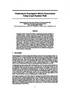
recommended if convergence to the stationary point is of the most importance. However, although it has the same time complexity as lraNMF MU, the modified version is slightly slower. Based on the above convergence analysis, we found an interesting property of the proposed update rules that they can be applied to the data with mixed signs directly. For most of the existing NMF algorithms, however, we have to project the observation matrix to nonnegative space at first. As an ˜B ˜ T , where the elements of A ˜ ∈ R50×10 and B ˜ ∈ R1000×10 were example shown in Fig.1, let Y = A
drawn from independent standard normal distributions. Consequently almost 50% of the elements of Y were negative. Then lraNMF MU was compared with NMF MU where the former used the original data Y directly whereas NMF MU used the projected version Y+ as usual. From the figure, lraNMF MU
not only converged faster, but also achieved better fit 2 .
950 lraNMF_MU NMF_MU
Fitting error: kY − ABT k F
900 850 800 750 700 650 600 550 0 10
1
2
10
10
3
10
Iteration number
Fig. 1: Convergence of lraNMF MU in the factorization of a data matrix with almost 50% negative elements. Note that lraNMF MU fits the model better and its computational complexity of each iteration is also much lower than the standard NMF MU.
2) Convergence of lraNMF HALS: The convergence analysis for lraNMF HALS is much easier as in (3) the elements of Yi has already had mixed signs. From the convergence of HALS the convergence of lraNMF HALS yields immediately. In fact, each time HALS solves the following model min fi = ∥Yi − ai bTi ∥2F
ai ,bi
(14) s.t. ai ∈
×1 RM , +
bi ∈
N ×1 R+ ,
˜B ˜ T − ABT ∥2F . From To solve (1), NMF MU actually solves ∥Y+ − ABT ∥2F instead whereas lraNMF MU solves ∥A ˜B ˜ T approximates Y better than Y+ does, lraNMF MU can achieve better fit than NMF MU. Proposition 1(ii), once A 2
February 17, 2012
DRAFT
IEEE TRANSACTIONS ON SIGNAL PROCESSING, T-SP-12595-2011.R2
where Yi = Y −
∑
T j̸=i aj bj .
9
First bi ̸= 0 is fixed and optimal ai is obtained by solving min fi (ai ) =bTi bi aTi ai − 2bTi YiT ai + c ai
(15) s.t. ai ∈
×1 RM , +
where c is a constant irrelevant to ai . Consider the Lagrangian function of (15) L(ai , λ) = fi (ai ) −
M ∑
λk aki ,
(16)
k=1
where λ = [λ1 , λ2 , · · · , λM
]T
consists of the Lagrangian multipliers. By setting ai =
1 bTi bi
(Yi bi + λ).
∂L ∂aki
= 0, we have
(17)
From the Karush-Kuhn-Tucker necessary conditions, we have aki ≥ 0 and λk ≥ 0, and aki λk = 0. Let xi = Yi bi . Obviously, if xki ≥ 0, let λk = 0 and thus aki = xki ≥ 0. Otherwise, if xki < 0, let λk = −xki > 0 and aki = 0 holds. In summary, ai =
1 bTi bi
[Yi bi ]+
(18)
is the unique global minimum of (15). Similar analysis can be performed with respect to bi . In other words, each time HALS and lraNMF HALS solve a quadratic programming model with nonnegative constraints and give the unique global optimal solution in closed form, therefore HALS and lraNMF HALS always converge to a stationary point [20]. This may explain why HALS converges faster than NMF MU in practice and gives more stable results. Some discussion about this topic can also be found in [1], [17]. D. Applications to Extended NMF There have been a large number of variants of standard NMF which were proposed for different purposes. For example, sparse NMF [21], manifold regularized discriminative NMF [9], Graph Regularized NMF [8], semiNMF [11], just to name a few. They are generally realized by imposing additional constraints on A and/or B, i.e., by employing different penalty functions JA , JB in (1). It is obvious that all these methods benefit from the proposed methods as long as they are based on Euclidean distance. ˜B ˜ T be a low rank approximation, the only thing we need to do is replacing the Generally, let Y ≈ A ˜ A ˜ T A)]+ and [A( ˜ B ˜ T B)]+ , respectively. For example, extension to multiplications YT A and YB by [B(
semiNMF is straightforward (see [11] for the original update rules): ˜ B ˜ T B)(BT B)−1 , A ← A( √ ˜ A ˜ T A)]+ + B[AT A]− [B( , B←B~ ˜ A ˜ T A)]− + B[AT A]+ [B( February 17, 2012
(19)
DRAFT
IEEE TRANSACTIONS ON SIGNAL PROCESSING, T-SP-12595-2011.R2
10
where X− = X+ − X, B is nonnegative and A has mixed signs. The time complexity of (19) is also O(pN R2 ) for each iteration, i.e., typically about M/R times faster than the original update rules.
Now sparse NMF is considered since it has a close relation to the learning parts ability of NMF. We develop our sparse lraNMF basing on the following sparseness measure [21] √∑ ∑ √ n− xi / x2i √ , ∀x ∈ Rn×1 . S(x) = n−1
(20)
Note that it is generally unrealistic to require both A and B to be sparse without increasing the fitting error. Particularly, a less sparse factor A often leads to sparser factor B, and vice versa [22]. For simplicity and robustness reasons, in this paper we improve the sparsity of B by reducing the sparsity of A. In ∑ details, we restrict the columns of A to have unit L1 norm and define JA = i,j a2ij . Then A is updated [
by using A←A~
] ˜ B ˜ T B) A(
+
A(BT B) + αA A
.
(21)
The matrix B is still updated by using (5) or (6). To make the columns of A have unit L1 norm, after each iteration A, B are normalized as A ← AD−1 and B = BD, where D ∈ RR×R is a diagonal ∑ matrix whose diagonal entries are i air . This normalization will not affect the total fitting error and the sparseness of A (its influence on J(A) is also almost negligible because J(A) is generally quite small under the unit L1 norm constraints). From (20) and (21), a larger value of αA leads to a smaller value of JA , i.e., a less sparse factor A, and consequently a sparser factor B. By tuning the value of αA , αB and exchanging the roles of A and B sparse B or A yields. Note also that the update formula
(21) without low-rank approximation has ever been proposed to improve the smoothness of A, see, e.g., [6] and references therein. From this point of view, (21) is actually able to improve the sparseness of B and the smoothness of A. Note also that, by lraNMF, the observation data matrix is approximated by two nonnegative low rank matrices A and B. If we want to impose some additional constraints on the factors, say B, we can also simply run any existing constrained NMF (coNMF) algorithm on the low rank matrix B directly. In details, a constrained NMF can be realized by the following two steps: 1) performing unconstrained NMF by using efficient lraNMF: Y ≈ ABT , where A and B are nonnegative and have low rank R. ´ B) ´ = coNMF(BT ) and 2) running coNMF, for example, on the reduced nonnegative matrix B: (A, ´ B ´ T yields with desired nonnegative factor B ´ due to the coNMF. thus Y ≈ (AA)
The first step is very efficient from the aforementioned analysis. In the second step the new observation February 17, 2012
DRAFT
IEEE TRANSACTIONS ON SIGNAL PROCESSING, T-SP-12595-2011.R2
11
matrix B is much smaller than the original data matrix Y and thus coNMF can be more efficient. Therefore, most existing constrained NMF algorithms may benefit from the above procedure. III. S EQUENTIAL N ONNEGATIVE T UCKER D ECOMPOSITION WITH LRA NMF In many applications the data are often represented by multi-way arrays with different modes such as subjects, groups, trials, and classes, together with the intrinsic dimensions of space, time, and frequency. In these cases tensors are more natural representation of data and consequently tensor decompositions are recently emerging as promising tools for exploratory analysis of multidimensional data in diverse applications, especially, in multiway blind source separation (BSS), feature extraction, classification, prediction, and multiway clustering [1], [23]–[25]. By virtue of their multiway nature, tensors provide powerful tools for analysis and fusion of large scale, multi-modal, massive data together with a mathematical backbone for the discovery of underlying hidden complex data structures [1], [23], [26]. Before proceeding the derivations, some basic notations for tensors are introduced as follows. Basic notations. Tensors are denoted by underlined capital boldface letter, e.g., Y ∈ RI1 ×I2 ×···×IN . The order of a tensor is the number of modes, also known as ways or dimensions (e.g., space, time, frequency, subjects, trials, classes, groups, conditions). Standard notations and basic tensor operations proposed in [25] are used. In details, the mode-n product Y = G ×n A of a tensor G ∈ RR1 ×R2 ×···×RN and a matrix A ∈ RI×Rn is a tensor Y ∈ RR1 ×···×Rn−1 ×I×Rn+1 ×···×RN , with elements yr1 ,r2 ,...,rn−1 ,in ,rn+1 ,...,rN = ∑R n I1 ×I2 ×···×IN in modern =1 (gr1 ,r2 ,...,RN )(ain ,rn ). Unfolding (matricization, flattening) of a tensor Y ∈ R n is denoted as Y(n) ∈ RIn ×Πk̸=n Ik , which consists of arranging all possible mode-n tubes as the columns
of a matrix [25]. Given a tensor Y ∈ RI1 ×I2 ···×IN , there are two basic models for tensor decompositions, i.e., the Canonical Polyadic decomposition (or CANDECOMP/PARAFAC, CP) [27], [28] and the Tucker decomposition [29]. Consider the Tucker decompositions of a given data tensor Y: Y = G ×1 A(1) ×2 A(2) · · · ×N A(N ) ,
(22)
where G ∈ RR1 ×R2 ···×RN is the core tensor, A(n) ∈ RIn ×Rn (n = 1, 2, · · · , N ) are the component matrices. It can be easily verified that the matrix factorization Y = ABT is simply a special case of Tucker decompositions: Y = B ×1 A
(23)
where B ∈ RN ×R is severed as the core tensor and A ∈ RM ×R denotes the component matrix.
February 17, 2012
DRAFT
IEEE TRANSACTIONS ON SIGNAL PROCESSING, T-SP-12595-2011.R2
12
If G in (22) is required to be superdiagonal, i.e., R1 = R2 · · · = RN = R, and G has nonzero entries only on its super-diagonal, the CP decomposition yields. In this paper we do not impose any special structural constraints on the core tensor G. Instead, we impose nonnegativity on A(n) and G, which is generally referred to as nonnegative Tucker decomposition (NTD) [1], [30], [31]. Parallel to NMF, NTD is purely based on additions and tries to give parts based representation of nonnegative tensors using multilinear algebra. NTD has been found a wide range of applications in such as feature extraction, pattern recognition and classification and hence has attracted increasing interests in recent years, e.g., see [1], [30], [31] and references therein. NTD can be achieved by solving the following model: min ∥Y − G ×1 A(1) ×2 · · · ×N A(N ) ∥2F , R1 ×R2 ×···×RN s.t. G ∈ R+ ,
(24)
In ×Rn A(n) ∈ R+ , n = 1, 2, · · · , N,
∑ ∑ 1 where ∥Y∥F = ( Ii11=1 · · · IiNN=1 yi21 ···iN ) 2 . By far many algorithms are proposed to solve optimization problem (24) based on nonnegative alternating least square (NALS) iterations. That is, each time the objective function is optimized with respect to only one loading matrix A(n) or one column of it. As a result, we have to unfold the observation tensor from one mode to another in each iteration. Such unfolding consumes a lot of time and is the major bottleneck to achieve high efficiency of nonnegative Tucker decomposition methods. Note that by using aforementioned mode-n unfolding operator, (24) can be rewritten as min ∥Y(n) − A(n) B(n)T ∥2F s.t. A
(n)
∈
RI+n ×Rn , B(n)
∈
˘ RI+n ×Rn ,
where I˘n = Πk̸=n Ik , n = 1, 2, · · · , N , and ( ) B(n) = A(N ) · · · ⊗ A(n+1) ⊗ A(n−1) ⊗ · · · A(1) GT(n) .
(25)
(26)
We have total N different unfolding versions. This suggests that NTD can be viewed as a series of NMF problems. Note that Y(n) ∈ RIn ×In is usually very large. Therefore, even if run NMF on only one mode ˘
matricization the runtime is still considerable. Fortunately, very often there holds that I˘n ≫ In ≫ Rn . This makes it possible to dramatically speed up NTD by using the idea of lraNMF in each mode. Here, we suggest two ways to perform sequential nonnegative Tucker based on lraNMF (named lraSNTD hereafter):
February 17, 2012
DRAFT
IEEE TRANSACTIONS ON SIGNAL PROCESSING, T-SP-12595-2011.R2
13
1) Extraction of Nonnegative Factors Based on Unconstrained Tucker Decomposition: In this case one can simply start from truncated HOSVD [23], [24] and then extract nonnegative factors based on ˜ ×1 A ˜ (1) · · · ×N A ˜ (N ) , A ˜ (n) ∈ RIn ×Ln be an unconstrained Tucker the decomposed results. Let Y ≈ G
decomposition. From (25), nonnegative A(n) can be estimated from NMF of Y(n) . If we run ordinary ˜ (n) NMF on Y(n) , the complexity per iteration is O(Πi Ii Rn ), which is quite considerable. Note that A ˜ (n) (computed from (26)) just form the low-rank approximation of Y(n) , from (25). Therefore, we and B
can run lraNMF-like iterations to extract the nonnegative factors A(n) using multiplicative updates: [ ] ˜ (n) (B ˜ (n)T B(n) ) A + A(n) ← A(n) ~ , A(n) (B(n)T B(n) ) (27) ] [ ˜ (n) (A ˜ (n)T A(n) ) B + B(n) ← B(n) ~ . (n) (n)T (n) B (A A ) By using above update rules the computational speed is about min(In , I˘n )/Rn times faster for each mode than those without low-rank approximation procedure 3 . Note that we do not need to load the original date tensor Y into memory but instead only its low-rank factors. Similarly, we can derive the HALS version of sequential NTD and is omitted here for simplicity. ˜ can be updated as Finally the core tensor G ( ) ( ) ˜ ←G ˜ ×1 A(1)† A ˜ (1) · · · ×N A(N )† A ˜ (N ) , G
where
†
(28)
denotes the pseudo-inverse of matrices, thereby leading to some negative entries in G, which
makes the decomposition a kind of semi- Nonnegative Tucker decomposition. To perform full nonnegative Tucker decomposition, the following optimization problem should be solved: ˜ ×1 A(1) · · · ×N A(N ) − G ×1 A(1) · · · ×N A(N ) ∥F , min ∥G G
(29)
where G is restricted to be nonnegative. Analogous to NMF, the nonnegative core tensor can be updated iteratively by using G←G~
[ ] ˜ ×1 U(1) · · · ×N U(N ) G G ×1
U(1) · · ·
×N
U(N )
+
,
(30)
where U(n) = A(n)T A(n) .
(31)
Note that during the iterations the numerator and U(n) in (30) remain unchanged and only need to be computed once. Thus G can be computed quite efficiently. 3
Assuming that Ln = Rn , n = 1, 2, · · · , N, for simplicity.
February 17, 2012
DRAFT
IEEE TRANSACTIONS ON SIGNAL PROCESSING, T-SP-12595-2011.R2
14
13000
Fitting error: kY − ABT k F
Fitting error: kY ∗ − ABT k F
12800
6591
3394
1748
900
lraNMF_MU NMF_MU lraNMF_HALS HALS 0
10
1
10
2
10 Iteration number
lraNMF_MU NMF_MU lraNMF_HALS HALS
10803
8978
7461
6200 0 10
3
10
(a) SNR=20dB
1
10
2
10 Iteration number
3
10
(b) SNR=20dB
lraNMF_MU NMF_MU lraNMF_HALS HALS
13497
7990
4730
lraNMF_MU NMF_MU lraNMF_HALS HALS
4.35
10
Fitting error: kY − ABT k F
Fitting error: kY ∗ − ABT k F
22800
4.34
10
4.33
10
4.32
10
4.31
10
4.3
10
2800 0 10
1
10
2
10 Iteration number
(c) SNR=10dB
3
10
0
10
1
10
2
10 Iteration number
3
10
(d) SNR=10dB
Fig. 2: Evolution of fit to noisy observations and true latent matrices versus the iteration number with 20dB, 10dB of additive Gaussian noise, respectively. Y = Y∗ + E denotes the noisy observation matrix and was factorized by each NMF algorithm. Y∗ is the latent noiseless matrix, E is the Gaussian noise. Note that computational cost of each iteration of lraNMF is much lower than the standard NMF algorithms.
In this case Tucker decomposition is served as a dimensionality and noise reduction tool in high order space. Any robust and efficient unconstrained Tucker decomposition algorithm can be used in the first step. 2) Direct Extraction of Nonnegative Factors: In the most cases we do not need to run extra Tucker decomposition in advance. To obtain nonnegative factors, we follow the steps: •
extract nonnegative A(n) by directly running lraNMF on the unfolding matrix Y(n) of Y;
•
update Y ← Y ×n A(n)† ; Repeat the above procedure for n = 1, 2, · · · , N till all the nonnegative component matrices are
February 17, 2012
DRAFT
IEEE TRANSACTIONS ON SIGNAL PROCESSING, T-SP-12595-2011.R2
15
estimated. Note that ordinary NMF algorithms can not provide satisfying results in sequential nonnegative Tucker decomposition because Y generally contain many negative elements due to the matrix inverse operation. This obstacle does not exist in lraNMF. Note also that in this procedure the observation tensor Y becomes ˜ = Y yields as gradually smaller and the convergence consequently becomes gradually faster. Finally, G ˜ ×1 A(1) · · · ×N A(N ) , where the mode matrices are nonnegative and G ˜ is with mixed signs. Y ≈G
Following update rule (30)-(31) again the nonnegative core tensor can be obtained, if it is necessary. Generally, the second approach, i.e., direct extraction method, is more efficient since it does not depend on an extra Tucker decomposition. IV. L OW R ANK A PPROXIMATION AND ACCELERATION FOR L ARGE - SCALE P ROBLEMS In this section we briefly review low-rank approximation techniques of a given matrix Y. The optimal low-rank approximation can be obtained by PCA or tSVD (in the least square sense). The L largest singular values and the associated singular vectors form the optimal rank-L approximation. For largescale problems SVD suffers from heavy computation cost and memory consumption. Typically, the Krylov subspace method computes the tSVD in O(M N L) time [32]. Another category of low-rank approximations is based on randomization, see e.g., [3], [32]–[34]. The readers are suggested to refer to [32], [34] for comprehensive developments on this topic. All these low-rank approximation methods can be incorporated into the proposed scheme. Which one is the most suitable depends on the specific tasks at hand, because different methods are based on different assumptions and generally lead to different tradeoff between accuracy, efficiency, and some bias [32], [34]. A quite simple and efficient random low-rank approximation method proposed in [3] is also employed as an alternative to tSVD in this paper, see Algorithm 1. Algorithm 1 also requires O(M N L) flops 4
, due to the matrix multiplications in step 2 and 4. However, this algorithm only needs to access the
large matrix Y twice. With tools such as blocking of operations, high-level linear algebra subroutines, Algorithm 1 can be tailored for very large scale problems and is able to achieve satisfying performance. A method which was proposed in [1], [35] can also be incorporated in lraNMF to further reduce the time complexity and is described as follows. From Y ≈ ABT , since the underlying structure can be relatively simple and low rank, or equivalently, the information in Y should be highly redundant, we may 4
However, if Ω is well structured, an implementation of Algorithm 1 in O(M N log L) time can be achieved, see [32] for
details.
February 17, 2012
DRAFT
IEEE TRANSACTIONS ON SIGNAL PROCESSING, T-SP-12595-2011.R2
16
Algorithm 1 Randomized low-rank approximation algorithm Require: M × N matrix Y and integer L, L ≪ M . 1:
Drawn an N × L Gaussian random matrix Ω.
2:
X = YΩ.
3:
˜ ∈ RM ×L whose columns form an orthogonal basis for the range of X. Construct A
4:
˜ and B ˜ , where B ˜ =A ˜ T Y. return A
use only partial columns of Y to approximate the columns of A. Similarly, we can use only partial rows of Y to approximate the columns of B. For simplicity, let Im ⊆ {1, 2, · · · , M } and In ⊆ {1, 2, · · · , N }. Now we assume that only the columns of Y specified by In will be used to estimate A and the rows ˜B ˜ TI and YIm ≈ A ˜ Im B ˜ T , the update rules specified by Im will be used to estimate B. From YIn ≈ A n
(5) become
[ B←B~
A←A~
˜ A ˜ T AIm ) B( Im
] +
B(ATIm AIm ) [ ] ˜ B ˜ T BIn ) A( In
+
A(BTIn BIn )
,
(32) .
By thus, the computation complexity is further reduced. For the tensor case, any fast Tucker decomposition, such as HOSVD and HOOI, can be served as the low-rank approximation. Generalized from tensor CUR decomposition, two efficient tensor decomposition methods are proposed in [36] based on fiber sampling. Sequential extraction based on tSVD is also proposed in [37], which achieves a tradeoff between approximation accuracy and efficiency. All these methods can be served as dimensionality reduction for tensors. In extraction and update based NTD, however, low-rank approximation for matrices will be utilized directly without need to perform preliminary Tucker decompositions. V. S IMULATIONS All the simulations were performed on a computer with a 3.3GHz Intel Core i7 CPU and 24Gbytes memory running 64bit MATLAB2008a in Windows 7. Without special specification low-rank approximation was performed by using tSVD, and L = R. 5000×50 Simulation 1: Convergence analysis. We generated matrices A ∈ R+ and B ∈ R5000×50 . Then +
we constructed Y∗ = ABT and Y = Y∗ + E, where E denoted the independent Gaussian noise
February 17, 2012
DRAFT
IEEE TRANSACTIONS ON SIGNAL PROCESSING, T-SP-12595-2011.R2
f*/f*max
Relative performance
t/tmax 13s
22s
17
71s
219s
138s
74s
1
f/fmax 310s
0.8 0.6 0.4 0.2 M F_ M U
LS A H
N
S
F_ PG N M
F_ A N M
N
M F_ BP
A LS M F_ H
lra N
lra N M
F_ M U
0
Fig. 3: Comparison of performance in terms of runtime and final fit of each NMF algorithm with 10dB additive Gaussian noise. Here Y ∈ R5000×5000 , R=50, f ∗ = ∥Y∗ − ABT ∥F , f = ∥Y − ABT ∥F , and t denotes the runtime.
35
SIR (dB)
30 25 lraNMF_MU 20
lraNMF_HALS NMF_MU
15
HALS DNNMF
10
NMF_BP 5 −5
0
5 10 15 Noise level (SNR in dB)
20
25
Fig. 4: Mean SIR values of each NMF algorithm and the standard derivations over 100 Monte Carlo runs versus the level of noises in the application of BSS when additive Gaussian noises were involved.
(containing about 50% negative entries). In the noiseless case lraNMF is simply equivalent to ordinary NMF except that it is much faster. We mainly compared their performances in presence of large Gaussian noise measured by signal-to-noise ratio (SNR in dB). Note that the observations contained some negative entries due to the very heavy noise. For ordinary NMF algorithms the negative entries of the observation matrix were truncated at zero to ensure the nonnegativity whereas to lraNMF this truncation was avoided since lraNMF can manipulate the negative elements directly. From Fig.2, lraNMF algorithms reached almost the same minimum as ordinary NMF if noises were
February 17, 2012
DRAFT
IEEE TRANSACTIONS ON SIGNAL PROCESSING, T-SP-12595-2011.R2
18
mild. However, if the noises were heavy, say SNR=10dB, the recovered matrix ABT obtained by lraNMF algorithms matched the true one much better, (see Fig.2(a) and (c)), which suggests that the low rank approximation is also helpful to filter out noises. One may question why the convergence curves in Fig.2(c) is not monotonically decreasing. This is mainly because that the noise level was too high and thus some noises were included in the factors. From Fig.2(d), all the algorithms actually converged very well. This may suggest that, for heavy noisy data, pure pursuit of the minimum fitting error is not sufficient. In this situation some additional constraints on the factors may play important role to retrieve true latent factors. Figure 3 shows the relative performance in terms of time consumption and final fit of each algorithm. In the figure, f ∗ = ∥Y∗ − ABT ∥F , f = ∥Y − ABT ∥F , and t is the runtime. Three additional algorithms were also compared: the projected gradient NMF algorithm (NMF PG) [38], where its maximum iteration number was set to 50, NMF based on block principal pivoting (NMF BP) [12], and NMF based on active set method (NMF AS) [13]. The min- and max- iteration number of NMF BP and NMF AS were set as 50 and 200, respectively. All the other algorithms used 1000 as the maximum iteration number. From Fig.3, lraNMF algorithms approximated the true latent data much better than the others did although they achieved almost the same fit to the noisy data, which shows that lraNMF algorithms are more robust with respect to noise. Moreover, they are much faster than NMF MU and HALS. (They are not exactly M/R = 100 times faster because low-rank approximation procedure also consumed some time, and extra
multiplication of small matrices in each iteration as well). From the experimental results, we conclude that lraNMF algorithms are very efficient for the case where R ≪ M and are more robust to noise. Although in this paper all the noises were assumed to be Gaussian, the case where noises follow distributions other than Gaussian may also be incorporated into lraNMF, as long as a satisfying lowrank approximation can be obtained, from Proposition 1(ii). However, in such a case tSVD may not give the optimal low-rank approximation any longer. We should employ some other suitable low-rank approximation methods. For example, if the noises are very sparse, robust PCA proposed in [39] may be recommended. How to obtain optimal low-rank approximation efficiently for arbitrary noises is beyond the scope of this paper. Here we just emphasize that, low-rank approximation is critical to lraNMF and we should choose it very carefully in practice. Simulation 2 Nonnegative source separation from noisy data. The data was constructed as follows. The columns of B consisted of 10 nonnegative sparse signals chosen from the benchmark of NMFLAB [40] named ACposvsparse.mat. The number of samples was 1000. The elements of the mixing matrix A ∈ R500×10 were drawn from a uniform distribution. Then let Y = ABT and finally different levels February 17, 2012
DRAFT
IEEE TRANSACTIONS ON SIGNAL PROCESSING, T-SP-12595-2011.R2
19
of Gaussian white noise were added to investigate the robustness of the proposed methods to noise. The
(a)
Examples
of
(b) NMFSC:
(c) lraNMF MU:
face images in ORL
S(B)=0.5905;
S(B)=0.6524;
database
Time: 132.8s
Time: 3.5s
Fig. 5: Comparison of NMFSC and lraNMF MU in the analysis of human face images (ORL data). Both NMFSC and lraNMF with sparseness constraint gave parts based representations. However, lraNMF was much faster than NMFSC.
signal-to-interface ratio (SIR) is defined as follows to evaluate the separation accuracy: ∑ 2 s SIR(s, b s) = 10 log10 ∑ t t 2 , bt ) t (st − s
(33)
where s, sb are normalized random variables with zero mean and unit variance, and sb is an estimate of s. The proposed methods were compared with standard NMF MU, HALS, NMF BP, DNNMF [41]. The averaged SIR values of each algorithm with their standard derivations over 100 Monte Carlo trials versus the level of noise were plotted in Fig.4. From the figure, it is obviously that the proposed methods and NMF BP are more robust to Gaussian noise. The largest standard derivation was only 2.2578. When SNR of noise was 0dB, the averaged SIRs of these three algorithms were still larger than 20dB, whereas the other algorithms achieved SIRs less than 15dB. Moreover, the proposed methods are more efficient than the other algorithms. On average, two lraNMF algorithms consumed only 0.5s (seconds) whereas NMF BP consumed 0.9s while the other three algorithms needed more than 2.5s to converge. Simulation 3 In this example the NMF algorithms were evaluated in the application of parts-based representation of images. The observation matrix was constructed by 400 gray image faces chosen from the ORL database [42]. Each image is with the size of 46 × 56 and was vectorized to constitute the rows of Y. Finally a 400 × 2576 nonnegative matrix was constructed and totally R = 25 nonnegative components were to be extracted. For this data set most unconstrained NMF algorithms failed to give parts based representation, such as NMF MU, DNNMF. Additional sparseness constraints was therefore
February 17, 2012
DRAFT
IEEE TRANSACTIONS ON SIGNAL PROCESSING, T-SP-12595-2011.R2
5
20
1.25 Fitness: f/fmin
L=11~20
4.5
1.2
L=21~30
Relative performance
Fitting error: kY − ABT k F
L=1~10
L=31~40
4
L=41~50 3.5 tanα=0.9574 f0
3
α 2.5 1.5
2
Time: t/tmin
1.15 1.1 1.05 1
2.5 3 3.5 4 Low−rank approximation error
4.5
5
(a)
50
100
150
200 250 300 Number of samples
350
400
(b)
Fig. 6: Performance of lraNMF MU based on randomization. (a) illustration of how low-rank approximation error affected the final fit of lraNMF. Here Algorithm 1 was used for low-rank approximation and f0 indicated the results obtained by NMF MU. (b) performance of lraNMF MU as a function of number of sampled rows/columns by using (32).
required to improve the sparseness of results. Here lraNMF MU was simply compared with NMFSC [21]. The maximum iteration number was 2000. For lraNMF MU, αA = 100 was used to impose the sparseness constraints. The results were shown in Fig.5, from which we can observe that both NMFSC and lraNMF MU were able to give sparse representation, but lraNMF was much faster than NMFSC. Figure 6(a) shows how different low-rank approximation errors affected the resulting fit with L = 1, 2, · · · , 50. In this figure, Algorithm 1 was used for low-rank approximation. We ran lraNMF MU 10 times for each L and in each run lraNMF MU started from the same initial values of A and B. From Fig.6(a), when L > R, lraNMF MU achieved almost the same fit as NMF MU without low-rank approximation (indicated by f0 ). If L < R, the fit of lraNMF MU increased approximately linearly with the low-rank approximation error. Larger L often leads to a smaller approximation error, but consumes more time. This is consistent with Proposition 1(ii). Figure 6(b) shows the normalized fit and standard deviations and runtime of lraNMF MU with sampled columns/rows over 100 Monte Carlo runs, by using the update rules (32). From the figure, it can be seen that, when more samples were used, the algorithm was more stable but consumed more time. However, the runtime increased nearly linearly whereas the gain of fit tended to be mild. In practice we can make a tradeoff between the runtime and fit to the data by using sampling techniques for very large-scale problems. Simulation 4: The data set RVC1 was used to investigate the performance of the proposed methods
February 17, 2012
DRAFT
IEEE TRANSACTIONS ON SIGNAL PROCESSING, T-SP-12595-2011.R2
21
Fig. 7: Illustration of how lraSNTD provides parts based representation of a tensor data formed by using 7200 color images included in COIL-100 database. The target tensor has the size of 128×128×3×7200.
in large scale data analysis. RCV1 is an archive of 804,414 newswire stories from Reuters Ltd [43]. The news documents were manually categorized with respect to industries, topics, and regions. For simplicity here we used the cleaned and reorganized data used in [44], where the data that are multilabeled were not considered and categories that contain less than 500 documents were removed. By thus 193,844 documents in 103 categories formed the matrix Y with the size of 193, 844 × 47, 236. See [43], [44] for detailed description of the data. For this data, NNMF in MATLAB2008a, DNNMF, NMF BP and NMF AS ran out of memory on our computer. The NMF method based on random projection (RPNMF) was compared as it was also proposed for large scale problems [14]. In RPNMF, km = kn = 200, the maximum iteration number was 1000. For lraNMF, if tSVD was used, L = R was set; otherwise L = 4R for randomized algorithm. The maximum iteration numbers of lraNMF HALS and lraNMF MU were 1000 and 500, respectively. For all algorithms R = 50 was set. After factorization, the factor A was used as features to cluster the documents by using the K-means algorithm based on correlations. The results were listed in Table II. From the table, clustering accuracy5 achieved by lraNMF was slightly higher than the results reported in [44] and significantly higher than that of RPNMF. Moreover, lraNMF algorithms were more efficient. Among them, lraNMF HALS based on tSVD was the fastest one. From the table, lraNMF based on tSVD performed better than those based on the randomized algorithm. Generally, for the same L, Algorithm 1 is much faster than tSVD. For example, if L = R, Algorithm 1 consumed 5
See Eq.(26) in [44] for the definition.
February 17, 2012
DRAFT
IEEE TRANSACTIONS ON SIGNAL PROCESSING, T-SP-12595-2011.R2
22
TABLE II: Performance comparison in large scale data RCV1 document clustering Algorithm
Time(s)
Fitting error
Accuracy(%)
lraNMF HALS [tSVD]
191.8
398.5213
18.3044
lraNMF HALS [Algorithm 1]
292.6
405.9204
18.7477
lraNMF MU [tSVD]
355.1
398.5375
18.4891
lraNMF MU [Algorithm 1]
556.6
405.1290
16.3085
RPNMF
4642.0
465.4727
3.9181
2.5s and the approximation error was 424, whereas tSVD consumed 46s and the resulting approximation error was 395. Generally, randomized algorithms consumes more time but provides better fit for a larger L. Thus randomized algorithms endows lraNMF with some flexibility for large scale data. Moreover,
randomized algorithms are more suitable for the cases where tSVD can not be computed efficiently or the data matrix Y is too large to fit into memory. Simulation 5: In this simulation NTD was investigated in the application of sparse representation of tensor objects. The observation tensor was constructed by 7200 color images included in the Columbia Object Image Library (COIL-100) [45]. COIL-100 is a database of color images of 100 objects and each object has 72 images. Each image corresponds to one pose of an object and can be naturally represented as a 128 × 128 × 3 tensor. These images formed a big tensor with the size of 128 × 128 × 3 × 7200. To achieve a feature extraction and data compression, R1 = R2 = 16, R3 = 3, R4 = 64 was set for all the algorithms. Fig.7 shows the decomposition results obtained by lraSNTD MU. From the figure, the nonnegative core tensor G and the component matrices A(n) , n = 1, 2, 3, 4, were all very sparse. Note that in NMF, the observation tensor should be matricized first and then decomposed as the product of an encoding matrix and an basis matrix. In NTD, however, the basis is a tensor instead of a matrix, which has a special algebraic structure and can be further decomposed as G ×1 A(1) ×2 A(2) ×3 A(3) with nonnegative constraints, thereby leading to more insightful and sparser representation, see Fig.7. This kind of sparse representation can be widely applied to pattern recognition and classification. As an illustration, Fig.8 shows how lraSNTD was able to give correct class information in the task of classifying four objects selected from COIL-100 database. Note that we only illustrated this kind of ability of NTD rather than provide detailed procedure due to space limitation. In this paper NMF/NTD was mainly considered as flexible tools for nonnegative data analysis and feature extraction rather than a practical implementation of a classifier. The proposed algorithms were also compared with the HONMF [30]
February 17, 2012
DRAFT
IEEE TRANSACTIONS ON SIGNAL PROCESSING, T-SP-12595-2011.R2
(4)
a1
(4)
(4)
a2
(4)
a3
a4
A(4)
1
23
0.5
0 50
100
150 Samples
200
250
Fig. 8: Illustration of how lraSNTD provides correct class information in the task of classifying 4 objects from COIL-100 database. Extension to more classes is straightforward.
TABLE III: Comparison between lraSNTD and HONMF, HALS-NTD in nonnegative Tucker decomposition
S(A1 )
S(A2 )
S(A3 )
S(A4 )
S(G)
Fit
Time (s)
lraSNTD MU
0.6810
0.6339
0.6131
0.5598
0.7700
0.7401
220
HONMF
0.3490
0.3119
0.4574
0.4483
0.7807
0.6290
34022
lraSNTD HALS
0.6962
0.7181
0.6340
0.4930
0.6766
0.7284
174
HALS-NTD
0.7036
0.6312
0.6317
0.4938
0.6845
0.7110
33738
method and HALS-NTD [31] algorithm, see TABLE III for the detailed results, where the fit is defined as b =1− fit(Y, Y)
b F ∥Y − Y∥ , ∥Y∥F
(34)
b is a reconstructed version of Y. Obviously, fit(Y, Y) b = 1 if and only if Y b = Y. In HALS-NTD Y and HONMF the maximum iteration number was 100 while in lraNMF it was 1000. From the table, although all the methods were able to give sparse representation of objects, lraSNTD methods were more than 100 times faster than HONMF and HALS-NTD for this large-scale problem, and achieved better fit. HONMF and HALS-NTD can achieve comparable fit and sparseness of results. But they require more computation time and memory for large tensors. In summary, compared with state of the art NTD algorithms HONMF and HALS-NTD, the proposed lraSNTD methods were much more efficient for very large-scale problems. VI. C ONCLUSION Low-rank approximation has been widely used in various matrix factorization techniques in order to reduce the computational complexity, memory consumption and to suppress noise. However, it can not be February 17, 2012
DRAFT
IEEE TRANSACTIONS ON SIGNAL PROCESSING, T-SP-12595-2011.R2
24
directly incorporated into nonnegative data analysis as it results in factors with mixed signs. In this paper low-rank approximation was introduced to nonnegative matrix factorization methods for the first time, which not only reduces the computational complexity of NMF, but also is helpful to suppress the noise which can be negative. Finally, NMF based on low-rank approximation was generalized to sequential nonnegative Tucker decomposition. Extensive simulations on synthetic data and real data showed that the proposed methods can significantly improve the efficiency of NMF/NTD algorithms, especially for large-scale problems. A PPENDIX A P ROOF OF P ROPOSITION 1 Proof: (i) Define P (X; A, B) = ∥Y − X∥F + ∥X − ABT ∥F , where A ≽ 0, B ≽ 0, X ∈ RM ×N . First of all, ∀ A ≽ 0, B ≽ 0 and X ∈ RM ×N , we have ∥Y − X∥F + ∥X − ABT ∥F ≥ ∥Y − ABT ∥F
(35)
≥ ∥Y − A⋄ B⋄T ∥F = ϵ⋄ .
Moreover, P (A⋄ B⋄T ; A⋄ , B⋄ ) = ϵ⋄ , i.e., P is able to reach the lower bound. This ends the proof. (ii) ϵ⋄ ≤ ∥Y − A∗ B∗ T ∥F is straightforward due to the definition of ϵ⋄ . On the other hand, ∥Y − A∗ B∗ T ∥F ≤ ∥Y − X∥F + ∥X − A∗ B∗ T ∥F = σ + ∥X − A∗ B∗ T ∥F ≤ σ + ∥X − A⋄ B⋄T ∥F ≤ σ + ∥X − Y∥F + ∥Y − A⋄ B⋄T ∥F = 2σ + ϵ⋄ .
That ends the proof of (ii). A PPENDIX B P ROOF OF THE C ONVERGENCE OF LRA NMF MU Proof: Let H = BT and F (h) = 12 ∥yi − Ah∥2F . ∀ht ≻ 0, define 1 e ht + (h − ht )T D(h − ht ) G(h) = F (ht ) + (h − ht )T ▽ 2
and 1 e ht + (h − ht )T AT A(h − ht ), L(h) = F (ht ) + (h − ht )T ▽ 2 February 17, 2012
DRAFT
IEEE TRANSACTIONS ON SIGNAL PROCESSING, T-SP-12595-2011.R2
( where D = diag T
A Aht ht ,
AT Aht ht
25
) is a diagonal matrix whose diagonal elements are specified by the vector
e ht = −[AT yt ]+ + AT Aht is a column of ▽ e TB . Following the proof in [16], the matrix and ▽ t
[D − AT A] is semipositive and thus G(h) ≥ L(h), ∀h. Note that ht+1 = ht ~
[AT yi ]+ . AT Aht
(36)
is the global minimum of G(h), i.e., G(ht+1 ) ≤ G(h), ∀h. As a result, L(ht+1 ) ≤ G(ht+1 ) ≤ G(ht ) ≤ F (ht ). On the other hand, F (h) can be rewritten as 1 F (h) = F (ht ) + (h − ht )T ▽ht + (h − ht )T AT A(h − ht ), 2
where ▽ht = −AT yi + AT Aht . Hence, L(h) − F (h) = (h − ht )T (AT yi − [AT yi ]+ ).
Let u = ht+1 − ht = ht ~
(37)
[AT yi ]+ AT Aht
− ht and v = AT yi − [AT yi ]+ . It can be easily verified that 0 if [AT yi ]k ≥ 0, uk vk = −htk [AT yi ]k ≥ 0 if [AT yi ]k < 0,
(38)
where htk and [AT yi ]k are the k th elements of vector ht and AT yi , respectively. In other words, L(ht+1 ) − F (ht+1 ) ≥ 0, which means that F (ht+1 ) ≤ L(ht+1 ) ≤ F (ht ), under the update rule (36).
Using matrix version of (36) we have H=H~
[AT Y]+ . AT AH
(39)
From B = HT , the update rule for B yields. By reversing the roles of A and B, the update formulas (5) yield. ACKNOWLEDGMENT The authors sincerely thank Prof. Lieven De Lathauwer and the anonymous reviewers for their insightful comments and suggestions that led to the present improved version of the original manuscript. R EFERENCES [1] A. Cichocki, R. Zdunek, A.-H. Phan, and S. Amari, Nonnegative Matrix and Tensor Factorizations: Applications to Exploratory Multi-way Data Analysis and Blind Source Separation.
Chichester: Wiley, 2009.
[2] J. B. Tenenbaum, V. de Silva, and J. C. Langford, “A global geometric framework for nonlinear dimensionality reduction,” Science, vol. 290, no. 5500, pp. 2319–2323, 2000. [3] P.-G. Martinsson, V. Rokhlin, and M. Tygert, “A randomized algorithm for the decomposition of matrices,” Applied and Computational Harmonic Analysis, vol. 30, no. 1, pp. 47 – 68, 2011. February 17, 2012
DRAFT
IEEE TRANSACTIONS ON SIGNAL PROCESSING, T-SP-12595-2011.R2
26
[4] G. Tomasi, Practical and computational aspects in chemometric data analysis: Ph.D. dissertation.
Department of Food
Science, Royal Veterinary and Agricultural University, 2006. [5] D. D. Lee and H. S. Seung, “Learning the parts of objects by non-negative matrix factorization,” Nature, vol. 401, no. 6755, pp. 788–791, Oct 21 1999. [6] M. Berry, M. Browne, A. Langville, V. Pauca, and R. Plemmons, “Algorithms and applications for approximate nonnegative matrix factorization,” Computational Statistics & Data Analysis, vol. 52, no. 1, pp. 155–173, Sep. 2007. [7] P. Paatero and U. Tapper, “Positive matrix factorization: A non-negative factor model with optimal utilization of error estimates of data values,” Environmetrics (London, Ont.), vol. 5, no. 2, pp. 111–126, 1994. [8] D. Cai, X. He, J. Han, and T. Huang, “Graph regularized nonnegative matrix factorization for data representation,” Pattern Analysis and Machine Intelligence, IEEE Transactions on, vol. 33, no. 8, pp. 1548 –1560, aug. 2011. [9] N. Guan, D. Tao, Z. Luo, and B. Yuan, “Manifold regularized discriminative nonnegative matrix factorization with fast gradient descent,” Image Processing, IEEE Transactions on, vol. 20, no. 7, pp. 2030 –2048, july 2011. [10] Y. Chen, L. Wang, and M. Dong, “Non-negative matrix factorization for semisupervised heterogeneous data coclustering,” Knowledge and Data Engineering, IEEE Transactions on, vol. 22, no. 10, pp. 1459 –1474, oct. 2010. [11] C. Ding, T. Li, and M. Jordan, “Convex and semi-nonnegative matrix factorizations,” Pattern Analysis and Machine Intelligence, IEEE Transactions on, vol. 32, no. 1, pp. 45 –55, jan. 2010. [12] J. Kim and H. Park, “Toward faster nonnegative matrix factorization: A new algorithm and comparisons,” in Data Mining, 2008. ICDM ’08. Eighth IEEE International Conference on, dec. 2008, pp. 353–362. [13] H. Kim and H. Park, “Nonnegative matrix factorization based on alternating nonnegativity constrained least squares and active set method,” SIAM Journal on Matrix Analysis and Applications, vol. 30, no. 2, pp. 713–730, 2008. [14] F. Wang and P. Li, “Efficient Nonnegative Matrix Factorization with Random Projections,” in SDM, 2010, pp. 281–292. [15] C. Boutsidis and P. Drineas, “Random Projections for the Nonnegative Least-Squares Problem,” ArXiv e-prints, Dec. 2008. [16] D. D. Lee and H. S. Seung, “Algorithms for non-negative matrix factorization,” in Advances in Neural Information Processing Systems 13, T. K. Leen, T. G. Dietterich, and V. Tresp, Eds. MIT Press: Cambridge, MA, 2000, pp. 556–562. [17] R. Bro, “Multi-way analysis in the food industry: Models, algorithms & applications,” Food technology, p. 309, 1998. [Online]. Available: http://curis.ku.dk/ws/files/13035961/Rasmus Bro.pdf [18] Z. He, A. Cichocki., S. Xie, and K. Choi, “Detecting the number of clusters in n-way probabilistic clustering,” IEEE Transactions on Pattern Analysis and Machine Intelligence, vol. 32, no. 11, pp. 2006–2021, 2010. [19] C.-J. Lin, “On the convergence of multiplicative update algorithms for nonnegative matrix factorization,” Neural Networks, IEEE Transactions on, vol. 18, no. 6, pp. 1589 –1596, nov. 2007. [20] D. G. Luenberger, Linear and Nonlinear Programming, 2nd ed.
Kluwer Academic Pub, 2003.
[21] P. O. Hoyer, “Non-negative matrix factorization with sparseness constraints,” Journal of Machine Learning Research, vol. 5, pp. 1457–1469, Nov 2004. [22] G. Zhou, S. Xie, Z. Yang, J.-M. Yang, and Z. He, “Minimum-volume-constrained nonnegative matrix factorization: Enhanced ability of learning parts,” Neural Networks, IEEE Transactions on, vol. 22, no. 10, pp. 1626 –1637, oct. 2011. [23] L. De Lathauwer, B. De Moor, and J. Vandewalle, “A multilinear singular value decomposition,” SIAM Journal on Matrix Analysis and Applications, vol. 21, pp. 1253–1278, 2000. [24] ——, “On the best rank-1 and rank-(r1,r2,. . .,rn) approximation of higher-order tensors,” SIAM J. on Matrix Analysis and Applications, vol. 21, no. 4, pp. 1324–1342, 2000.
February 17, 2012
DRAFT
IEEE TRANSACTIONS ON SIGNAL PROCESSING, T-SP-12595-2011.R2
27
[25] T. G. Kolda and B. W. Bader, “Tensor decompositions and applications,” SIAM REVIEW, vol. 51, no. 3, pp. 455–500, 2009. [26] A. Cichocki, “Generalized Component Analysis and Blind Source Separation Methods for Analyzing Mulitchannel Brain Signals,” in Statistical and Process Models for Cognitive Neuroscience and Aging. Lawrence Erlbaum Associates, 2007, pp. 201–272. [27] J. Carroll and J.-J. Chang, “Analysis of individual differences in multidimensional scaling via an n-way generalization of Eckart-Young decomposition,” Psychometrika, vol. 35, no. 3, pp. 283–319, September 1970. [28] R. A. Harshman, “Foundations of the PARAFAC procedure: Models and conditions for an ’explanatory’ multi-modal factor analysis,” UCLA Working Papers in Phonetics, vol. 16, no. 1, 1970. [29] L. Tucker, “Some mathematical notes on three-mode factor analysis,” Psychometrika, vol. 31, no. 3, pp. 279–311, September 1966. [30] M. Mørup, L. K. Hansen, and S. M. Arnfred, “Algorithms for sparse nonnegative Tucker decompositions,” Neural computation, vol. 20, no. 8, pp. 2112–2131, August 2008. [31] A. H. Phan and A. Cichocki, “Extended HALS algorithm for nonnegative Tucker decomposition and its applications for multiway analysis and classification,” Neurocomputing, vol. 74, no. 11, pp. 1956 – 1969, 2011. [32] M. W. Mahoney, “Randomized algorithms for matrices and data,” ArXiv e-prints, no. 4, 2011. [33] P. Drineas, R. Kannan, and M. W. Mahoney, “Fast Monte Carlo algorithms for matrices II: Computing a low-rank approximation to a matrix,” SIAM J. Comput., vol. 36, no. 1, pp. 158–183, July 2006. [34] N. Halko, P.-G. Martinsson, and J. A. Tropp, “Finding structure with randomness: Probabilistic algorithms for constructing approximate matrix decompositions,” Dec. 2010. [Online]. Available: http://arxiv.org/abs/0909.4061 [35] A. Cichocki and H. A. Phan, “Fast local algorithms for large scale nonnegative matrix and tensor factorizations,” IEICE Transactions on Fundamentals of Electronics, Communications and Computer Sciences, vol. E92-A, no. 3, pp. 708–721, 2009. [36] C. F. Caiafa and A. Cichocki, “Generalizing the column-row matrix decomposition to multi-way arrays,” Linear Algebra and its Applications, vol. 433, no. 3, pp. 557 – 573, 2010. [37] N. Vannieuwenhoven, R. Vandebril, and K. Meerbergen, “On the truncated multilinear singular value decomposition,” in Numerical Analysis and Applied Mathematics Section.
Department of Computer Science, K.U.Leuven, 2011. [Online].
Available: http://www.cs.kuleuven.be/publicaties/rapporten/tw/TW589.abs.html [38] C.-J. Lin, “Projected gradient methods for nonnegative matrix factorization,” Neural Comput., vol. 19, no. 10, pp. 2756– 2779, October 2007. [39] E. J. Candes, X. Li, Y. Ma, and J. Wright, “Robust Principal Component Analysis?” ArXiv e-prints, Dec. 2009. [40] A. Cichocki and R. Zdunek. (2006) NMFLAB for signal processing. [Online]. Available: http://www.bsp.brain.riken.jp/ ICALAB/nmflab.html [41] R. Zdunek, H. A. Phan, and A. Cichocki, “Damped Newton iterations for nonnegative matrix factorization,” Australian Journal of Intelligent Information Processing Systems, vol. 12, no. 1, pp. 16–22, 2010. [42] “ORL database.” [Online]. Available: http://www.zjucadcg.cn/dengcai/Data/FaceData.html [43] D. D. Lewis, Y. Yang, T. G. Rose, and F. Li, “RCV1: A new benchmark collection for text categorization research,” Journal of machine learning research, vol. 5, pp. 361–397, December 2004. [44] W.-Y. Chen, Y. Song, H. Bai, C.-J. Lin, and E. Y. Chang, “Parallel spectral clustering in distributed systems,” IEEE Transactions on Pattern Analysis and Machine Intelligence, vol. 33, no. 3, pp. 568–586, 2011.
February 17, 2012
DRAFT
IEEE TRANSACTIONS ON SIGNAL PROCESSING, T-SP-12595-2011.R2
28
[45] S. A. Nene, S. K. Nayar, and H. Murase, “Columbia object image library (COIL-100),” 1996. [Online]. Available: http://www.cs.columbia.edu/CAVE/software/softlib/coil-100.php
February 17, 2012
DRAFT