such 3D model obtained from a novel subject inside a spe- cial multi-view rig (dome). In this case, the ârightâ camera configuration was found after some trial and ...
MITSUBISHI ELECTRIC RESEARCH LABORATORIES http://www.merl.com
Finding Optimal Views for 3D Face Shape Modeling Jinho Lee Baback Moghaddam Hanspeter Pfister Raghu Machiraju TR2004-024
April 2004
Abstract A fundamental problem in multi-view 3D face modeling is the determination of the set of optimal views (poses) required for accurate 3D shape estimation of a generic face. There is no analytical solution to this problem, instead (partial) solutions require (near) exhaustive combinatorial search, hence the inherent computational difficulty of this task. We build on our previous modeling framework which uses an efficient contour-based silhouette matching method and extend it by aggressive pruning of the view-sphere with view clustering and imposing various imaging constraints. A multiview optimization search is performed using both model-based (eigenhead) and datadriven (visual hull) methods, yielding comparable best views. These constitute the first reported set of optimal views for 3D face shape capture and should provide useful empirical guidelines for the design of 3D face recognition systems.
Published in: IEEE Int’l Conf. on Automatic Face & Gesutre Recognition (FG’04)
This work may not be copied or reproduced in whole or in part for any commercial purpose. Permission to copy in whole or in part without payment of fee is granted for nonprofit educational and research purposes provided that all such whole or partial copies include the following: a notice that such copying is by permission of Mitsubishi Electric Research Laboratories, Inc.; an acknowledgment of the authors and individual contributions to the work; and all applicable portions of the copyright notice. Copying, reproduction, or republishing for any other purpose shall require a license with payment of fee to Mitsubishi Electric Research Laboratories, Inc. All rights reserved. c Mitsubishi Electric Research Laboratories, Inc., 2004 Copyright 201 Broadway, Cambridge, Massachusetts 02139
Publication History:– 1. First printing, TR2004-024, April 2004
Finding Optimal Views for 3D Face Shape Modeling Jinho Lee †‡ †
Baback Moghaddam †
Mitsubishi Electric Research Laboratories
Hanspeter Pfister † ‡
Raghu Machiraju ‡
The Ohio State University
201 Broadway, Cambridge MA 02139 USA
395 Dreese Lab. 2015 Neil Ave. Columbus OH 43210 USA
{leejh,baback,pfister}@merl.com
{leeji,raghu}@cis.ohio-state.edu
Abstract A fundamental problem in multi-view 3D face modeling is the determination of the set of optimal views (poses) required for accurate 3D shape estimation of a generic face. There is no analytical solution to this problem, instead (partial) solutions require (near) exhaustive combinatorial search, hence the inherent computational difficulty of this task. We build on our previous modeling framework [6, 8] which uses an efficient contour-based silhouette method and extend it by aggressive pruning of the view-sphere with view clustering and various imaging constraints. A multi-view optimization search is performed using both model-based (eigenheads) and data-driven (visual hull) methods, yielding comparable best views. These constitute the first reported set of optimal views for 3D face shape capture and provide useful empirical guidelines for the design of 3D face recognition systems.
1. Introduction Active sensing for 3D face model acquisition still requires costly devices thus many proposed methods recover 3D face shape from 2D images or projections. Some of these are based on a direct approach which obtains 3D location of points on the face through dense 2D correspondence on the images [9, 5, 10]. Other methods leverage off parameterized 3D face models and search for optimal parameters which best describe the input images [8, 6, 3]. In either case, the number and viewpoint of input images is an important parameter for high quality 3D reconstruction. Intuitively, the more input images taken from different viewpoints the higher the quality of model fitting and subsequent reconstructions. But this also requires more computation as well as increased equipment costs. With the right viewpoints, however, it is possible to use smaller number of images and obtain better results. Furthermore, it appears that beyond a critical number of salient viewpoints, additional ones do not significantly improve model quality. Al-
though these questions are quite natural in every kind of multi-view reconstruction problem, there have been no reports in the open literature regarding the number and location (configuration) of multiple cameras for acquiring 3D face models. Different objects will have different prototype or aspect views [4]. However, we can envision a canonical set of optimal views for specific object classes with notably high intraclass similarity such as the human face. For example, dealing with illumination, Lee et al. [7] empirically determined an optimal configuration of 9 point sources of light which span the generic subspace of faces under variable illumination. In this paper we tackle a similar problem but now for pose: finding an optimal set of views that can best describe a 3D human face by way of its projections (shape silhouettes) – by analogy, “ K points-of-view.” Since no analytical formulation is possible, we adopt an empirical approach. We discretely sample the view-sphere and generate a finite set of view configurations. Each of these is evaluated by way of its resulting ensemble error on a representative dataset of individual faces. We use real Cyberware-scanned 3D faces to simulate the multi-view imaging of live subjects. The advantages of this (simulated) approach are automated multi-view data generation (with no physical costs/limitations) and the use of high-resolution 3D face scans as ground truth in subsequent evaluations. There are different reconstruction methods that could be used in this investigative framework. Our goal is to find the optimal view configurations for generic faces given that the silhouettes (projections) of an object provide the simplest and most informative clues for the shape recovery. We compare two silhouette-based methods in our (near) exhaustive optimization search. One is a model-based approach using a boundary-weighted silhouette contour technique [8, 6]. The other is a data-driven visual hull construction method based on a volume carving algorithm [11]. Due to the large number of potential views, an aggressive pruning of the view-sphere is needed. Here we make use of aspect views as proposed by Cyr & Kimia [4] for general 3D object recognition. An aspect view is the silhou-
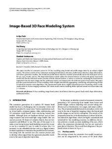
Figure 1. Estimated 3D model from multi-views. From L-to-R: one view, estimated shape, estimated texture-map, reconstruction. ette projection of the object from a viewpoint which represents a range of similar nearby views in the space of uniformly sampled view-sphere. We use a similar technique to reduce the size of the view space except we only have one object class. After uniformly sampling the view-sphere and applying high-level model-specific constraints such as facial symmetry, we generate view clusters by merging nearby view cells using a silhouette similarity metric and pick the prototypical “centroids” of each cluster as our aspect views. Any combinatorial subset of these aspect views constitutes a candidate multi-view configuration.
our shape model and their associated eigenvalues (the variances of their implicit Gaussian distribution). This decomposition can be used to reconstruct a new or existing face through the linear combination of “eigenhead” basis functions [2]. An inspection of the PCA eigenvalue spectrum and the resulting shape reconstructions indicated that the first 60 eigenheads were quite sufficient for capturing most of the salient facial features of the subjects in our database. The corresponding αi shape coefficients were therefore our optimization parameters. Specifically, let M(α) be any arbitrary face model which produces a polygon mesh given a paramk eter vector α = {α1 , α2 , · · · , αn }. Let Sinput , k = 1..K be kth input silhouette image. Also, let T be a similarity transformation that aligns a reference model face to the real 3D face. k Then, Smodel (α) is a silhouette image rendered by projecting T (M(α)) onto an image plane using the pose information in the kth silhouette image. The parameter vector α is estimated by minimizing the total penalty K
E(α) =
2. Multi-View 3D Face Modeling In previous work [8, 6], we introduced a model-based shape-from-silhouette method for capturing 3D face models using multiple calibrated cameras. 1 Figure 1 shows one such 3D model obtained from a novel subject inside a special multi-view rig (dome). In this case, the “right” camera configuration was found after some trial and error and using our “intuition” as to which views are informative for shape capture. In this paper, our goal is to essentially remove the guess-work from the view selection process and determine the optimal geometry (view configuration) for a given number of cameras (here we focus on estimation of 3D shape only). Our optimization framework allows the user to easily incorporate existing physical constraints into the optimal view selection process. In this section we briefly review our 3D modeling methodology (for further details the reader is referred to [8]). For model building we used the USF “HumanID” dataset [1] of 3D Cyberware scans of 97 male and 41 female adult faces of various races and ages. The number of points in each face mesh varies from approximately 50,000 to 100,000. All faces in the database were first resampled to obtain point-to-point correspondence and then aligned to a reference face to remove any pose variation and/or any misalignment (during the scan). We then perform PCA on the database of aligned 3D faces to obtain the eigenvectors of 1
Unlike “morphable models” [3], our 3D modeling technique treats shape and texture independently and is hence robust w.r.t. lighting and texture variations. Furthermore, our silhouette-matching optimization is simpler, has fewer free parameters and is considerably faster (x20).
k k , Smodel (α)) ∑ f (Sinput
(1)
k=1
where the cost function f measures the difference between two binary silhouettes. For the cost function f in Eq.(1) the simplest difference metric between two (binary) silhouettes is the number of ‘on’ pixels when a pixel-wise XOR operation is applied. But in order to prioritize matching the right pixels (on the occluding contours) and to promote uniqueness so f has a global minimum, we must impose a higher penalty for any mismatch near the boundary pixels of the input silhouette. Specifically, H W
k k f (Sinput , Smodel (α)) = ∑ ∑ c(i, j) i
� c(i, j) =
0 d(i, j)−2
(2)
j
k k if Sinput (i, j) = Smodel (α)(i, j) otherwise.
d(i, j) = D(Sk )(i, j) + D(S˜k )(i, j), where D(S) is the Euclidean distance transform of binary image S and S˜ is the inverse image of S. Note that d represents a distance map from the silhouette contour and can be computed once in a preprocessing step. We call this cost function boundary-weighted XOR, which provides a simple and effective alternative to precise contour matching. Consequently, there is no need for expensive correspondences with edge-linking, curve-fitting and distance computations between contours. Furthermore, the (weighted) XOR operations can be performed in hardware. Given the inherent complexity (and nonlinearity) of the cost function (and no analytic gradients) we used a probabilistic downhill simplex method to minimize Eq.(1).
Figure 3. Building a (complete) subject using a prototype head. Figure 2. Originals (top) and reconstructions (bottom) for minimum (left), median (middle) and maximum L2 error (right). To illustrate our 3D shape modeling accuracy, we chose 50 real faces from the database and an additional 50 synthetic (novel) faces generated by randomly sampling the implicit Gaussian prior distribution of the PCA model. In this case, 11 virtual cameras were then positioned in the front hemisphere around the subject. The input silhouette images were acquired by rendering each of the sample faces in the image planes of the 11 virtual cameras. Figure 2 shows a visualization of the distribution of reconstruction errors obtained. The selected faces in the figure correspond to the minimum, median, and the maximum L2 error among all 100 (real and virtual) samples. The important thing to note is that our silhouette-based technique captures the most important facial features with relatively high accuracy even in the worst-case scenario with a real subject (3rd column).
3. Methodology We now present the experimental protocol used to find optimal views for an arbitrary number of cameras K (up to 5). We illustrate how to prune the space of all possible views obtained by uniform tessellation of the view-sphere based on clustering adjacent view cells using silhouette similarity (from shape projections). The selected set of aspect views is then investigated using both our model-based approach and a data-driven visual hull method.
3.1. Silhouette Generation The silhouettes of a resampled face in our database are quite different from the silhouettes captured from actual subjects (due to the missing portion of the head/torso). To simulate silhouette images of actual subjects with our database, we use a fully scanned 3D head as our prototype head/torso, shown in Figure 3. We align the facial region of the prototype head to a resampled face (by smooth deformations) and then “stitch” the two together to synthesize a “virtual” test subject complete with full head and shoulders. Therefore, we can generate complete silhouette images with
Figure 4. Uniform tessellation of view-sphere (left). Remaining view cells left after imposing practical imaging constraints (right). the same exact face shapes as in the database while maintaining the proper geometry of complete subjects.
3.2. View-sphere Tessellation We first tessellate a view sphere uniformly using a subdivision from a dodecahedron around the subject. This procedure yields 120 triangles (we call them view cells) whose vertices are on the surface of the view sphere as shown in Figure 4. We discard all the view cells in the rear-half of the view-sphere since the face is occluded from their vantage point. We further discard the view cells which are too high/low in elevation, since these are unlikely and/or impractical physical locations for a real camera. Furthermore, from such oblique views it is hard to capture facial contour due to the occlusion (and resulting confusion) by the subject’s hair and shoulder. In our case we restrict the elevation of view cells to ±45◦ . Finally, assuming (approximate) bilateral symmetry of human faces, we discard the entire left-half of the remaining view cells, ending up with the 44 view cells shown in Figure 4 (right).
3.3. Clustering Views The remaining 44 view cells result in too many combinations (subsets) of views. For example, to find 11 optimal views by an exhaustive search there are approximately 7 × 10⁹ view combinations to evaluate which is quite intractable. Therefore, we need to reduce the search space
Table 1. Aspect View Coordinates View # 1 2 3 4 5 6 7 8 9 10
Azimuth◦ 3.4 7.6 28.2 31.4 40.0 48.3 52.2 55.1 63.1 85.9
Elevation◦ 40.4 -15.5 -17.0 18.9 0.9 -16.5 16.8 39.4 -30.2 17.7
Figure 5. The 10 silhouette clusters and their corresponding aspect views shown on the view sphere surrounding a test subject. even further. Our observation is that the silhouette images of two neighboring view cells can be quite similar. Therefore, we measure the silhouette difference and merge view cells within a certain distance and represent the merged view cells with one view (centroid). We consider only the silhouette difference around the critical facial area since face shape recovery is not affected by the silhouette differences in other areas (head/shoulders). For clustering, we first build a lookup table (D) that contains the partial or face-restricted XOR distance between every two view cells in the search space. Initially, every view cell is considered a cluster and the aspect view of the cluster is the view cell itself. We define the distance of two clusters by the distance of their aspect views and that information is pre-computed and stored in D. We find the two neighbor clusters that have the minimum distance among all the other neighbor clusters and merge them. After merging two clusters, we compute a new aspect view for the new merged cluster. The new aspect view is the view cell which has the minimum value for the maximum distance to all the other view cells in the same cluster. We repeat this process until the desired number of clusters remain. Figure 5 shows 10 clusters and their aspect views obtained using this clustering procedure. Note that the resulting aspect views are not necessarily geometric centroids of clusters, rather view cells with minimum silhouette distance to other cluster members. To circumvent any subject-dependency and generalize this clustering, all the entries in our lookup table D were created by averaging the pair-wise view cell distances for 50 different synthesized heads in our database. Table 1 gives the coordinates of the aspect views wherein azimuths of {−90◦ , 0◦ , +90◦ } correspond to {left, front, right} directions in a head-centered reference frame. Figure 6 shows the silhouettes obtained from the 10 as-
Figure 6. Silhouettes from the 10 aspect views. pect views along with the model silhouette (in blue) and the critical facial area used for error evaluation (in cyan). All L2 reconstruction errors were confined to the critical facial area only so as to ignore extraneous input from hair/head. We discard view #1 since from its downward angle the face silhouette is completely hidden/confounded by the torso, as well as view #2 since frontal views offer very little occluding contour as constraints for shape recovery (although frontal views are preferred for capturing texture).
3.4. Finding Optimal Views Given the remaining 8 aspect views, we must exhaustively search for the optimal subset of K ≤ 8 views which (in each case K) yield the closest 3D shape reconstruction with respect to the original face, using the K silhouettes for the shape recovery process. We have searched up to K = 5, although there is experimental evidence to suggest that going beyond this one may encounter diminishing returns. The default reconstruction method is our model-based (eigenhead) 3D face shape recovery method [8, 6]. By way of comparison, we also tested a purely data-driven method using visual hull construction. It should be noted that visual hulls by themselves are not very capable of accurate reconstructions (even with hundreds of views). Our goal was to show that a greedy search based on a data-driven technique will select a similar set of optimal views.
Table 2. Optimal views based on model-based reconstruction. K 1 2 3 4 5
Best Views 4 3, 10 3, 5, 10 3, 4, 9, 10 3, 4, 7, 8, 10
Best Error 40.7 31.9 28.2 26.8 26.6
Subject Std. Dev. 12.4 8.6 6.1 6.2 7.1
Error Mean 45.0 37.6 33.9 31.7 30.2
Error Std. Dev 3.3 4.3 3.7 2.9 2.2
For the optimal views to be relevant for general purpose face modeling and recognition, they must apply for generic faces of all kinds (gender, ethnicity, age). Therefore optimality should be independent of the subject. To this end, we used a representative subset of 25 individuals from our database and based our optimal view selection on the configurations that minimized the total or averaged error for all 25 subjects. When we recover a 3D shape from silhouette images, we require a metric that measures the error between the ground truth and the reconstructed 3D geometry. Since our focus is on the facial area of the recovered shape, we need a metric that measures the difference in the critical facial area of the recovered shape and the original face. The basic approach for this error measurement is as follows: The first step is to find a dense point set on the facial area of the recovered face geometry. With an eigenhead shape model we can easily find those facial points for our model (via the mesh parameterization). However, it is not trivial to find the same facial points on a visual hull. We use a ray casting scheme to find the facial points on the visual hull. Since we have the original 3D heads which we use to generate the input silhouette images, from facial points on the original head, we cast rays toward the visual hull and get the corresponding samples on the surface of visual hull. After we get the facial points we use the same ray casting scheme to get the corresponding samples on the surface of a ground truth mesh. We measure the L2 distances of the facial points on the recovered face and the corresponding points on the ground truth and use them as the 3D error metric for the facial area. 3.4.1. Model-Based Reconstructions. We performed the exhaustive search on the 8 aspect views in Figure 6 to find the optimal subset of views for K = {1, 2, 3, 4, 5} cameras. To remove the data dependency inherent in a single individual’s reconstruction error, we used the ensemble (average) reconstruction error of 25 random subjects from the database. Therefore, the total number of reconstructions is 25 · ∑5K=1 CK8 = 5450. Based on an average reconstruction time of 30 seconds, this search takes about 45 hours. The results are presented in Table 2 which shows the optimal views for K = {1, 2, 3, 4, 5} and the corresponding minimum average reconstruction errors (refer to Table 1 for exact coordinates). The standard deviation of the indi-
Figure 7. Reconstruction errors for all view configurations (K = 4) ranked by magnitude of ensemble error. Error bars indicate the standard deviation of error among the 25 subjects. vidual errors for all 25 subjects under the best configuration is also shown. The average error means and average error standard deviations (last two columns) are based on the average reconstruction errors across all views and both tend to decrease with increasing K (as expected since more views provide more constraints). Comparing the two different standard deviations, we note that this method is less view-dependent and more subject-dependent. What this table does not show, however, is the distribution of reconstruction errors across various view configurations (and their individual subject variation). Figure 7 shows the errors of all combinatorial view configurations for the case K = 4, ranked in ascending order of error. Each error bar represents the subjects standard deviation for that configuration (the first error bar corresponds to the optimal configuration and is the subject standard deviation listed in Table 2). Other plots for K = 1, 2, 3 and 5 are quite similar in nature, all showing a well-defined minimum with the subject variation (error-bars) being lowest for the best configuration (left most) and highest for the worst (right most). In the next section, we will compare this graph to the corresponding ones obtained from visual hull construction, where the global minimum is not so well-defined (due to lack of constraints in a purely data-driven approach). 3.4.2. Visual Hull Reconstructions. Using the same search strategy, we now evaluate the visual hull constructions obtained from the given subset of silhouette images and compare them to the ground truth. Table 3 shows the optimal views for K = {2, 3, 4, 5} and the corresponding error values (same format as in Table 2 except that the visual hull from a single silhouette (K = 1) has no finite volume and is omitted). Note that a visual hull reconstruction (especially one from few images) is not a very accurate representation and we are only focusing on the op-
Table 3. Optimal views based on visual hull reconstruction. K 2 3 4 5
Best Views 3, 10 3, 9, 10 3, 8, 9, 10 3, 4, 8, 9, 10
Best Error 418.7 406.0 399.9 398.3
Subject Std. Dev. 26.1 24.7 25.8 25.5
Error Mean 847.7 643.5 541.0 481.2
Error Std. Dev 400.4 246.9 163.3 108.9
Figure 8. Reconstruction errors for all view configurations using visual hulls. timal views selected (regardless of their high error). Unlike the model-based results, here the reconstruction quality is much more view-dependent than subject-dependent. However the view dependency decreases significantly as the number of views (K) increases (see the error standard deviations). The graphs in Figure 8 show the errors of all view configurations at K = {2, 3, 4, 5}. In all 4 graphs, we note the presence of “plateaus” where the error is nearly constant for a large number of configurations. Interestingly, the first plateau corresponding to the top “group” is all the subsets which include the profile view #10 (one of the most salient). We can see marked similarities in the optimal views in Table 2 and Table 3. For example, both methods indicate views #3 and #10 to be the most informative. There are a few differences but these are somewhat misleading. The best view configurations in Table 2 are marked in Figure 8 with arrows. Note that the optimal views chosen by the model-based selection have nearly the same error as the best views chosen by the visual hull method and that they are always in the first plateau or top quartile which includes the most salient (profile) view #10.
4. Conclusion Our work presents the first systematic investigation of optimal views for 3D face modeling (in particular using shape-from-silhouettes). These findings should provide use-
ful guidelines for designing future 3D face recognition systems and are in agreement with existing practice and intuition. For example, the two most salient views (#3 and #10) correspond very closely with the established (biometric) standards of “3/4 view” (INS photos) and profile view (“mugshot” photos). We have not yet searched for K > 5 mainly due to the computational costs, but it appears that reconstructions do not improve significantly beyond 4-5 views (see the best errors listed in Table 2). One can easily incorporate additional physical and operational constraints into our framework. For example, although a frontal view is not very salient for shape, it is the preferred view for capturing texture-maps (hence its prevalence in nearly all 2D face recognition systems) and it can be simply pre-selected before the search. Finally, video-based capture – where subject motion (pose variation) provides multiple (virtual) views – is essentially equivalent to the static multi-view case and we have previously used our technique (Figure 1) with monocular sequences [8] but with heuristic pose selection (silhouette-clustering with k-means). Based on these new findings, we can now track a moving subject and automatically select the optimal poses (video frames) that are best for 3D modeling and recognition.
References [1] USF HumanID 3D Face Database, Courtesy of Sudeep Sarkar, University of South Florida, Tampa, FL. [2] J. J. Atick, P. A. Griffin, and N. Redlich. Statistical approach to shape from shading face surfaces from single 2D images. Neural Computation, 8(6):1321–1340, 1996. [3] V. Blanz and T. Vetter. Face recognition based on fitting a 3D morphable model. PAMI, 25(9), 2003. [4] C. M. Cyr and B. B. Kimia. 3D object recognition using shape similarity-based aspect graph. In Proc. of ICCV, pages 254–261, 2001. [5] P. Fua. Regularized bundle-adjustment to model heads from image sequences without calibration data. International Journal of Computer Vision, 38(2):153–171, 2000. [6] J. Lee, B. Moghaddam, H. Pfister, and R. Machiraju. Silhouette-based 3D face shape recovery. In Proc. of Graphics Interface, pages 21–30, 2003. [7] K. Lee, J. Ho, and D. Kriegman. Nine points of light: Acquiring subspaces for face recognition under variable lighting. In Proc. of CVPR, pages 519–526, 2001. [8] B. Moghaddam, J. Lee, H. Pfister, and R. Machiraju. Modelbased 3D face capture using shape-from-silhouettes. In Proc. of Advanced Modeling of Faces & Gestures, 2003. [9] F. Pighin, J. Hecker, D. Lischinski, R. Szeliski, and D. Salesin. Synthesizing realistic facial expressions from photographs. In Proceedings of SIGGRAPH 98, 1998. [10] Y. Shan, Z. Liu, and Z. Zhang. Model-based bundle adjustment with application to face modeling. In Proceedings of ICCV 01, pages 644–651, July 2001. [11] R. Szeliski. Rapid octree construction from image sequences. CVGIP: Image Understanding, 58(1):23–32, 1993.