Alex H. Lumpkin and Bingxin Yang. Advanced Photon ..... 144â146 (1992). [7] Yang, B. X., A. H. Lumpkin, G. A. Goeppner, S. Sharma, E. Rotela, I. C. Sheng,.
First Multi-GeV Particle-Beam Measurements Using a Synchroscan and Dual-Sweep X-ray Streak Camera† Alex H. Lumpkin and Bingxin Yang Advanced Photon Source Argonne National Laboratory Argonne, IL 60439 USA
Abstract. Particle-beam characterizations of a multi-GeV storage ring beam have been done for the first time using a synchroscan and dual-sweep x-ray streak camera at the Advanced Photon Source (APS). The hard x-rays (2–20 keV) from a bending magnet source were imaged using an adjustable pinhole aperture. Both the horizontal size, σx ~ 190 µm, and bunch length, σt ~ 28 ps, were measured simultaneously. The Au photocathode provides sensitivity from 10 eV to 10 keV covering the three orders of magnitude in wavelength from the UV to hard x-rays.
INTRODUCTION As interest grows in the development of diffraction-limited x-ray sources, the challenges for particle beam diagnostics and the need for demonstration of measurement capability have been identified (1, 2). The general concept of a diffraction-limited source at 1 Å and the corresponding target particle beam parameters of σx,y ~ 10 µm, σx′,y′ ~ 1 µrad (for β = 10m), and σt ~ 1 ps to 0.1 ps have been noted. Fortunately, the present third-generation synchrotron radiation facilities can provide a test bed for some of these parameters in one plane by the use of low-vertical coupling (3). We have imaged the 7 GeV stored positron beam at the Advanced Photon Source (APS) using hard x-ray synchrotron radiation (XSR), an adjustable pinhole aperture, and a unique synchroscan/dual-sweep x-ray streak camera. Both transverse beam size and bunch length have been determined. Much as the visible single-sweep streak cameras were extended to the soft x-ray regime in the 1970s (4), the synchroscan and dual-sweep fea-
† Work supported by the U.S. Department of Energy, Office of Basic Energy Sciences, under Contract No. W-31-109-ENG-38.
tures of the late 1980s visible streak cameras (5,6) have now been extended to the x-ray regime. Potentially, the XSR can provide better spatial resolution than visible radiation by a reduced contribution from the diffraction limit. The potential for characterizing the smaller beam sizes of lower emittance beams in the picosecond regime can assist R&D with third-generation sources towards the next-generation sources.
EXPERIMENTAL BACKGROUND The APS is a third-generation hard x-ray synchrotron radiation facility. Its main parameters include a 7 GeV beam energy, 100 mA stored beam current and a 8.2 × 10⁻⁹ m rad natural emittance. Other parameters are listed in Table 1. Measuring and monitoring the beam quality is one of the missions of the Diagnostic Group of the Accelerator Systems Division. To this end, one of the forty sectors in the ring is dedicated to particle-beam diagnostics using both optical synchrotron radiation (OSR) and XSR (7). In the past, we have measured head-tail kicks in a micropulse (8), bunch length versus single-bunch current (9), and other beam dynamics issues (10). As we push towards lower vertical coupling in the facility to enhance x-ray beam brilliance over the original 10% coupling baseline, the vertical particle beam size becomes less than 50 µm at 1–2% coupling and even smaller at 0.1% coupling, the long-range target. Due to diffraction effects, it is very difficult to image these beam sizes using OSR. The diagnostic sector was planned to support these long range developments. A part of this plan is the development of a beamline that transports undulator radiation and dipole radiation from both a dispersive and nondispersive point in the lattice. In this experiment the x-ray streak camera was positioned 27 m from the dipole source as schematically indicated in Figure 1. The adjustable pinhole, based on a remotely controlled fourjaw aperture, was located 10.1 m from the source point, resulting in a magnification of 1.67 at the photocathode (PC) of the x-ray streak camera. TABLE 1. Accelerator Parameters for Diagnostics Parameter Energy (GeV) rf freq. (MHz) Harmonic no. Min. bunch spacing (ns) Rev. period (µs) No. of bunches Design max. single bunch current (mA) Bunch length (2σ) (ps) Damping times τh,v (ms) Tunes νh,νv
Storage Ring 7 351.93 1296 2.8 3.68 1-1296 5 35-100 9.46 35.22, 14.30
Damping time τs (ms)
4.73
Synch. freq. fs (kHz)
1.96
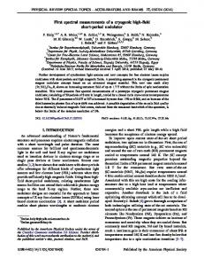
FIGURE 1. A schematic of the Sector 35 ID and dipole sources and the locations of the x-ray streak camera and adjustable pinhole.
An important practical aspect of the set-up was the remote-controlled positioning of the camera using three stacked translation stages as shown in Figure 2. These stages were under the mainframe and provided x-, y-, and z(t)-axis motion. This facilitated the alignment of the Au strip photocathode (6 mm (H) × 50 µm(V)) to the x-ray pinhole image field. Coarse alignment was done with the standard “burn paper” mounted on the front flange of the camera.
FIGURE 2. A photograph of the x-ray streak camera mounted on the three translation stages for x-, y-, and z(t)-axis motion. The front window is a Be. The streak tube vacuum is obtained with the external ion pump.
The Au photocathode allows detection of radiation from at least 10 eV to 10 keV and has some efficiency at energies up to 20–25 keV (see Figure 3). The soft x-rays are strongly attenuated by the Be windows in the transport. The x-ray tube is housed in a mainframe compatible with the plug-in units of the Hamamatsu C5680 series (11). For these experiments the synchroscan plug-in provided the vertical (fast time) sweep and the M5679 unit the horizontal (slow time) sweep. Although x-ray streak tubes with single fast deflections have been used for years in other fields (4), to our knowledge these are the first data taken on an accelerator or synchrotron radiation facility with the vertical sweep of the x-ray tube locked to the accelerator’s rf frequency subharmonics, with repetition speeds greater than 100 MHz (117.3 MHz) and with jitter less than 1 ps. A second, orthogonal set of deflection plates in the tube was also used for a dual-sweep demonstration down to 200 µs, which was limited by photon intensity in this configuration. The use of x-rays for imaging also reduces the resolution limit from diffraction effects compared to optical (visible) synchrotron radiation (OSR) imaging, so that some beam dynamics issues may be addressed at smaller spot sizes.
FIGURE 3. An estimate of the absorbed power in percent by the Au photocathode of the x-rays spectral distribution (in keV) from the bending magnet source. The attenuation of the soft-x-rays by the beamline exit Be window and the x-ray tube’s entrance Be window has been included.
RESULTS In this section we will address some of our first results in using the x-ray camera to image the 7 GeV particle beam. From these images both spatial and longitudinal information were obtained. Since the bending magnet source point was from an essentially nondispersive location in the lattice, no energy spread effects contribute to the horizontal or vertical beam size. The first practical problem was to properly position the streak camera’s slit photocathode in the sub-mm-sized x-ray beam. After a coarse mechanical height adjustment, better alignment was done with the standard “burn paper” mounted on the front flange of the camera. A Hg lamp was used then to illuminate the photocathode via a window
and internal mirror to verify all voltages were applied and the PC was intact. As shown in Figure 4(a), the UV light irradiated the slit photocathode, and the image indicated a basically uniform response. The static spread function of the tube for UV light is found to be 4.5 channels (FWHM) and supports our previous sub-ps resolution test using a laser (12, 13). We then set the x-ray pinhole apertures at 50 × 50 µm2 and scanned the vertical plane using the remotely-controlled translation stage. As shown in Figure 4(b), the effective static spread function in the hard x-ray field resulted in a y-profile size of 9.1 ch (FWHM). The larger size is due to the physical limitations of focusing the feweV energy spread of the photoelectron emitted from the Au’s interaction with few-keV photons (4). Figures 4(a) and 4(b) graphically illustrate one of the issues for obtaining ps-resolution for an x-ray streak camera. For a vertical deflection speed of 0.31 ps/ch on the fastest range, the UV time resolution is about 1.5 ps (FWHM) or 0.6 ps (σ), and the hard x-ray resolution is estimated at 2.8 ps (FWHM) or about 1.2 ps (σ). The latter resolution is still sufficient to characterize the presently estimated limits of future storage ring beam bunch lengths.
FIGURE 4. Images from the x-ray streak tube in focus mode: (a) the Hg UV light source, (b) the bending magnet x-ray source on the Au PC, and (c) the x-ray incident off the y-location of the Au PC.
During the course of vertical scanning for the Au PC we observed a much weaker, full image when the streak camera was located about ±1 mm from the strip photocath-
ode position. By increasing the external microchannel plate (MCP) gain (×100), we obtained what appears to be the full spatial pinhole images of the particle beam. In Figure 4(c), the y-profile size of 22.5 ch (FWHM) corresponds to about 100 µm (FWHM) at the source point or 43 µm (σ). The x-profile is about 190 µm (σ) at the source point. These sizes are consistent with low vertical coupling (1–2%) in the ring. The synchroscan streak ranges were next exercised. Three of the four were tested with x-rays. The phase adjustment was done using the z-translator instead of an rf phase-delay unit. A validation of the camera calibration was also executed by acquiring data at different z(t) locations from the source. The centers of the streak images were determined for each z(t) position, and the calibration factors were found to be within 5% of the factory calibration performed with a different method. On a subsequent run with the aperture at 100 × 100 µm2, the focus mode image is shown in Figure 5(a), and in Figure 5(b) the synchroscan image with the observed bunch length of 65 ps (FWHM) or 28 ps (σest) is seen. On this streak deflection range the camera resolution is estimated from the focus mode image size (static spread function) to be σres ~ 4 ps. The fastest range available is about four times faster.
FIGURE 5. X-ray streak camera images of the particle beam (a) focus mode, and (b) synchrotron streak mode with 4 ps resolution. The observed bunch length is σt = 28 ps.
In Figure 6 we show a test of (a) the single horizontal sweep function and (b) the dual-sweep with a 10 ms horizontal by 500 ps vertical coverage. In this latter case the phase tilt upward going from left to right is an instrumental alignment effect (since it is also in 6(a)). The modulation of the bunch intensity on the few-ms timescale is attributed to vertical beam motion on and off the slit PC or a longitudinal effect in the beam. Source strength issues need to be evaluated, but shorter time samples might be done
with an undulator source instead of a single dipole magnet and by using less magnification to increase the signal per pixel. The present case involves the nominal 80 mA stored positron beam. We have obtained images with a 100 times smaller pinhole aperture so bunch length measurements of less than 1 mA should be possible. This would address the realm of single-bunch, multiple-turn data in our ring.
FIGURE 6. Examples of x-ray streak images: (a) a focus mode with single, 100 ms horizontal sweep on and (b) a dual-sweep with 10 ms horizontal time axis coverage and 500 ps vertical coverage (synchroscan). Some modulation of the intensity on the few-ms timescale in (b) is evident.
SUMMARY In summary, we have performed initial measurements of a multi-GeV beam with hard XSR (2-20 keV) using a unique x-ray streak camera. Both beam transverse size and bunch length measurements are possible simultaneously. This capability should extend studies of beam dynamics in small beams. Additionally, this technique addresses the need identified for ps-domain x-ray detectors for time-resolved experiments using 10 eV to 10 keV radiation for user experiments (14).
ACKNOWLEDGMENTS The authors acknowledge the support of John Galayda and Glenn Decker of the APS Accelerator Systems Division and the assistance of William Cieslik of Hamamatsu Photonics Systems.
REFERENCES [1] [2] [3] [4] [5] [6] [7]
[8] [9] [10]
[11] [12] [13] [14]
Lumpkin, A. H., “On the Path to the Next Generation of Light Sources,” Nucl. Instrum. Methods in Phys. Res. A 393, pp. 170–177 (1997). Lumpkin, A. H., “Beam Diagnostics Challenges for Future FELs,” Proceedings of the SPIE’97 FEL Challenges Conference, SPIE Vol. 2988, p. 70 (1997). Lumpkin, A.H. and Bingxin X. Yang, “Measurements of Near-Prototypical Fourth Generation Light Source Beam Parameters,” submitted to Phys. Rev. Letters, April 1998. Stradling, G., “Soft X-ray Streak Cameras,” Proc. of the 18th International Conference on High Speed Photography and Photonics, SPIE Vol. 1032, p. 194 (1988). Lumpkin, Alex H., “Advanced Time-Resolved Imaging Techniques for ElectronBeam Characterization,” Proc. of the Accelerator Instrumentation Workshop, AIP Conf. Proc. 229, p. 151 (1991). Rossa, E., C. Bovet, L. Disdier, F. Madeleine, and J. J. Savioz, “Real-time Measurement of Bunch Instabilities in LEP in Three Dimensions using a Streak Camera,” Proc. of the Third European PAC, Vol. 1, pp. 144–146 (1992). Yang, B. X., A. H. Lumpkin, G. A. Goeppner, S. Sharma, E. Rotela, I. C. Sheng, and E. Moog, “Status of the APS Diagnostics Undulator Beamline,” Proc. of the 1997 Particle Accelerator Conference (held May 12–16, 1997, Vancouver, BC, Canada), to be published. Lumpkin, Alex H., “Time-Domain Diagnostics in the Picosecond Regime,” Proc. of the Microbunches Workshop, Upton, NY, Sept. 1995, AIP Vol. 367, p. 327 (1996). Lumpkin, A. H., B. X. Yang, and Y. C. Chae, “Observations of Bunch-lengthening Effects in the 7-GeV Storage Ring,” Nucl. Instrum. and Meth. A 393, pp. 50–54 (1997). Yang, B. X. et al., “Characterization of the Beam Dynamics in the APS Injector Rings Using Time-Resolved Imaging Techniques,” Proc. of the 1997 Particle Accelerator Conference, (held May 12–16, 1997, Vancouver, BC, Canada), to be published. Hamamatsu Photonics, C5680 Universal Streak Camera Data Sheet, May 1993. Lumpkin, A. H., B. Yang, W. Gai, and W. Cieslik, “Initial Tests of the Dual-Sweep Streak Camera System Planned for the APS Particle-Beam Diagnostics,” Proc. of the 1995 PAC (Held Dallas, TX, May 1–5, 1995), Vol. 4, p. 2476 (1996). Lumpkin, A., Nucl. Instr. and Methods A 375, p. 460 (1996). Knotek, M. (Ed.), Presented at the Workshop on Scientific Opportunities for Fourth-Generation Light Sources, Argonne National Laboratory, October 27–29, 1997.