Feb 4, 2007 - {yanagida, akitake, maeda, tachi}@star.t.u-tokyo.ac.jp. Abstract ..... tracker system with 6 degrees of freedom (Shooting Star. ADL-1) and the ...
ICAT '99 Implementation of Fixed-screen-based Telexistence Visual System Yasuyuki Yanagida, Akitake Mitsuhashi, Taro Maeda and Susumu Tachi Dept. of Mathematical Engineering and Information Physics, School of Engineering, The University of Tokyo 7-3-1 Hongo, Bunkyo-ku, Tokyo 113-8656 JAPAN {yanagida, akitake, maeda, tachi}@star.t.u-tokyo.ac.jp
Abstract Visual display systems based on Immersive Projection Technology, such as CAVE and CABIN, are expected to be effective platforms for VR applications. However, these kinds of visual displays, as well as other kinds of fixed-screen-based display systems such as head-tracked displays (HTD) and conventional CRT displays, have not been utilized for exact telexistence in real environment, which requires appropriate stereoscopic image sequences corresponding to the operator’s head motion. We found that the time-varying off-axis projection required for generating displayed images has been prevented these kind of fixed screens from being used for telexistence, as ordinary cameras have symmetric field of view about the optical axis. We solved this problem by equivalently realizing the off-axis projection by the combination of ordinary symmetric projection and simple 2dimensional image manipulation. We propose several types of implementation scheme according to which part of this image manipulation is taken place after the cameras capture the original image. The key element to construct the system based on our proposed method is to keep the orientation of the cameras, regardless of the operator’s head orientation. We realized this feature by designing a constant-orientation link mechanism. The prototype of the constant-orientation link could follow the operator’s natural rotational head motion. Key words : telexistence, immersive projection technology, head-tracked display, off-axis projection
1. Introduction Visual display systems based on Immersive Projection Technology (IPT), such as CAVE [1], CABIN [2], and so on, are expected to be effective platforms for VR applications, as the visual quality provided by those systems is considerably high. It is often mentioned that the visual quality of IPT is provided by the large field of view obtained by large screen and by the high resolution per screen by using high-resolution graphics computers. Moreover, it is considered that visual display systems
which use screen(s) fixed to the surrounding environment have some merits of the stability of the displayed image when the operator move his/her head. The angular error of the points in the displayed image, which is caused by the tracking error or the latency of the system, was analyzed to examine the stability of the image provided by a projection-based VR display [1]. In this analysis, the result was compared for Head-Mounted Displays (HMD), CRT and CAVE, which showed that there are significant advantages in fixed-screen paradigm (CRT and CAVE) over the HMD, when rotational tracking error exists. This result is inherently derived from the characteristics of fixed-screen-based displays, in which the pure rotation about the observation point does require the displayed image to be updated. The similar analysis was reported [3] focusing on the effect of inevitable time delay through the whole system on the HMD. In spite of these merits, fixed-screen-based displays have not been utilized for exact telexistence/telepresence in real environment. So far only HMDs have been used for the visual display systems in telexistence/telepresence systems, such as TELESAR [4, 5], TOPS [6], and so on. IPT displays have been used only as large- or multiscreen monitors, when images of the real world are displayed, or they have enforced inexact stereoscopic view upon the user even if the user’s head motion is tracked. This is a common aspect for conventional CRT displays and projection displays with a single screen, as well as for IPT displays. In order to provide the operator with exact threedimensional sensation of presence by the cue of disparity and convergence, we have to design the system such that the projection used at the remote site (camera) and that of the operator’s site are kept consistent. In other words, the shape of the viewing volume at both sites should coincide with each other. We noticed that there are no camera systems that provide the viewing volume corresponding to that of the display systems using fixed screens, and found that this is the key to realize the exact telexistence/telepresence visual system using fixed
(from view points)
Left eye Right eye
(from view points)
Left eye Right eye
(a) Shape of the viewing volume
(a) Shape of the viewing volume
Object
Object
Matching point
Matching point
Image of screen
Screens are fixed to the head
Head translation and rotation
Image is displayed onto entire screen
Screen
Shape of the viewing volume varies
Translation and rotation
Projection is constant
(Original location)
Origin
Origin
(b) Head motion at the operator’s site
(b) Head motion at the operator’s site
Object
Object Matching poing
Image plane
Matcing point
Screens are fixed to the head
Translation and rotation Origin Robot head
Screens is fixed to surrounding space
(Original location)
Image plane is equivallently fixed to world coordinate
Image plane
Projection is constant
Cameras are fixed to the head
(c) Head motion at the remote site
Figure 1 Projection for HMD system screens. In this paper, a method of constructing exact stereoscopic telexistence system and a prototype system based on the method is described.
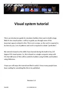
2. Analysis of the Problem 2.1 Projection for HMD and Fixed Screen As we mentioned above, the projection transform used for generating (capturing) images at the remote site and that for displaying the image at the operator’s site should coincide with each other. This projection transform depends on the type of the display device/system. To make this clear, we compare the projection transform used for HMD and fixed-screen-based system. The shape of the viewing volume for typical HMD is shown in Figure 1 (a), and the treatment when the operator’s head moves is shown in (b). Most typical HMDs are designed such that the image of the screen is parallel to
Translation and Rotation Origin Robot head
Controlling offset of the field of view and zooming ratio Orientation of the camera keeps constant
(Original location)
(c) Head motion at the remote site
Figure 2 Projection for fixed-screen-based system (Type A: off-axis projection, used for CG) the operator’s forehead and the field of view is symmetric about the optical axis. In this case, the shape of the viewing volume is a regular pyramid and constant, as the screens of HMD are fixed relative to the operator’s head. Considering these characteristics, we can use normal cameras fixed to the robot head, arranged such that the distance between two cameras is identical to that of the operator’s eyes (Figure 1 (c)). The operator can feel natural three-dimensional world around him/her, if the position and orientation of the robot head is controlled to follow the operator’s head. On the other hand, off-axis projection [7], also known as the function glFrustum() in OpenGL API [8], is used for fixed-screen-based systems as shown in Figure 2 (a). The shape of the viewing volume is a general frustum and the optical axis does not point the center of the screen. When the operator moves his/her head, the shape of this frustum varies according to his/her motion in real-time, as
P (x p, y p, z p)
P(xp, yp, zp)
SL
SR
D E θ
EL E
R
Screen
ER
O
x
L
z
d
Direction of Head
(a) Effect of rotation Center of eyes
P(xp , y p, zp )
P (x p, y p , z p )
1m
Figure 4 Distortion caused by non-head-tracked image SL
tional head motion, and (b) shows the case with translational motion. In each figure, the left and right eyes are located at the point ER and EL, respectively, and the image of point P is projected at the point S R and S L on the screen. The operator’s head is directed to the screen at the initial state. The inter-pupil distance of the operator is denoted as d, and distance between the center of the eyes and the screen is denoted as D.
SR SM
D E EL
E L
R
O O
ER
d
x
z
(b) Effect of translation
Figure 3 Distortion of the world caused by non-tracked image shown in Figure 2 (b). It is easy to control the shape of this frustum when generating computer graphics images, as we can specify the parameters of this frustum whenever we start drawing of the image for each frame. However, We cannot apply this scheme for obtaining real-time video image, as such off-axis projection is not popular for cameras and controlling the shift amount and the angle of field of view is rather difficult.
2.2 Necessity of Head Tracking Even though a fixed-screen system can provide stable image corresponding to the operator’s head motion, head tracking is still important. Let us consider the situation that the stereo image, which does not reflect the head motion of the operator, is displayed on the screen. In this case, the point on the screen does not move according to the operator’s head motion. Then the perceived point moves according to the operator’s motion, as shown in Figure 3. Figure 3 (a) shows the case with operator’s rota-
If the operator rotates his/her head by θ as shown in Figure 3 (a), the position of each eye moves to E’R and E’L, respectively. As the projected point does not move, the point P(x p, y p, zp) is perceived to move to P’. If we set the origin O at the center of the eyes, the x and z coordinate of the point P’ is calculated as follows: x=D
α cosθ + (α2 − γ 2 β 2 ) sin θ + γ 2 β sin θ cosθ , β − (cosθ + αsin θ)
z=D
cos θ + αsin θ − γ 2 β sin 2 θ , β − (cosθ + α sin θ)
where α = xp / z p , β = 1+
D , zp
d . 2D This relationship was derived by the condition that the set of points P’, S L, E’L and P’, S R, E’R are located on the same line, respectively. γ =
The calculated distortion is shown in Figure 4. Here we used the value θ = 16 [deg], D = 2.4 [m]. The size of each
mesh is 0.25 [m] and the calculated points distribute in the range of –3 to 3 [m] along x-axis and -0.25 to -6 [m] along z-axis. The result shows the considerable distortion of the space.
Area on the screen without image Screen Screen Front view
Next let us consider the case for translational motion, as shown in Figure 3 (b). When the center of the point moves from the origin O to the point O ' ( ∆x, ∆y , ∆z ) , the point P is perceived to move to P’. If we denote the center between S R, S L as S M, OS M = −
OP ' = OO ' + O ' P ' = OO ' − zp D
(OS
M
Part of the image to be discarded
Regular frustum Off-axis frustum
Regular frustum Off-axis frustum
Top view
D OP . zp
As both of the lines OP and O’P’ include the point S M, the location of the moved point is described as
= OO ' −
Captured image Part of the image to be discarded
)
zp D
O' S M
− OO '
zp OO ' = OP + 1 + D This indicates that the point P moves to the same direction as the operator’s motion if it is located in front of the screen ( z p > −D ), and to the opposite direction if it is located behind the screen ( z p < −D ), with the entire space expanding or shrinking about the point S M. All points originally located on the screen are not affected by the operator’s head motion.
2.3 Direction of the Optical Axis of the Camera Another problem is that the image plane of the camera cannot be kept parallel to the screen, if the camera is fixed to the robot head. The image projected onto the plane, which is not parallel to the display screen, cannot be restored by simple two-dimensional image manipulation. It requires some time-consuming three-dimensional compensation, e.g., texture mapping to a virtual screen. Though recent progress in 3D graphics hardware enables almost real-time processing of the captured image, it is not preferable to force excessive process on the system. Moreover, there is a problem that the direction of the camera points near the edge of the screen so that the effective display area on the screen would be extremely reduced.
3. Principle of Fixed-screen-based Telexistence Visual System According to the discussion in the previous chapter, problems that should be solved to construct a telexistence visual system are summarized as follows:
General case
Using large FOV image
Figure 5 Substituting regular pyramid for off-axis frustum (a) To track the operator’s head and to functionally control the time-varying off-axis viewing volume, which consists of each of the operator’s eye and the display screen. (b) To keep the image plane of the camera parallel to the supposed screen at the remote site, which is a copy of the screen at the operator’s site. This is a requirement to avoid complex three-dimensional image processing and to use both of the screen area and the captured image as much as possible. It is possible to construct an exact telexistence system using fixed-screen display systems, if both of above conditions are fulfilled in real-time. When implementing these two functions, several possible choices can be taken into account. First, a method to realize the time-varying off-axis projection by a camera can be considered: Type A: Use a special camera whose optical axis and zooming ratio can be controlled in real-time, to enable the time-varying off-axis projection transform at the stage of image generation. In this case, the job at the display system (operator’s site) is completely identical to that of the systems that display computer graphics images, i.e., no dynamic image manipulation is required (Figure 2). Even though this is a certain solution for the problem, we further seek for the solutions that use ordinary cameras, whose field of view is symmetric about the optical axis. Concerning the problem (a), there is an alternative approach to substitute symmetric projection for off-axis projection, as far as we allow the condition that a part of the screen or the captured image is being discarded. In this case, the control of the time-varying off-axis projection comes to the control of the size and position of the image captured by the symmetric projection.
Controlling position and size of the image
Controlling position of the image; constant size
Left eye
(from viewing point) Right eye
Left eye
(from viewing point) Right eye
(a) Shape of the viewing volume
(a) Shape of the viewing volume Object
Object
Matching point
Matching point Position of the window of image is controlled
Screen
Screens is fixed to surrounding space
Field of view varies
Translation and rotation
Viewing volume is constant
Translation and rotation
(Original location)
(Original location)
Origin
Origin
(b) Head motion at the operator’s site
(b) Head motion at the operator’s site Object
Object
Matcing point
Matcing point
Center of the field of view moves
Image plane
Screens is fixed to surrounding space
Position and size of the window is controlled
Screen
Image plane is equivallently fixed to world coordinate
Image plane is equivallently fixed to world coordinate
Image plane
Controlling field of view (zooming ratio)
Translation and Rotation Origin Robot head
Orientation of the camera keeps constant
(Original location)
(c) Head motion at the remote site
Figure 6 Projection for fixed-screen-based system (Type B: Zooming at the remote site and position control at the operator’s site) Figure 5 shows the usage of the viewing volume in the shape of regular pyramid as the substitution for off-axis frustum. The upper side is the front view and the lower side is the top view. In this method, the image captured by the ordinary camera with symmetric viewing volume is used and the position and size of the image is adjusted prior to being displayed on the screen at the operator’s site. This adjustment is taken place such that the operator can obtain completely the same image as he/she would observe by special camera with off-axis projection, everywhere in the area with image. There are no extra distortion caused by this substitution. We further categorize the method into two types according to the role of the image-capturing subsystem and the display subsystem. Type B: The position of the image is controlled at the
Translation and Rotation Origin Robot head
Optics of the camera is constant Orientation of the camera keeps constant
(Original location)
(c) Head motion at the remote site
Figure 7 Projection for fixed-screen-based system (Type C: Both Zooming and position control at the operator’s site) display subsystem and it size is kept constant. In this case, the zooming ratio of the camera should be controlled in real-time, as the field of view of the image on the screen varies according to the operator’s head motion (Figure 6). Type C: The optics of the camera is completely fixed. Both of the position and size of the displayed image is controlled at the display subsystem, such that the field of view at the operator’s site remains constant (Figure 7). In Type B, the display subsystem is simple and easy to be configured. However, it requires real-time control of the zooming ratio, which might limit the performance of the system response. In Type C, the image-capturing subsystem will be simplest, as we can use cameras without zoom control. The position and size of the dis-
Constant-orientation link (2 DOF)
Cameras
Image manipulation subsystem (PC)
Video signal
6 DOF tracker (ADL-1)
Shifted/resized video image
Graphics card
Joint angle
Shared memory (Head motion) S tage with linear actuators (3DOF: TBD) PWM
CRT or projector
Counter Head motion
Driver circuit
Parallel I/O PC for control
Figure 8 Prototype configuration of fixed-screen-based telexistence visual system played image can be controlled by either electronic, electric, or optical/mechanical method.
4. Implementation of the System 4.1 System Overview The block diagram of the entire system is shown in Figure 8. The operator’s head motion is measured by the tracker system with 6 degrees of freedom (Shooting Star ADL-1) and the position of each camera is controlled to follow the operator’s head motion. The video image obtained by the camera is sent to the image manipulation subsystem and processed before being displayed on the screen. We used ordinary PCs as the image manipulation subsystem and the camera position controller in this first prototype system. Among the elements that compose the system, the mechanism to control the camera position and orientation is specific for fixed-screen-based telexistence system so that the prototype of the mechanism is designed originally.
4.2 Constant-Orientation Link The technical element commonly required by the three methods described in the previous chapter is a mechanism to keep the orientation of the camera as constant, regardless of how the operator moves his/her head. This
requirement is derived from the “problem (b)” in Chapter 3. To implement this function, it is better to compose a mechanical link with constraints than to provide excessive independent joint on the top of the robot head. The concept sketch of the constant-orientation link is shown in Figure 9. The function required for the link is to follow the operator’s yawing motion and rolling motion, whereas the orientation of the camera is kept constant. The pitching motion is not necessary, as two cameras move in the same way. Finally, a complete telexistence visual system using fixed screen can be constructed, if this link mechanism is carried on the stage, which can translate itself with 3 DOF (the stage is not implemented yet). Figure 10 shows a prototype model of the constantorientation link. Actually this link mechanism consists of two parts: 2 DOF serial link to move the camera (“neck” part) and parallel links and sliding mechanism to keep the orientation of the camera (“wing” part). The link is designed such that it has less moment about the yaw axis, considering the human operator’s characteristics for head rotation. The movable range of the joints is 70 [deg] for yaw axis and 30 [deg] for roll axis, respectively. Each joint is driven by a DC motor, 70W (Maxon Motor RE036072) for yaw axis and 20W (Maxon Motor RE025-055) for roll axis. The angle of each joint is measured by a rotary encoder (Tamagawa-Seiki OIH-35, 3000C/T). The link is equipped with a small CCD camera (Toshiba IK-SM43H: 7mm in diameter, 1/4 inch color CCD, 0.41M pixels) to obtain the image corresponding to the position of operator’s right/left eye. PC measures the value of the joint angle through the up/down counter board, and the control process runs on a PC. Two DC motors for roll and yaw axis are driven by PWM circuit. The waveform of the pulse fed to the motor is generated from 1MHz clock with resolution of 8 bit (256) for duty ratio, which result in the frequency of pulse at 3.9kHz. The target value is sent from PC to the driver
Distance of cameras 65 [mm]
Central axis
Yawing Camera Direction of cameras (constant)
(Top view)
Direction of cameras
Direction of cameras keep constant after rolling
Camera Camera
Rolling
(Front view)
(Right view)
Figure 9 Concept sketch of constant-orientation link
Figure 10 Prototype of constant-orientation link: (1) CCD cameras, (2) motor for yaw axis, (3) motor for roll axis.
Yaw axis
Roll axis
tion. This graphics board was installed on a desktop PC (Intel Pentium-II 450MHz CPU, 128MB SDRAM). The captured video image was stored on the memory of the graphics board, and was shifted and expanded/shrunk using the feature of Microsoft DirectDraw. The shift amount and the size of the image could be controlled at the rate of 1/60 [sec].
5. Conclusion
(a) Sinusoidal about yaw axis and still for roll axis
It was shown that the problems in constructing exact head-tracked stereoscopic display using fixed-screen display systems lies in that the shape of the viewing volume varies and that the direction of the camera is rotated, according to the operator’s head motion. Based on this analysis, we proposed a method to construct fixedscreen-based telexistence visual system, i.e., (1) Introducing the mechanism to keep the orientation of the camera, whereas the motion of the operator’s head is tracked and the position of the cameras are controlled to correspond with that of the operator’s eye.
Roll axis Yaw axis
(2) Controlling the shape of the off-axis time-varying viewing volume, which can be equivalently obtained by shifting and resizing the image generated by the ordinary symmetric projection.
(b) Sinusoidal about roll axis and still for yaw axis Figure 11 Control of constant-orientation link circuit at the rate of 1kHz. To test the performance of the constant-orientation link, 2Hz sinusoidal wave with 14.4 [deg.] of amplitude was fed as a control input for each axis whereas the other axis was controlled to keep the original position. The frequency of the control input (2Hz) was determined from the maximum value of human being’s ordinary head motion for yaw axis. The result of the control is shown in Figure 11. In each figure, both of the control input and the status of the joint angle for yaw and roll axis are plotted. The result shows that the constant-orientation link can follow the operator’s natural rotational head motion. This result also shows the interference between yaw axis and roll axis: 0.2 [deg] for roll axis when moving yaw axis and 0.3 [deg] for yaw axis when moving roll axis, respectively.
4.3 Image Manipulation Subsystem The image manipulation subsystem was implemented to realize the “Type C” method, i.e., the captured image was shifted and resized before being displayed on the screen. A graphics board with NTSC video input/output interface (Canopus Spectra 2500: nVIDIA RIVA TNT chip, AGP port) was used for two-dimensional image manipula-
Based on the proposed principle, a prototype system was constructed to show the feasibility of this method. By using this method, we can fully exploit the preferable characteristics of IPT and other fixed-screen-based system for telexistence in real environment, which have been used only for displaying computer graphics images. It can be noticed that our proposed method is a generic technology applicable for any type of fixed-screen-based visual display systems, which means that the method can be applied to simple and easy-to-construct systems such as systems using CRT. Future works include the application of this method to the field which requires stable and consistent three-dimensional sensation, such as telesurgery systems.
Acknowledgement This study was supported in part by a Grant for “Research for the Future Program # 97I00401” from the Japan Society for the Promotion of Science.
References 1
C. Cruz-Neira, D. J. Sandin, T. A. DeFanti: “Surround-Screen Projection-Based Virtual Reality: The Design and Implementation of the CAVE”, Proceedings of SIGGRAPH ’93, pp. 135-142 (1993)
2
M. Hirose, T. Ogi, S. Ishiwata, T. Yamada: “A Development of Immersive Multiscreen Display (CABIN)”, Proceedings of the Virtual Reality Society of Japan Second Annual Conference, pp. 137-140 (1997)
3
Y. Yanagida, M. Inami, S. Tachi: “Improvement of Temporal Quality of HMD for Rotational Motion”, Proceedings of The 7th IEEE International Workshop on Robot and Human Communication, pp. 121-126 (1998)
4
S. Tachi, H. Arai, T. Maeda: “Development of Anthropomorphic Tele-existence Slave Robot”, Proceedings of the International Conference on Advanced Mechatronics, pp. 385-390 (1989)
5
S. Tachi, K. Yasuda: “Evaluation Experiments of a Teleexistence Manipulation system”, Presence, Vol. 3, No.1, pp. 35-44 (1994)
6
M. S. Shimamoto: “TeleOperator/telePresence System (TOPS) Concept Verification Model (CVM) Development”, Recent Advances in Marine Science and Technology '92, HI, USA, pp. 97-104 (1992)
7
W. Robinett, R. Holloway: “The Visual Display Transformation for Virtual Reality”, Presence, Vol. 4, No. 1, pp. 1-23 (1995)
8
J. Neider, T. Davis, M. Woo: OpenGL Programming Guide, Addison-Wesley (1993)