FLEXIBLE MODELING AND SIMULATION ARCHITECTURE FOR HAPTIC CONTROL OF MARITIME CRANES AND ROBOTIC ARMS F. Sanfilippo, H. P. Hildre, V. Æsøy and H.X. Zhang
E. Pedersen
Department of Maritime Technology and Operation Aalesund University College Postboks 1517, 6025 Aalesund, Norway
Department of Marine Technology Norwegian University of Science and Technology Trondheim, 7491, Norway F
KEYWORDS Operator
Bond Graph modeling, haptic control, maritime cranes.
Arm model
F Haptic device
Arm kinematic model Kinematic typologies
beam 1
This paper introduces a modular prototyping system architecture that allows for the modeling, simulation and control of different maritime cranes or robotic arms with different kinematic structures and degrees of freedom using the Bond Graph Method. The resulting models are simulated in a virtual environment and controlled using the same input haptic device, which also provides the user with a valuable force feedback. The arm joint angles can be calculated at runtime according to the specific model of the robot to be controlled. The idea is to develop a library of crane beams, joints and actuator models that can be used as modules for simulating different cranes. The base module of this architecture is the crane beam model. Using different joint modules to connect several such models, different crane prototypes can be easily built. The library also includes a simplified model of a vessel to which the crane models can be connected in order to get a complete model. Related simulations were carried out using the so-called 20-sim simulator to validate efficiency and flexibility of the proposed architecture. In particular, a two-beam crane model connected to a simplified vessel model was implemented. To control the arm, an omega.7 from Force Dimension was used as an input haptic device. I.
I NTRODUCTION
In the maritime industry, the last few decades have seen a growing interest in developing new technologies for controlling modern vessels and related maritime equipment to perform increasingly demanding marine operations. One of the biggest challenges concerns the operation of maritime cranes. Cranes are widely used to handle and transfer objects from large container ships to smaller lighters or to the quays of the harbours. The control of robotic maritime cranes is always a challenging task, which involves many problems such as load sway, positioning accuracy (Yi et al. 2003), wave motion compensation (Johnson 1985), collision avoidance (McKenna & Leithead 2007) and manipulation security (Hellrand et al. 1990). Moreover, traditional on-board maritime cranes, which are relatively big, heavy and stiff, rely on complex kinematic models of their system as well as an equally complex model of the environment with which they interact. However, in
actuator 1 joint 1
Force feedback
ABSTRACT
!
actuator 1 joint 1 ...
Vessel Flow and effort
actuator n joint n
beam n Force feedback effort sensor
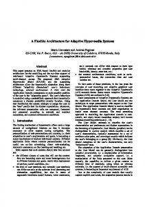
Fig. 1. The modular idea: a library of crane beam, joint and actuator models that can be used as modules to simulate different cranes or robotic arms. The arm joint angles can be calculated at runtime according to the specific kinematic model of the robot which can be selected among a set of different kinematic typologies.
this paper, the main focus is on building a flexible modeling and simulation architecture for controlling the end effector of maritime cranes. The crane cable and all problems related to rope pendulations or wave impacts on the payload are not considered in this preliminary work but they can be included in the model at a later stage. Currently, it is still quite common to use simple joysticks to control maritime crane operations. Most of the control approaches are based on the concept of tele-operation, and usually each input device can control only one specific robotic crane. When considering working efficiency and safety, this kind of control is extremely difficult to manage and extensive experience with high control skill levels is required of the operators (Nielsen 2007). Therefore, low control flexibility and non-standardisation are indeed two crucial points of the current crane control architecture that need to be overcome. To improve safety and efficiency on board, it could be useful to employ some kind of common controller that would be much more intuitive for the crane operators. Such interfaces could also provide the machinist with force feedback so that he would be able to feel the lifted loads and better manage the operations. Such types of devices are known as haptic interfaces. Haptics is a particular area of study within
and robots that operate on ship decks, a mathematical model - which also includes the vessel dynamics is needed. Such a model can be complicated in the sense that we have to deal with multi-domain systems where a large number of degrees of freedom and a large number of rigidly connected parts are involved.
the Human Machine Interface (HMI) field concerning tactile (touch) feedback through forces, vibrations, and/or motions to the user (Amerongen 2000). The use of these devices can reduce the cognitive load of the operator and make the work more efficient and safe. Since 2012, our research group started to work on designing and developing a more flexible and safe control system for maritime cranes. This work is supported by the programme for maritime activities and offshore operations (also named MAROFF) which is promoted by the Research Council of Norway. In our opinion, virtual prototyping is a crucial step during the design process and includes several benefits (Lumia et al. 1997) (de Melo & Mangili 2009). Development time can be significantly reduced. Building a proof of concept virtual prototype takes much less time than building a physical prototype. Therefore, simulations and virtual prototyping are indeed necessary steps to validate the design before committing to making a physical prototype. In this paper, the authors present a modular prototyping system architecture, shown in Figure 1, that allows for modeling, simulating and controlling different robotic arms and cranes regardless of their kinematic structure, degrees of freedom, body morphology, constraints, affordances and so on. The resulting models are simulated in a virtual environment and controlled by using the same input haptic device which provides the user for a valuable force feedback. The idea is to develop a library of rigid bodies, joints, actuators and kinematic models that can be used as modules to simulate different cranes or robotic arms. The base module of this architecture is the crane beam model. Using different joint modules to connect several such models, different crane models can be easily built. The arm joint angles can be calculated at runtime according to the specific kinematic model of the robot which can be selected among a set of different kinematic typologies. The library also includes a simplified model of a vessel to which the arm models can be connected to get a complete model. The paper is organised as follows. In Section II, justifications for the chosen modeling technique and a review of the related research work are given. In Section III, we focus on the description of the system model. In Section IV, a simplified vessel model with a crane consisting of two beams connected together is presented as an example. The related simulations and the obtained results are also shown. In Section V, conclusions and future works are outlined. II.
R ELATED R ESEARCH W ORK
Several aspects were considered in choosing a modeling technique to develop the prototyping system. •
•
Energy based approach. An important aspect in the design of this system is the interaction with human beings that have to be intrinsically safe. Robust stability is needed and such a level of stability can be obtained if controllers and controlled systems behave like physical passive systems, as stated by Hogan (Hogan 1984) with the principle of physical equivalence. This postulate motivates the energy-based approach followed in this paper. Multi-domain and complex systems. Since the idea is to develop a common haptic control system for cranes
•
Modular approach. Since the aim of this work is to control different robotic arms using the same haptic device, the mathematical model have to be flexible enough to easily modify the kinematics and dynamics of the controlled device. The modular approach used in this work is a possible way to obtain such flexibility.
•
Physical interaction. The Newton-Euler technique and Lagrange’s technique are two of the classic methods used for the modeling of the dynamics of mechatronic systems (Craig 2005). These techniques however, tend to hide the physical interaction between elements involved and do not facilitate the implementation and integration of other subsystems at a later stage.
For all these reasons, the so-called Bond Graph Method (BGM) (Karnopp et al. 2006) was chosen by the authors as a natural way to model the system. In fact, the BGM is a highly modular energy-based approach for modeling and simulation of multidomain dynamic systems. One of the biggest advantages of using the BGM is that once the BG model of the system is ready, the system state equations can be algorithmically derived from it in a systematic manner. This process is usually automated using appropriate software, which can also derive equations in symbolic form. The so-called 20-sim simulator (Amerongen 2000) was used in this work. In recent years, the benefits of the BGM have been increasingly recognised by the scientific community. In (Vaz et al. 2003), Vaz et al. discussed certain issues involved in modeling robotic manipulators using BGs and presented a new approach for symbolic derivation of Jacobian matrices. However, this algorithm is not easy to adapt to different robotic arms or cranes. Another problem that arises when modeling is that dynamic systems involving rigidly coupled inertia elements often result in derivative causality problems when represented in BG form. This means that explicit state equations can only be obtained after algebraic manipulation. In (Karnopp 1992), Karnopp presented a practical solution that consists of trying to eliminate the derivative causality by defining an I-field or an IC-field using generalised momentum and (if necessary) generalised coordinates, as is done when applying Lagrange’s or Hamilton’s equations. Later, in (Pedersen 2009), this same approach has been used by Pedersen for an efficient implementation of rotordynamic models in bond graphs. Eventually, the author, also proposed a derivation of the same concept for Marine Vehicle Dynamics (Pedersen 2012). In (Allen 1979), Allen presented a technique based on multi-dimensional BG or Vector BG which produces explicit Lagrange or Hamilton equations for dynamic mechanisms suitable for computer solutions. Using a similar approach, Filippini et al. in (Filippini et al. 2004) applied the multibody theory through the Vector BG technique with the purpose of designing a multibond graph library for such systems. This
represents one of the first attempts to build a model that can be used to model different mechatronic systems. In (Fagereng 2011), Fagereng proposed an implementation in Vector BG of the general rigid body equations of motion for a marine vehicle in 6 DOF. The main advantage of this approach is that it supports the modeling process and setup of different marine mechatronic systems. However, no force feedback was considered in the previous literature. In our work, rigid body dynamics are used in combination with vector BGs so that the model of the systems can be created in a easier way and incorporated with the vessel dynamic equations as discussed in (Fagereng 2011). Moreover, valuable force feedback is integrated in the control loop and provided to the crane operator. III.
S YSTEM ARCHITECTURE
The idea is to develop a library of rigid bodies, joints and actuators models that can be used as modules to simulate different cranes or robotic arms. The base module of this architecture is the crane beam model. Using different joint modules to connect several such models, different crane models can be easily built. The library also includes a simplified model of a vessel to which the arm models can be connected to get a complete model. In this section all the modules of the library are presented. One possible way to realise this architecture consists of combining rigid body dynamics and multi-dimensional power bonds (Pedersen 2009) (Pedersen 2012). Lagrange’s method has proven to be particularly useful for such situations and it can be included in Hamiltonian form in the BGs by way of a modified version of an I-field or by using a special type of element known as an IC-field, which is a multiport generalisation and a combination of an I element and a C element. (Karnopp et al. 2012). A. Crane beams and rigid body modeling
Fig. 2.
Rigid body bond graph.
body from the axis. Thus, the kinetic energy can be rewritten as: Z Z 1 1 ~ ×~r)(ω ~ ×~r)dV ~ T = m~ ρ(ω vO · v~O + v~O (ω × ρ~rdV ) + 2 2 1 1 > ~ × m~rc ) + ω ~ {I}ω ~, = m~ vO · v~O + v~O · (ω 2 2 (3) where ~rc is the centre of mass and {I} is the inertia tensor. Now that we have the kinetic energy, the motion equations can be written in a quasi-Lagrangian formulation as: d dT dT ~× ( )+ω = ~τv , ~ ~ dt dv dv
(4)
dT dT d dT ~× ( +~v × )+ω = τ~ω . ~ ~ ~ dt dω dω dv
(5)
Using the Lagrange formulation, the equations for the generalised momentum can be written as: ~pv =
dT , d~v
(6)
dT . (7) ~ dω Consequently, the motion equation can be rewritten in the momentum form: p~ω =
~pv dT ~× +ω = ~τv , dt d~v
(8)
In order to implement a crane beam model, which will be the base model for our modular system, the motion of a rigid body in space has to be studied. Let us consider a rigid body in space with density ρ, mass m and velocity v. Let x, y, z be a coordinate frame with origin o, fixed in the rigid body and moving with it, and let X, Y , Z be the corresponding inertial coordinate frame with origin O from where the body is generally observed. The general motion equations in 6 DOF can be found and put in matrix form as:
p~ω dT dT ~× +ω +v× = τ~ω . (9) ~ dt dω d~v Considering that the expression of the generalised momentum always assumes the same special form when the actual differentiations are carried out, the equation for the generalised momentum can be written in matrix form as:
M~v˙ +C(~v)~v = ~τ,
~p = M(~q,t)~v + a(~q,t),
(1)
~x , F ~y , ~Fz , M ~ x, M ~ y, M ~ z ]> is the external where ~τ = [F force/momentum vector, M is the mass matrix and C(~v) is the Coriolis-centrifugal matrix. In order to implement this equation in the BG the kinetic energy of the rigid body has to be considered. It can be expressed as: 1 T= 2
ZZZ
~ ×~r)> (~v + ω ~ ×~r)dV, ρ(~v + ω ]>
(2) ]>
~ = [ω ~ x, ω ~ y, ω ~ z are where, in this case, ~v = [~vx ,~vy ,~vz and ω the linear and angular velocities of the local reference frame, respectively; while ~r is the radius vector of a point within the
(10)
where M(~q,t) is a N × N symmetric matrix of elements each possibly functions of the displacement ~q and the time t, and a(~q,t) a vector of elements which only occurs if the system includes time-varying velocity sources. Solving for ~q˙ and ignoring the time-varying component gives an expression for the rate of change of the generalised displacement as: ~q˙ = M−1 (~q,t)~p.
(11)
In this way, the rigid body equation can be programmed in a modified I-field connected to only one one-junction representing the motion in 6 DOF as shown in Figure 2. The
Fig. 4. Complete rigid body bond graph of a crane beam. The TF-elements represent the beam tips where the joint modules can be connected.
Fig. 3.
Euler angle XY Z transformation.
constitutive relation for the I-field is: f = M−1~p,
(12)
e = C(~v)~v.
(13) Fig. 5.
In order to have a complete BG of the crane beam, the relation between the local coordinate frame and the global reference from which all motion is observed has to be derived. These transformations can be expressed using the Euler angles (Karnopp et al. 2006). In this paper, the so-called XY Z convention was adopted to generate the set of rotation matrices. To find the values of the Euler angles, the relation between the body-fixed rotational velocities and the rate of change of the Euler angles must be considered. Thus, the time rate of change of the Euler angles can be obtained as follows: θ˙ = cos(φ )ωy − sin(φ )ωz , ψ˙ =
sin(φ ) sin(φ ) ωy + ωz , cos(θ ) cos(θ )
φ˙ = ωx + sin(φ )tan(θ )ωy + cos(φ )tan(θ )ωz .
Spherical joint bond graph.
to have integral causality (Karnopp et al. 2006). Since it is known that the source of derivative causality in such elements is the rigid connection, a possible solution consists of realising flexible connections. An imaginary infinite spring is used to connect two rigid bodies. Whenever forces acting on the two bodies try to pull them apart, a proportional large spring force will oppose separation. Such an imaginary spring can be modelled in BGs using a 6 DOF C-element that behaves almost like a rigid connection.
(14) B. Joints (15) (16)
The resulting transformations can be implemented in modulated transformer elements, MTF-elements, one for each subtransformation as shown in Figure 3. The rotational velocities are collected and sent to a box containing the rate-of-change Euler angles. The solved rate-of-change Euler angles are then integrated to obtain the angles and sent to their respective transformation element. By connecting the whole transformation element to our I-field model we can describe motion and forces in our rigid body system. In Figure 4, all the transformations are incorporated in one sub-model called MT Fto−global . This is the base module of our system and represents a crane beam. By connecting together several of such modules, different crane models can be implemented. However, when two rigid bodies are connected rigidly, the three linear and three angular velocities cannot all be implemented, meaning that not all the I-elements are able
Joints are used to make connections between two bodies and to impose constraints on their relative movement. The spring connection is the basis for the modeling of joints (Filippini et al. 2004). Using spring elements the three basic representations of joints (spherical, revolute and prismatic) can be implemented in BGs. Spherical joints: a spherical joint allows the three main axis rotations between the joined bodies while translation is prohibited. The BG model of this element is shown in Figure 5. In this model, the PowerDemux element separates the linear and angular efforts and flows coming from the 6 DOF input power bond and sends out two power bonds: the top one represents the linear component and the bottom one represents the angular contribution. The linear velocities are then constrained with a C-element that has a sufficiently high spring constant, which means that translation is forbidden. The Se-element that is attached to the unconstrained angular velocities is a zerotorque element, which means that the effort value is set to zero, thus representing total freedom to rotate. The PowerMux element collects the angular and linear velocities and merges them into one power bond. Moreover, at each end of the model
actuator 1 T = J^T F Haptic device
!"
F actuator 2 !# ... kinematic typologies !$
Fig. 7.
actuator n
Joint actuation.
D. Control
Fig. 6.
Prismatic joint bond graph.
there is a coordinate transformation block. This element is similar to the one used when transforming between global and local coordinates but this time it is tuned to only account for the transformation of linear velocities and forces. Finally, in order to model the energy dissipation in the joint, R-elements can be added to the BG just as the Se-elements. Revolute joints: A revolute joint is similar to a spherical joint but only allows for rotation in one angular direction, meaning that the other two are constrained in addition to the translational degree of freedom. Prismatic joints: a prismatic joint allows for translation in one direction while the other two translational degrees of freedom as well as the all three rotational movements are constrained. The unconstrained power bond has a zero effort source meaning total freedom to translate as shown in Figure 6. C. Actuators The joint elements can be used to model elongation and rotation of crane beams and robots links. To control the joint movements, actuators imposing force or torques in the unconstrained directions can be used. Typical actuators are electric motors and hydraulic cylinders, as is often the case with cranes. In this work, the focus is on hydraulic actuators. Rotary actuators: When modeling hydraulic rotary actuators, the joint motion can be controlled by applying a counter torque whose centre of application is somewhere along the beam. Applying a counter torque actually requires almost no modifications to the joint BG models. In fact, the effort value can simply be applied to the joint Se-elements, which previously represented zero efforts. Linear actuators: Hydraulic linear actuator forces acting on the beam can be added in different ways. A possible approach involves using the existing Se-element that models the gravity force or adding a new Se-element to the global one-junction, thus representing a force in the positive global z direction for instance. This solution is quite close to representing the physical actuator since the torque in the global x direction will decrease as the beam is elevated.
Thanks to the modularity of the discussed architecture, several beam models can be connected using different joint models and various cranes or robotic structures can be implemented. However the control of the system is still missing. To implement the control part, instead of using simple effort sources as inputs for the actuator models, the actual actuator forces can be calculated according to the dynamic model of the arm that has to be controlled. In particular, the force that the user applies on the haptic device can be used to calculate the actual actuator efforts. To do this the principle of virtual works (Zhang & Song 1993) can be applied: ~T = J T ~F,
(17)
where ~F is the vector of the forces and torques that have to be realised, J is the Jacobian matrix of the controlled crane and ~T is the vector containing the actuator efforts. The idea is shown in Figure 7. A set of different Jacobian matrices which correspond to a set of different kinematic typologies was included in the proposed library. The parameters of each generic Jacobian matrix, such as for instance the length of the links, have to be set according to the specific crane to be controlled. E. Force feedback In order to provide the user with valuable force feedback, a BG effort sensor can be used to measure forces and torques exerted on the end effector of the controlled arm. These efforts can be scaled and sent to the haptic device that will actuate them. F. Vessel model The vessel model may take into account radiation-induced forces (added mass, hydrodynamic damping and restoring forces), environmental forces (ocean currents, wind and waves) and propulsion forces (propeller/thruster forces and control surface/rudder forces). The general motion equation can be extended to include all of these contributions: [MRB + MA ]~ν˙ + [CRB (~ν) +CA (~ν)]~ν + D(~ν)~ν + G(~η ) (18) = ~τ + τ~H , where MRB~ν˙ represents the rigid body forces and momentum, MA ν indicates the hydrodynamic added mass forces and moments, CRB (~ν)v denotes the rigid body Coriolis and centripetal forces and moments, CA (~ν) is the hydrodynamic Coriolis and centripetal forces and moments, D(~ν)~ν is the combined expression for the hydrodynamic forces and moments which
Operator 20-sim p
F
Vessel
Haptic device F
p
p
! Kinematic model
DLL F
Fig. 8.
Arm/crane
Payload
F F
Vessel bond graph.
Fig. 10. The static-link library invocation that allows for connecting the haptic device to the simulator environment.
The system was implemented by means of a BG and simulated in 20-sim (Broenink 1999). 20-sim is a modeling and simulation package that provides a large library containing all standard BG elements. Next to standard elements 20-sim supports custom user made BG models. This functionality was utilised in this work to develop the proposed library of rigid bodies, joints and actuators models that can be used as modules to simulate different cranes or robotic arms.
Fig. 9.
The two beam crane model that was implemented and tested.
may include radiation-induced potential damping, linear skin friction damping, wave drift damping and vortex shedding damping, G(~η ) is the restoring forces and moments, ~τ represents the propulsion forces and moments, τ~H represents the environmental forces and moments. As shown by Pedersen in (Pedersen 2012) and Fossen in (Fossen 1994), the vessel can be also modelled as a rigid body with the addition of a C-element representing the restoring forces and an R-element representing the hydrodynamic damping. The model is shown in Figure 8. To fully complete the vessel model, an effort source is connected to the onejunction for the earth-fixed coordinate system representing gravity. There is also another effort source connected to the local one-junction, which can be used to simulate local forces on the vessel. Finally there is a port that can be used to attach some equipment to the model - it will be used to attach the crane. IV.
S IMULATIONS AND E XPERIMENTAL R ESULTS
In order to validate efficiency and flexibility of the proposed system architecture, a two beam crane model connected to a simplified vessel model was implemented and tested as shown in Figure 9 . In this preliminary study, a commercial haptic device, the omega.7 from Force Dimension, was used as universal input for the system. The omega.7 is a 7 DOF haptic interface with high precision active grasping capabilities and orientation sensing. Finely tuned to display perfect gravity compensation, its force-feedback gripper offers extraordinary haptic capabilities, enabling instinctive interaction with complex haptic applications. Thanks to the modularity of the proposed system, the same input device can be also used to control several different models.
A static-link DLL library was implemented in order to connect the omega.7 haptic device to the simulator environment as shown in Figure 10. At each simulation time-step the static dll sub-model calls a specific function to read the position of the input device’s end effector and to write down the efforts that are used to give force feedback to the operator. In order to simulate the vessel model, the added mass matrix and the Coriolis matrices were simplified because, in practice, deriving all of their coefficients can be an extensive process. The simplified version of the added mass matrix only has diagonal terms and the coefficients are simplified to only one parameter. These simplifications can be justified by the fact that the off diagonal terms in the added mass matrix tend to be much smaller the diagonal, having less impact on the model behavior. These approximations are actually valid assuming small velocities and that the vehicle has three planes of symmetry (Fossen 1994). The simplified versions of the matrices are MA = −diag{X~u˙ ,Y~v˙ , Z~w˙ , K~p˙ , M~q˙ , N~r˙ }, 0 0 0 CA (~ν) = 0 Z ˙ ~w ~w −Y~v˙~v
0 0 0 −Z~w˙ ~w 0 X~u˙~u
0 0 0 Y~v˙~v −X~u˙~u 0
0 Z~w˙ ~w −Y~v˙~v 0 N~r˙~r −M~q˙~q
(19)
−Z~w˙ ~w Y~v˙~v 0 −X~u˙~u X~u˙~u 0 , −N~r˙~r M~q˙~q 0 −K~p˙~p K~p˙~p 0 (20)
The complete model of the crane connected to the vessel was simulated and tested. The plot in Figure 11 shows the motion of the crane end-effector along the z axis as a result of the haptic input device’s movements which is operated by the user. In this particular case, the operator manoeuvres the crane model to lift the end effector up at first, then down and up again. Similar results were obtained for the x axis showing that the system is quite responsive to the user’s inputs. The operator also perceives a force feedback that is proportional to the end effector’s elevation as shown in Figure 12.
Another issue that has to be better investigated in the next future concerns the effectiveness of using such a haptic device on board of a vessel from a human factor point of view. In the future, the proposed system architecture could be used for finding dynamic responses in complex marine operations or for controlling a real crane on a vessel. However, for such applications, the level of accuracy in the model must be raised and a more accurate tuning of all the involved parameters has to be carried out. Fig. 11. Motion of the crane end-effector (in m) along the z axis as a result of the haptic input device’s movements which is operated by the user.
Fig. 12.
Force feedback (in Newton) perceived by the crane operator.
All the simulations were performed using damping elements in the joints in order to reduce high frequencies and thus shorten the simulation time. The damping parameters were set to values that ensured that the system would be critically damped in all our simulations. V.
C ONCLUSION AND F UTURE W ORK
In this paper, the so-called Bond Graph Method was used to introduce a modular system architecture that allows for modeling and simulating different maritime cranes or robotic arms. The base module of this architecture is the crane beam model. Using different joint modules to connect several such models, different crane models can be easily built. The resulting models can be simulated and controlled by using the same input haptic device which provides the user for a valuable force feedback. The arm joint angles are calculated at runtime according to the specific dynamic model of the robot to be controlled. Using the proposed approach, each arm model can be connected to a simplified model of a vessel, providing a complete model. Related simulations were carried out to validate the efficiency and flexibility of the proposed architecture. In this preliminary study, the results show a general trend and a qualitative idea of the system behaviour. However the proposed approach can be used to get more accurate results using proper parameter tuning and deriving a more realistic set of coefficients according to the specific case of study. As future work, it will be useful to model, simulate and compare different crane configurations to prove the flexibility of the proposed architecture. A comparison with traditional modeling methods will also be necessary to prove the advantage of using Bond Graphs over other modeling techniques.
R EFERENCES Allen, R. (1979), ‘Multiport representation of inertia properties of kinematic mechanisms’, Journal of the Franklin Institute 308(3), 235–253. Amerongen, J. (2000), Modeling, simulation and controller design for mechatronic systems with 20-sim 3.0, in ‘1st IFAC conference on Mechatronic Systems, Darmstadt, Germany’. Broenink, J. (1999), ‘20-sim software for hierarchical bondgraph/block-diagram models’, Simulation Practice and Theory 7(5), 481–492. Craig, J. J. (2005), Introduction to robotics: mechanics and control, Pearson/Prentice Hall Upper Saddle River, NJ, USA:. de Melo, L. & Mangili, J. (2009), Virtual simulator with mobile robot rapid prototyping for navigation systems, in ‘ICIA International Conference on Information and Automation’, IEEE, pp. 899–904. Fagereng, C. (2011), Mathematical Modeling for Marine Crane Operations, PhD thesis, Norwegian University of Science and Technology. Filippini, G., Delarmelina, D., Pagano, J., Alianak, J., Junco, S. & Nigro, N. (2004), ‘Dynamics of multibody systems with bond graphs’, Mec´anica Computacional 26, 2943–2958. Fossen, T. (1994), ‘Guidance and control of ocean vehicles’, New York . Hellrand, A., Moen, L. & Faanes, T. (1990), Crane control system with active heave compensation and constant tension modes onboard the vessel stena wel/servicer, in ‘Offshore Technology Conference’. Hogan, N. (1984), Impedance control: An approach to manipulation, in ‘American Control Conference’, IEEE, pp. 304– 313. Johnson, P. R. (1985), ‘Offshore crane wave motion compensation apparatus’. US Patent 4,544,137. Karnopp, D. (1992), ‘An approach to derivative causality in bond graph models of mechanical systems’, Journal of the Franklin Institute 329(1), 65–75. Karnopp, D., Margolis, D. & Rosenberg, R. (2006), System dynamics: modeling and simulation of mechatronic systems, Vol. 3, John Wiley & Sons New Jersey. Karnopp, D., Margolis, D. & Rosenberg, R. (2012), System Dynamics: Modeling, Simulation, and Control of Mechatronic Systems, Wiley. Lumia, R., Starr, G., Wood, J., Jones, B., Shohet, I. & Ledman, E. (1997), An approach to minimize robotics system development and integration time, in ‘Proceedings., International Conference on Robotics and Automation’, Vol. 4, IEEE, pp. 3220–3225. McKenna, P. & Leithead, W. (2007), Semi-autonomous control of offshore cranes, in ‘Institution of Engineering and Technology Conference on Autonomous Systems’, IET, pp. 1–6.
Nielsen, F. (2007), ‘Lecture notes in marine operations’, Department of Marine Structures, Norwegian University of Science and Technology, Trondheim, Norway . Pedersen, E. (2009), Rotordynamics and bond graphs: basic models, in ‘Journal of Mathematical and Computer Modeling of Dynamical Systems’, Vol. 15, No.4, pp. 337–352. Pedersen, E. (2012), Bond graph modeling of marine vehicle dynamics, in ‘Bond Graph Modeling: Theory and Practice Symposium at the 7th Vienna International Conference on Mathematical Modeling’. Vaz, A., Kansal, H. & Singla, A. (2003), Some aspects in the bond graph modeling of robotic manipulators: angular velocities from symbolic manipulation of rotation matrices, in ‘TENCON Conference on Convergent Technologies for Asia-Pacific Region’, Vol. 1, IEEE, pp. 294–299. Yi, J., Yubazaki, N. & Hirota, K. (2003), ‘Anti-swing and positioning control of overhead traveling crane’, Information Sciences 155(1), 19–42. Zhang, C. & Song, S. (1993), ‘An efficient method for inverse dynamics of manipulators based on the virtual work principle’, Journal of Robotic Systems 10(5), 605–627. AUTHOR BIOGRAPHIES FILIPPO SANFILIPPO is a PhD candidate in Engineering Cybernetics at the Norwegian University of Science and Technology, and research assistant at the faculty of Maritime Technology and Operation, Aalesund University College, Norway. He obtained his Masters Degree in Computer Engineering at University of Siena, Italy. Email:
[email protected] HANS PETTER HILDRE is a Professor on Product and System Design at the Department of Maritime Technology and Operation, Aalesund University College, Norway. Email:
[email protected]. VILMAR ÆSØY received his PhD in Mechanical Engineering in 1996 at the Norwegian University of Science and Technology, Department of Marine Technology. From 1997-2002 he worked in the maritime industry as researcher in Aker Maritime and R&D manager in Rolls-Royce Marine. Since 2002 as Assistant Professor in Mechanical and Marine Systems Engineer at Aalesund University College, Department of Maritime Technology and Operation. Email:
[email protected]. HOUXIANG ZHANG received Ph.D. degree in Mechanical and Electronic Engineering in 2003. From 2004, he worked as Postdoctoral Fellow at the Institute of Technical Aspects of Multimodal Systems (TAMS), Department of Informatics, Faculty of Mathematics, Informatics and Natural Sciences, University of Hamburg, Germany. Dr. Zhang joined the Department of Maritime Technology and Operation, Aalesund University College, Norway in April 2011 where he is a Professor on Robotics and Cybernetics. Email:
[email protected]. EILIF PEDERSEN is a Associate Professor on Modeling and simulation of machinery systems at the Department of Marine Technology, Norwegian University of Science and
Technology, Norway. Email:
[email protected].