In the present study the hydrodynamic interaction of regular and irregular waves
with floating breakwaters (FBs) in shallow and intermediate waters is examined ...
Journal of Hydraulic Research Vol. 43, No. 2 (2005), pp. 174–188 © 2005 International Association of Hydraulic Engineering and Research
Floating breakwaters under regular and irregular wave forcing: reflection and transmission characteristics Brise-lames flottants soumis à une houle régulière et irrégulière forcée: caractéristiques de réflexion et de transmission E. KOUTANDOS, Hydraulics Laboratory, Department of Civil Engineering, Aristotle University of Thessaloniki, 54124 Thessaloniki, Greece. Fax: 2310995672; e-mail:
[email protected] (author for correspondence) P. PRINOS, Hydraulics Laboratory, Department of Civil Engineering, Aristotle University of Thessaloniki, 54124 Thessaloniki, Greece. E-mail:
[email protected] X. GIRONELLA, Laboratori d’ Enginyeria Maritima, Catalonia University of Technology, LIM-UPC, D1 ETSECCPB, c/Gran Capitan s/n, 08034, Barcelona, Spain. E-mail:
[email protected] ABSTRACT In the present study the hydrodynamic interaction of regular and irregular waves with floating breakwaters (FBs) in shallow and intermediate waters is examined experimentally in a large-scale facility. The experiments were conducted in the CIEM flume of the Catalonia University of Technology, Barcelona. The influence of incident wave characteristics and certain geometric characteristics, such as the width and the draught of the structure, on its efficiency is examined. Four different FBs configurations are examined: (a) single fixed FB, (b) heave motion FB, (c) single fixed FB with attached front plate (impermeable and permeable) and (d) double fixed FB. Results related to transmission, reflection, and energy dissipation of the incident (regular and irregular) waves on the structure are presented. For the single fixed FB, the efficiency of the structure is proportional to the width/wavelength and draught/water depth ratios. The single fixed FB operates in a highly reflective manner. On the other hand, the heave motion FB operates in a dissipative manner with much lower reflection. The attached plate in the front part of the FB significantly enhances the efficiency of the structure. No significant differences are observed between the impermeable and the permeable plate cases. Generally, the most efficient configuration has been the double fixed FB. However, with regard to cost-effectiveness, the configuration of the FB with the attached plate should be considered the most efficient for design purposes. RÉSUMÉ Dans la présente étude l’interaction hydrodynamique des vagues régulières et irrégulières avec des brise-lames flottants (FBs) en eaux peu profondes et intermédiaires est examinée expérimentalement dans une installation à grande échelle. Les expériences ont été menées dans le canal de CIEM de l’université de technologie de Catalogne, Barcelone. Leur efficacité est examinée en fonction des caractéristiques des vagues incidentes et de certaines caractéristiques géométriques, telles que la largeur et le tirant d’eau de la structure. Quatre configurations différentes de FBs sont examinées: (a) FB simple fixe, (b) FB en pilonnement, (c) FB simple fixe avec une plaque attachée sur l’avant (imperméable et perméable) et (d) FB double et fixe. On présente les résultats liés à la transmission, à la réflexion, et à la dissipation d’énergie de des vagues incidentes (régulières et irrégulières) par la structure. Pour le FB simple fixe, l’efficacité de la structure est proportionnelle aux rapports de largeur/longueur d’onde et tirant d’eau/profondeur d’eau. Le FB fixe simple est fortement réfléchissant. D’autre part, le FB avec mouvement de pilonnement est dissipatif avec un réflexion bien inférieure. La plaque attachée dans la partie avant du FB augmente de manière significative l’efficacité de la structure. On n’observe pas de différences significatives entre les plaques imperméables et perméables. Généralement, la configuration la plus efficace a été FB double et fixe. Cependant, en ce qui concerne la rentabilité, la configuration du FB avec la plaque avant devrait être considéré comme le plus efficace pour les projets.
Keywords: Floating breakwater, transmission, reflection, energy dissipation. 1 Indroduction
The main function of an FB is to attenuate wave action. Such a structure cannot stop all the wave action. The incident wave is partially transmitted, partially reflected, and partially dissipated. Energy is dissipated due to damping, friction and the generation of eddies at the edges of the breakwater. The breakwater generates a radiated wave which is propagated in offshore and onshore
In the last decade, environmentally friendly coastal structures have become of great interest. Floating breakwaters (FBs) belong to this specific category for wave protection and restoration of semi-protected coastal regions.
Revision received October 14, 2004 / Open for discussion until November 30, 2005.
174
FBs under regular and irregular waves
directions. The movement of the breakwater is specified in terms of the anchoring, which defines the degrees of freedom of the breakwater. The hydrodynamic problem of FBs is extremely complex especially in the case of a moving structure. There are several studies dealing with the hydrodynamic problem of FBs in deep and intermediate water depth. Linear models and analytical solutions, which describe the full hydrodynamic problem, have been developed by Hwang and Tang (1986), Williams and McDougal (1991), Drimer et al. (1992), Bhatta and Rahman (1993), Isaacson and Bhat (1998), Williams et al. (2000) and Kriezi et al. (2001). A coupled solution for diffraction and body movement is proposed to eliminate the error introduced by the linear approach of the problem (Isaacson, 1982a; Gottlieb and Yim, 1995). A limited number of studies have dealt with the interaction of the floating body with oblique waves (Isaacson and Bhat, 1998; Sannasiraj et al., 1998). The current behind the floating structure has also been studied (Isaacson and Cheung, 1993), while overtopping has been studied by Isaacson (1982b). Different models have been studied which calculate the forces on the mooring system of an FB (Niwinski et al., 1982; Yamamoto, 1982; Yamamoto et al., 1982; Nossen et al., 1991; Yeung et al., 1992; Isaacson and Bhat, 1994; Yoon et al., 1994). However, the experimental studies are rather limited, performed in small-scale facilities, and only for regular wave forcing. Sutko and Haden (1974) presented a series of small-scale experiments. Fugazza and Natale (1988) studied the phenomenon numerically and experimentally. They investigated the influence of the stiffness of the horizontal part of the mooring system. An experimental study of the phenomenon for a breakwater in a floating mode was presented by Williams (1988), in which the efficiency and the response of the structure was studied. Tolba
175
(1998) and Isaacson and Bhat (1998) studied experimentally pile-restrained FBs and, in particular, the influence of the heave motion on the efficiency of the structure. Christian (2000) studied a 1 : 15 scale, prefabricated form of FBs, and investigated the efficiency of the structure and the horizontal forces acting on it in a laboratory model. In this study the hydrodynamic interaction of regular and irregular waves with FBs in shallow and intermediate waters is examined experimentally in a large-scale facility. The influence of the incident wave characteristics and certain geometric characteristics, such as the width and the draught of the structure, on its efficiency is examined for four different FBs configurations: (a) single fixed FB, (b) heave motion FB, (c) single fixed FB with attached front (permeable and impermeable) plate and (d) double fixed FB.
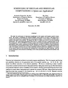
2 Experimental facility and procedure The experiments were conducted in the CIEM flume of the Catalonia University of Technology, Barcelona. The dimensions of the flume are 100 m length, 5 m depth and 3 m width. The FB was placed in the horizontal part of the flume in 2 m water depth. The length B of the breakwater was 2 m, the height 1.5 m and the transverse length 2.8 m. An HR Wallingford wedgetype, wave maker was used, while the experimental equipment consisted of a number of Wallingford wave gauges, Huba Control pressure transducers, and two-component Delft Hydraulics current meters. In Fig. 1, the layout of the flume and the instrumentation are shown for the single breakwater test, while the double breakwater case is presented in Fig. 2. During the experiments, a moving carriage was used for the wave gauges for
FB WG CRM PS
WAVE-GAUGE CURRENT-METER PRESSURE-SENSOR
PS2 PS3
PS4 PS5
PS7 PS6 5720 cm 4700 cm
WG5 WG2
312 cm
WG0
WG3
WG4
CRM0 CRM1 PS0
PS1
FB
WG6
WG7
PS8
PS9
500 cm
WAVE-MAKER
CRM2
5873,5 cm 8725 cm 9658 cm
Figure 1 Layout of the CIEM flume with the single fixed FB and the instrumentation.
FB1 WG CRM PS
WAVE-GAUGE CURRENT-METER PRESSURE-SENSOR
PS2 PS3
PS4 PS5
PS7 PS6 5720 cm
950 cm
WG5 312 cm
WG0
WG2
WG3
WG4
CRM0 CRM1 PS0
PS1
FB1
475 cm
WG6
4700 cm
FB2
WG7 500 cm
WAVE-MAKER
CRM2 PS8
PS9
5873,5 cm 8725 cm 9658 cm
Figure 2 Layout of the CIEM flume with the double fixed FB and the instrumentation.
176
Koutandos et al.
calculating reflection to maintain the appropriate distances proposed by Mansard and Funke (1980) between the three wave gauges and a distance greater than at least a half wavelength between the carriage and the structure. Wave gauges in the lee of the structure, used for the estimation of transmission, were also placed at different locations during the experiments to maintain at least half a wavelength from the structure and half wavelength between them. The sampling frequency during the experiments was 20 Hz. The experiments were organized into four different sets, according to the configuration of the FB. Four different FB configurations were examined: (a) single fixed FB, (b) heave motion FB, (c) single fixed FB with attached front (permeable and impermeable) plate and (d) double fixed FB. In every set, regular and irregular waves were generated covering a range of shallow and intermediate waters (0.04 < d/L < 0.35, d = waterdepth, L = wavelength). The four configurations are presented in Figs 3–6, respectively. For the single, fixed FB three different draughts (dr) were used 0.4 m, 0.5 m and 0.65 m (dr/d = 1/5, 1/4 and 1/3, respectively). For the regular waves case two different wave heights were used,
0.2 and 0.3 m. The shortest wave period was 2.04 s (B/L = 0.32) for the 0.2 m height and 2.34 s for the 0.3 m height. For the 0.3 m wave height shorter periods were avoided because violent wave breaking on the structure occurred. In both cases, the longest wave period was 9.17 s (B/L = 0.0445). The irregular waves were generated according to JONSWAP spectrum, with a shape parameter γ equal to 3.3. The significant wave height was 0.3 m. Three peak wave periods were used for every draught 2.67 s (B/L = 0.19), 3.16 s (B/L = 0.15) and 5.04 s (B/L = 0.08). It should be noted that B/L is equal to d/L (B = d in the experiments). Approximately 1200 waves were generated to obtain the appropriate statistical information for the reconstruction of the energy spectrum. In the second set of experiments, a heave motion FB was tested. The initial draught of the FB was 0.4 m (dr/d = 1/5). Iron rails were attached to the walls of the flume to restrain horizontal and rotational motion of the structure, while greased pneumatic wheels were attached on the structure to allow unrestrained vertical motion with minimum friction (Fig. 4). The weight of the structure was 2240 kg while the centre of mass was 0.2 m below the free surface due to the extra uniform weight put inside the
Figure 3 The single fixed FB under wave forcing.
Figure 5 The fixed FB with the attached porous plate.
Figure 4 The heave motion FB under wave forcing.
Figure 6 The double fixed FB under wave forcing.
FBs under regular and irregular waves
breakwater. A position sensor was placed on the structure to record the vertical motion of the floating breakwater. The tested wave conditions were the same as in the single fixed FB case. In the third set of experiments, a single fixed FB with an attached metal plate at the front part was tested. Christian (2000) and Tolba (1998) experimentally tested FB with an attached metal plate at the middle of the submerged structure bottom. They concluded that the plate improves the efficiency of the structure, but not as much as in the case of FB with overall draught equal to that of the metal plate. The observed vortex generation in the front submerged part for the single fixed breakwater case (Fig. 7) lead to the idea to test the FB with the plate at the front part to reveal the impact of the position of the plate on the FB efficiency. The draught of the FB was 0.2 m (dr/d = 1/10). The height of the iron plate was 0.2 m, leading to a local draught of 0.4 m at the front face of the FB. The tested wave conditions were the same as in the single fixed FB case. Also, a single fixed FB with an attached permeable plate (with a porosity of 0.62) at the front part was tested for improving the dissipative characteristics of the plate. The geometric characteristics were the same as the impermeable plate case. Fifty holes were drilled onto the plate. Each hole had a radius of 4.3 cm, while they were equally spaced in two rows in the plate, resulting in a porosity of 0.62 (Fig. 5). The tested wave conditions were the same as in the single fixed FB case. In the fourth set of experiments, a double fixed FB was tested. The geometric characteristics of the two breakwaters were the same. In Fig. 2, the layout of the flume with the double breakwater is presented. The distance between the two breakwaters was 9.5 m and their draught was 0.5 m. In Fig. 6, a photograph from the specific set of experiments is presented. The tested wave conditions were the same as the single fixed FB case. Wave reflection and transmission were estimated for every case. The wave reflection analysis is based on the method
Figure 7 Vortex generation in the upstream bottom part of the fixed FB.
177
proposed by Mansard and Funke (1980). The method is employed using the signals from wave gauges 3, 4 and 5. Energy dissipation in the region of the breakwaters is also studied using the following equation: Ct2 + Cr2 + Cd2 = 1
(1)
where Ct is the transmission coefficient (Ht /Hi ), Cr the reflection coefficient (Hr /Hi ), Cd the energy dissipation coefficient, Ht the height of the transmitted wave, Hr the height of the reflected wave, and Hi the height of the incident wave.
3 Dimensional analysis The efficiency of the FB is expressed through the abovementioned transmission coefficient Ct . Christian (2000) presented the following equation as a result of dimensional analysis of the phenomenon for an elastically moored FB: Ct = f(Hi /L, B/L, dr/d, d/Hi , M/γb Bdr, I/MB2 , DG /dr, kB/Mg)
(2)
where γb = specific weight of the breakwater, g = sea water specific weight, M = mass of the breakwater, I = second moment of inertia, DG = centre of gravity of the breakwater from underside and k = stiffness of the mooring system. The ratios of B/L and dr/d for both regular and irregular waves in the case of the single fixed FB have been shown to be the most important parameters. For the heave motion FB, the influence of the motion on the efficiency is examined (Fig. 8). The influence of a plate and porous plate, offering an increased local draught, is examined in the next two sets of experiments. In the last set, a double FB configuration is tested, to reveal the structural efficiency and impact of any resonance phenomena concerning the water mass between the two structures.
Figure 8 Vortex generation in the upstream bottom part of the heave motion FB.
178
Koutandos et al. 1
1 Hi=0.3 m
0.9
0.9
0.8
0.8
0.7
0.7
0.6
0.6
0.5
Cr
Cr
Hi=0.2 m
0.4
0.5 0.4
dr/d=1/3 dr/d=1/4 dr/d=1/5
0.3 0.2
0.3 0.2
0.1
0.1
0
0 0
0.05
0.1
0.15
0.2
0.25
0.3
0.35
0
B/L
0.15
0.2
0.25
0.3
0.35
0.25
0.3
0.35
0.25
0.3
0.35
1
Hi=0.2 m
Hi=0.3 m
0.9
0.9
0.8
0.8
0.7
0.7
0.6
0.6
0.5
Ct
Ct
0.1
B/L
1
0.4
0.5 0.4
0.3
0.3
0.2
0.2
0.1
0.1
0
0 0
0.05
0.1
0.15
0.2
0.25
0.3
0.35
0
B/L
0.05
0.1
0.15
0.2
B/L
1
1
Hi=0.2 m
Hi=0.3 m
0.9
0.9
0.8
0.8
0.7
0.7
0.6
0.6
Cd
Cd
0.05
0.5
0.5
0.4
0.4
0.3
0.3
0.2
0.2
0.1
0.1
0
0 0
0.05
0.1
0.15
0.2
0.25
0.3
0.35
B/L
0
0.05
0.1
0.15
0.2
B/L
Figure 9 Variation of Cr , Ct , and Cd with B/L for the single fixed FB, regular waves.
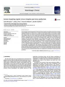
4 Analysis of the results 4.1 Single fixed FB The results for this case are presented in Fig. 9 for regular waves. The influence of B/L (or d/L since B = d in the experiments)
on the performance of the FB is shown. For B/L greater than 0.25 the performance of the structure can be considered satisfactory for all dr/d considered since Ct is less than 0.5. The FB performs more efficiently under the forcing of waves with short periods for intermediate and deep waters (d/L > 0.25).
FBs under regular and irregular waves Fixed FB (irregular waves) dr/d=1/3
4.2 Heave motion FB For this configuration the results for regular waves are presented in Fig. 11 together with the ones for the single fixed FB case for comparison purposes. In Fig. 11 the effect of B/L (d/L) on the performance of the FB is presented. For B/L greater than 0.275, the performance of the heave motion FB can be considered satisfactory since Ct is less than 0.5. The heave motion FB also performs efficiently under the forcing of short period waves in intermediate and deep waters (d/L > 0.275). The transmission coefficient reaches the values of 0.41 and 0.46 for the 0.2 and 0.3 m wave height, respectively. The energy dissipation coefficient increases with decreasing wave period, revealing the increase of energy dissipation in short period waves. Again this is due to the increasing vortex intensity, observed in the front submerged part of the breakwater, with decreasing wavelength (Fig. 8). The Cd reaches values
dr/d=1/4
dr/d=1/5
1 0.9 0.8 0.7
Cr
0.6 0.5 0.4 0.3 0.2 0.1 0 0
0.05
0.1
0.15
0.2
0.25
0.15
0.2
0.25
0.15
0.2
0.25
B/L 1 0.9 0.8 0.7
Ct
0.6 0.5 0.4 0.3 0.2 0.1 0 0
0.05
0.1
B/L 1 0.9 0.8 0.7 0.6
Cd
The effect of dr/d is also shown in this figure. Between the first two draughts (dr/d = 1/5 and dr/d = 1/4) there is no noticeable difference. In the first case (Hi = 0.2 m) the transmission coefficient reaches the value of 0.39, while in the second 0.35. The difference in transmission is obvious in the third case (dr/d = 1/3) where it reaches a value of 0.25. The variation of Cd with B/L is also shown in Fig. 9. In the first case (dr/d = 1/5), the energy dissipation coefficient increases with a decrease of wave period indicating an increase of energy dissipation for short period waves. This phenomenon is mainly observed due to the increasing intensity of oscillating air–water vortices observed in the front submerged part of the breakwater, with decreasing wave length (Fig. 7). This indicates that numerical models should correctly account for the strong vortices occurring in the front part of structure rather than those behind the structure (Kriezi et al., 2001). The latter vortices were not observed in the experiments indicating their very limited strength. For the longest period and Hi = 0.3 m, Cd reaches a value of 0.2 while for the shortest period a value of 0.4. In the second case (dr/d = 1/4), the coefficient tends to become constant with an increasing trend from 0.3 to 0.4. Finally, for the third draught (dr/d = 1/3), the energy dissipation coefficient is almost constant around a mean value of 0.45. This is due to the steadiness of the vortices in the region of the FB and the fact that an FB with deeper draught performs more efficiently in a reflective manner. The reflection coefficient in all cases is high with values of 0.4 for the longest wave period and up to 0.9 for the shortest wave period. This indicates that a fixed FB performs in a rather reflective manner, especially with deeper draught. For irregular waves, Fig. 10 shows that the trend in the transmission and reflection coefficients is similar with that of the regular wave experiments for the corresponding values of B/L and dr/d. However, there is a remarkable difference in the energy dissipation coefficient. The coefficient presents an increasing trend reaching a value of 0.65, while in the corresponding case for regular waves, the value is less than 0.5. This phenomenon reveals the influence of chaotic processes occurring during the propagation, reflection, and transmission of irregular waves.
179
0.5 0.4 0.3 0.2 0.1 0 0
0.05
0.1
B/L Figure 10 Variation of Cr , Ct and Cd with B/L for the single fixed FB, irregular waves.
of 0.45–0.5 and 0.85–0.90 for the longest and shortest period, respectively. This is mainly due to the fact that for shorter period waves, the FB moves vertically out of phase with the standing wave formed in front of the structure, while in longer period
180
Koutandos et al. Heave motion FB Fixed FB 1
1 Hi=0.3 m
0.9
0.9
0.8
0.8
0.7
0.7
0.6
0.6
Cr
Cr
Hi=0.2 m
0.5
0.5
0.4
0.4
0.3
0.3
0.2
0.2
0.1
0.1
0
0 0
0.05
0.1
0.15
0.2
0.25
0.3
0.35
0
0.05
0.1
0.15
B/L 1 0.9
0.9
0.8
0.8
0.7
0.7
0.6
0.6
Ct
Ct
0.25
0.3
0.35
0.25
0.3
0.35
0.25
0.3
0.35
1 Hi=0.2 m
0.5
Hi=0.3 m
0.5
0.4
0.4
0.3
0.3
0.2
0.2
0.1
0.1
0
0 0
0.05
0.1
0.15
0.2
0.25
0.3
0.35
0
0.05
0.1
0.15
B/L
0.2
B/L
1
1 Hi=0.2 m
0.9
Hi=0.3 m 0.9
0.8
0.8
0.7
0.7
0.6
0.6
Cd
Cd
0.2
B/L
0.5
0.5
0.4
0.4
0.3
0.3
0.2
0.2
0.1
0.1
0
0 0
0.05
0.1
0.15
0.2
0.25
0.3
0.35
0
0.05
0.1
0.15
B/L
0.2
B/L
Figure 11 Effect of heave on Cr , Ct , and Cd for regular waves.
waves the structure moves in phase with the standing wave. The out of phase vertical motion of the structure creates stronger vortices and therefore more energy dissipation. This difference in the phase angle between the vertical motion of the FB and the
standing wave formed in front of the structure was observed by Tolba (1998) using video analysis. The reflection coefficient in all cases is less than 0.3 mainly due to the high energy dissipation. The high energy dissipation and low reflection for
FBs under regular and irregular waves Heave motion FB (dr/d=1/5, irregular waves) Fixed FB (dr/d=1/5, irregular waves) 1 0.9 0.8 0.7 0.6
Cr
the heave motion FB indicates that it performs in a dissipative manner. The comparison of the fixed and the heave motion FB reveals a very basic difference in the structure hydrodynamics. The heave motion FB performs in a dissipative manner, contrary to the fixed breakwater which performs in a reflective manner. Although the transmission coefficient is almost the same for both configurations, with the fixed breakwater showing a slightly better performance, the reflection and dissipation coefficients present totally different trends due to the high energy dissipation in the case of the heave motion FB. Similar conclusions can be derived from Fig. 12 for irregular waves. The trend in the transmission coefficient is the same. There is a remarkable difference though in reflection and energy dissipation. The increased energy dissipation in the case of the heave motion FB leads to decreased reflection. Comparing values of Cd for regular and irregular waves in the case of the heave motion FB (Figs 11 and 12), energy dissipation is higher for irregular waves and B/L less than 0.1 with a value of the corresponding coefficient approximately equal to 0.7.
181
0.5 0.4 0.3 0.2 0.1 0 0
0.05
0.1
0.15
0.2
0.25
0.15
0.2
0.25
0.15
0.2
0.25
B/L 1 0.9 0.8 0.7
4.3 Fixed FB with attached (permeable or impermeable) front plate Ct
0.5 0.4 0.3 0.2 0.1 0 0
0.05
0.1
B/L 1 0.9 0.8 0.7 0.6
Cd
The experimental results for fixed FB with attached front plate for both regular and irregular waves are presented in Figs 13–15. In Fig. 13, experimental results of Ct , Cr and Cd for the FB with the attached impermeable plate are compared with the ones for the corresponding single fixed FB with the same overall draught (dr/d = 1/4). The FB with the attached front plate performs as efficiently as the single fixed FB with the same overall draught. Similar conclusions can be derived for irregular waves (Fig. 15, left column). This configuration, the FB with the attached front plate, achieves more efficient hydrodynamic performance than that examined by Tolba (1998) and Christian (2000) with an attached plate in the middle part of the structure keel. This is due to the fact that generation of energy and turbulent eddies occur in the front part of the structure, and hence a mechanism, like an attached plate for dissipating energy in this region, is more effective than a similar mechanism in another part of the structure (middle or end region). Furthermore, the proposed configuration provides more dissipation since reflection is lower and dissipation higher. This is mainly due to the increased local turbulence developed behind the plate as confirmed by video analysis performed by the authors. The results of an attempt to increase energy dissipation by making the plate permeable are presented in Fig. 14. The comparison of the results for the impermeable and permeable plates, reveals that the efficiency of the structure is not enhanced and the local turbulence is not intensified by the porosity. On the contrary, although the transmission is almost the same, energy dissipation is lower in the case of the porous plate revealing that the rather big voids in the attached plate and its small thickness contribute positively to the transmission of wave energy. However, it is believed that the structure will operate more efficiently in the case of a permeable plate if the porosity is reduced and the length is increased.
0.6
0.5 0.4 0.3 0.2 0.1 0 0
0.05
0.1
B/L Figure 12 Effect of heave on Cr , Ct , and Cd for irregular waves.
The last two parameters contribute significantly in the dissipation of energy and will be considered systematically in a subsequent study. For irregular waves, however (Fig. 15), the energy dissipation for the porous plate case is shown to be higher than that
Koutandos et al. 1
1
Hi=0.2 m
Hi=0.3 m
0.9
0.9
0.8
0.8
0.7
0.7 0.6
0.5
Cr
Cr
0.6
0.4
0.5 0.4
dr/d=1/4 plate
0.3
0.2
0.1
0.1
0
0 0
0.05
0.1
0.15
0.2
0.25
0.3
0.35
0
B/L 1
0.05
0.1
0.15
0.2
0.25
0.3
0.35
0.25
0.3
0.35
0.25
0.3
0.35
B/L 1
Hi=0.2 m
Hi=0.3 m
0.9
0.9
0.8
0.8
0.7
0.7
0.6
0.6
Ct
Ct
dr/d=1/4 plate
0.3
0.2
0.5
0.5
0.4
0.4
0.3
0.3
0.2
0.2
0.1
0.1
0
0 0
0.05
0.1
0.15
0.2
0.25
0.3
0.35
0
B/L
0.05
0.1
0.15
0.2
B/L
1
1
Hi=0.2 m
Hi=0.3 m
0.9
0.9
0.8
0.8
0.7
0.7
0.6
0.6
0.5
Cd
Cd
182
0.4
0.5 0.4
0.3
0.3
0.2
0.2
0.1
0.1
0
0 0
0.05
0.1
0.15
0.2
B/L
0.25
0.3
0.35
0
0.05
0.1
0.15
0.2
B/L
Figure 13 Effect of attached impermeable plate on Cr , Ct , and Cd for regular waves.
FBs under regular and irregular waves 1
1
Hi=0.2 m
Hi=0.3 m
0.9
0.9
0.8
0.8
0.7
0.7 0.6
0.5
Cr
Cr
0.6
0.4
0.5 0.4
0.3
plate porous plate
0.2
0.3
0.1
0
0 0
0.05
0.1
0.15
0.2
0.25
0.3
0.35
0
B/L
0.05
0.1
0.15
0.2
0.25
0.3
0.35
0.25
0.3
0.35
0.25
0.3
0.35
B/L
1
1
Hi=0.2 m 0.9
0.9
0.8
0.8
0.7
0.7
0.6
0.6
Ct
Ct
plate porous plate
0.2
0.1
0.5
Hi=0.3 m
0.5
0.4
0.4
0.3
0.3
0.2
0.2
0.1
0.1
0
0 0
0.05
0.1
0.15
0.2
0.25
0.3
0.35
0
B/L 1
0.05
0.1
0.15
0.2
B/L 1
Hi=0.2 m
Hi=0.3 m
0.9
0.9
0.8
0.8
0.7
0.7
0.6
0.6
0.5
Cd
Cd
183
0.4
0.5 0.4
0.3
0.3
0.2
0.2
0.1
0.1
0
0 0
0.05
0.1
0.15
0.2
0.25
0.3
0.35
B/L
0
0.05
0.1
0.15
0.2
B/L
Figure 14 Effect of plate porosity on Cr , Ct , and Cd for regular waves
of the impermeable plate. This confirms again the existence of chaotic processes in the irregular waves case. On the contrary, transmission and reflection present the same trends for the two configurations. For stability purposes, a second plate should also
be attached at the back face of the structure. For design purposes, it is also essential that the FB should have a significant overall draught and the height of the plate should not exceed, at maximum, half the overall draught.
184
Koutandos et al. Irregular waves porous plate plate
plate
1
1
0.9
0.9
0.8
0.8
0.7
0.7
0.6
0.6
Cr
Cr
Irregular waves fixed FB dr/d=1/4
0.5
0.5
0.4
0.4
0.3
0.3
0.2
0.2
0.1
0.1
0
0 0
0.05
0.1
0.15
0.2
0.25
0
0.05
0.1
1
0.9
0.9
0.8
0.8
0.7
0.7
0.6
0.6
Ct
Ct
1
0.5
0.2
0.25
0.15
0.2
0.25
0.15
0.2
0.25
0.5
0.4
0.4
0.3
0.3
0.2
0.2
0.1
0.1 0
0 0
0.05
0.1
0.15
0.2
0
0.25
0.05
0.1
B/L
B/L 1
1
0.9
0.9
0.8
0.8
0.7
0.7
0.6
0.6
Cd
Cd
0.15
B/L
B/L
0.5
0.5
0.4
0.4
0.3
0.3
0.2
0.2
0.1
0.1 0
0 0
0.05
0.1
0.15
0.2
0.25
B/L
0
0.05
0.1
B/L
Figure 15 Effect of plate and its porosity on Cr , Ct , and Cd for irregular waves.
4.4 Double fixed FB In Figs 16 and 17 the experimental results of Ct , Cr and Cd for the double fixed FB are presented. The influence of S/L (S = the spacing between the two FBs) on the performance of
the double FB is shown. The transmission coefficient decreases with an increase of S/L from 0.2 to 1.4, where a resonance point is observed after which the transmission coefficient increases for both wave heights. The resonance of the water masses between
FBs under regular and irregular waves 1
1 Hi=0.3 m
0.9
0.9
0.8
0.8
0.7
0.7
0.6
0.6
Cr
Cr
Hi=0.2 m
0.5
0.5
0.4
0.4
0.3
0.3
0.2
0.2
0.1
0.1
0
0 0
0.2
0.4
0.6
0.8
1
1.2
1.4
1.6
0
0.2
0.4
0.6
S/L 1
1.2
1.4
1.6
1
1.2
1.4
1.6
1
1.2
1.4
1.6
Hi=0.3 m
0.9
0.9
0.8
0.8
0.7
0.7
0.6
0.6
Ct
Ct
1
1 Hi=0.2 m
0.5
0.5
0.4
0.4
0.3
0.3
0.2
0.2
0.1
0.1
0
0 0
0.2
0.4
0.6
0.8
1
1.2
1.4
1.6
0
0.2
0.4
0.6
S/L 1
0.8
S/L 1
Hi=0.2 m
0.9
0.9
0.8
0.8
0.7
0.7
0.6
0.6
Cd
Cd
0.8
S/L
0.5
0.5
0.4
0.4
0.3
0.3
0.2
0.2
0.1
0.1
0
Hi=0.3 m
0 0
0.2
0.4
0.6
0.8
S/L
1
1.2
1.4
1.6
0
0.2
0.4
0.6
0.8
S/L
Figure 16 Variation of Cr , Ct , and Cd with S/L for double FB, regular waves.
185
Koutandos et al. Double breakwater Single breakwater 1
Hi=0.2 m
Hi=0.3 m
0.9
0.9
0.8
0.8
0.7
0.7
0.6
0.6
Cr
Cr
1
0.5
0.5
0.4
0.4
0.3
0.3
0.2
0.2
0.1
0.1
0
0 0
0.05
0.1
0.15
0.2
0.25
0.3
0.35
0
0.05
0.1
B/L
0.2
0.25
0.3
0.35
0.25
0.3
0.35
0.25
0.3
0.35
1 Hi=0.2 m
0.9
Hi=0.3 m
0.9
0.8
0.8
0.7
0.7
0.6
0.6
Ct
Ct
0.15
B/L
1
0.5
0.5
0.4
0.4
0.3
0.3
0.2
0.2
0.1
0.1
0
0 0
0.05
0.1
0.15
0.2
0.25
0.3
0.35
0
0.05
0.1
B/L
0.15
0.2
B/L
1
1
Hi=0.3 m
Hi=0.2 m 0.9
0.9
0.8
0.8
0.7
0.7
0.6
0.6
Cd
Cd
186
0.5
0.5
0.4
0.4
0.3
0.3
0.2
0.2
0.1
0.1
0
0 0
0.05
0.1
0.15
0.2
B/L
0.25
0.3
0.35
0
0.05
0.1
0.15
0.2
B/L
Figure 17 Effect of configuration on Cr , Ct , and Cd for regular waves.
FBs under regular and irregular waves
the two breakwaters seems to be an important parameter in the efficiency of the specific configuration and a wider range, in terms of wave period, of experimental tests would reveal more resonance points. In Fig. 17 the comparison of the single and double FB indicates that the latter configuration is generally much more efficient. The double FB configuration presents the lowest transmission coefficient, Ct = 0.12, for B/L equal to approximately 0.3. Reflection and dissipation are generally higher for the double FB case. The energy dissipation in this specific configuration can be attributed to three mechanisms according to the region that the dissipation occurs: (a) in the region of the first FB, (b) in the region between the two FBs and (c) in the region of the second FB. Video analysis reveals that in regions (a) and (c) energy dissipation is mainly due to the existence of vortices formed in the front submerged part of the structures, while in region (b) it is due to wave breaking resulting from the interaction of various waves propagating in opposite directions. However, from a practical viewpoint, the basic disadvantage of the double FB configuration is its increased cost. 5 Conclusions In the present study, the hydrodynamic interaction of regular and irregular waves with FBs in shallow and intermediate waters has been examined experimentally in a large-scale facility. The influence of the incident wave characteristics and certain geometric characteristics of the structure on its efficiency have been examined. Four different FBs configurations are examined: (a) single fixed FB, (b) heave motion FB, (c) single fixed FB with attached front plate (impermeable and permeable) and (d) double fixed FB. Results related to transmission, reflection, and energy dissipation of the incident (regular and irregular) waves on the structure are presented. The following conclusions can be derived: 1. For the single fixed FB the efficiency of the structure can be considered satisfactory for B/L greater than 0.25 and dr/d ranging between 1/5 to 1/3. 2. The single fixed FB operates in a highly reflective manner with values of the reflection coefficient ranging between 0.4 (longest wave period) and 0.9 (shortest wave period). 3. Energy dissipation is due to strong oscillating, air–water vortices occurring in the front (upstream) part of the structure. Higher energy dissipation is observed in the case of irregular waves. 4. The heave motion FB operates in a dissipative manner, with much lower reflection than that of the single fixed FB. The Cd coefficient ranges between 0.45 and 0.9 for long and short period waves, respectively. 5. The attached plate at the front part of the FB considerably enhances the efficiency of the structure. 6. No significant differences are observed between the impermeable and the permeable (with porosity 0.62 and small thickness) plate cases.
187
7. The most efficient configuration is found to be the double FB, with transmission coefficient values as low as 0.12 and B/L equal to 0.3. 8. In terms of cost-effectiveness, the configuration of the FB with the attached front plate should be considered the most efficient for design.
Acknowledgments The authors acknowledge the financial support of EU through the program “Improving the Human Research Potential-Large Scale Infrastructure”, provided to the first two authors for conducting experiments at LIM/UPC. Also, the authors would like to thank the technical personnel of LIM/UPC for the assistance and hospitality during the period of the experiments.
References 1. Bhatta, D.D. and Rahman, M. (1993). “Computational Methods and Experimental Measurements to a Floating Cylinder in Waves”. Proceedings of the Computational Modeling of Free and Moving Boundary Problems, pp. 395–402. 2. Drimer, N., Agnon, Y. and Stiassnie, M. (1992). “A Simplified Analytical Model for a Floating Breakwater in Water of Finite Depth”. Appl. Ocean Res. 14, 33–41. 3. Christian, C.D. (2000). “Floating Breakwaters for Small Boat Marina Protection”. Proc. 27th Coastal Engng. Conf. 3, 2268–2277. 4. Fugazza, M. and Natale, L. (1988). “Energy Losses and Floating Breakwater Response”. J. Waterway Port Coastal Ocean Engng. ASCE 114, 191–205. 5. Gottlieb, O. and Yim, S.C.S. (1995). “Nonlinear Dynamics of a Coupled Surge Heave Small-body Ocean Mooring System”. Ocean Engng. 24(5), 479–495. 6. Hwang, C. and Tang, F.L.W. (1986). “Studies on Rectangular Surface Barrier Against Short Waves”. Proc. 20th Int. Conf. Coastal Engng. ASCE 1915–1928. 7. Isaacson, M. (1982a). “Non-linear Effects on Fixed and Floating Bodies”. J. Fluid Mech. 120, 267–281. 8. Isaacson, M. (1982b). “Fixed and Floating Axisymmetric Structures in Waves”. J. Waterway Port Coastal Ocean Div. ASCE 108(2), 180–199. 9. Isaacson, M. and Bhat, S. (1994). “Wave Force on an Horizontal Plate”. Proceedings of the International Symposium: An Waves—Physical and Numerical Modeling, pp. 1184–1190. 10. Isaacson, M. and Bhat, S. (1998). “Wave Propagation Past a Pile-restrained Floating Breakwater”. Int. J. Offshore Polar Engng. 8, 265–269. 11. Isaacson, M. and Byres, R. (1988). “Floating Breakwater Response to Wave Action”. Proc. 21th Int. Conf. Coastal Engng., ASCE 2189–2200.
188
Koutandos et al.
12. Isaacson, M. and Cheung, K.F. (1993). “Time-Domain Solution for Wave-current Interactions with a Twodimensional Body”. Appl. Ocean Res. 15, 39–52. 13. Kriezi, E.E., Karambas, TH.V., Prinos, P. and Koutitas, C. (2001). “Interaction of Floating Breakwaters with Waves in Shallow Waters”. Proceedings of the International Conference on IAHR 2001, Beijing, China, Vol. E, pp. 69–76. 14. Mansard, E.P.D. and Funke, E.R. (1980). “The Measurement of Incident and Reflected Spectra Using a Least Squares Method”. Proc. 17th Coastal Engng. Conf ASCE 1, 154–172. 15. Niwinski, C.T. and Isaacson, M. (1982). “Non-linear Wave Forces on Floating Breakwaters”. Proc. 18th Int. Conf. Coastal Engng. ASCE 2009–2025. 16. Nossen, J., Grue, J. and Palm, E. (1991). “Wave Forces on Three-dimensional Floating Bodies with Small Forward Speed”. J. Fluid Mech. 227, 153–160. 17. Sannasiraj, S.A., Sundar, V. and Sundaravadivelu, R. (1998). “Mooring Forces and Motions Responses of Pontoon-type Floating Breakwaters”. Ocean. Engng. 25(1), 27–48. 18. Sutko, A.A. and Haden, E.L. (1974). “The Effect of Surge, Heave and Pitch on the Performance of a Floating Breakwater”. Proceedings of Floating Breakwater Conference, Rhode Island, pp. 41–53.
19. Takayama, T. and Moroisi, K. (1984). “Motion and Mooring Force of an Axisymmetric Floating Bodies”. Coastal Engng. Jpn. 27, 265–277. 20. Tolba, E.R.A.S. (1998). “Behavior of Floating Breakwaters Under Wave Action”. PhD. Thesis, Suez Canal University. 21. Williams, K.J. (1988). “An Experimental Study of Wave Obstacle Interaction in a Two dimensional Domain”. J. Hydraul. Res. IAHR 26, 463–482. 22. Williams, A.N. and McDougal, W.G. (1991). “Flexible Floating Breakwater”. J. Waterway Port Coastal Ocean Engng. ASCE 117(5), 429–450. 23. Williams, A.N., Lee, H.S. and Huang, Z. (2000). “Floating Pontoon Breakwater”. Ocean Engng. 27, 221–240. 24. Yamamoto, T. (1982). “Moored Floating Breakwater Response to Regular and Irregular Waves”. In: Dynamic Analysis of Offshore Structures. Vol. 1, CML Publications, Southampton, pp. 114–123. 25. Yamamoto, T., Yoshiba, A. and Ijima, T. (1982). “Dynamics of Elasticity Moored Floating Objects”. In: Dynamic Analysis of Offshore Structures. Vol. 1. CML Publications, Southampton, pp. 106–113. 26. Yoon, G.S., Mastubara, Y. and Noda, H. (1994). “Simplified Calculation Method for the Mooring Force of Marine Unit”. Proceedings of the International Symposium on Waves—Physical and Numerical Modeling, pp. 1277–1286.