demonstrate the conceptualization and prototyping phases of the. Fraternali/Ginige-Lowe process model, providing a new process model called Plumbing.
Formal-Driven Conceptualization and Prototyping of Hypermedia Applications Antonio Navarro, Baltasar Fernandez-Manjon, Alfredo Fernandez-Valmayor, and Jose Luis Sierra Dpto. Sistemas Informaticos y Programacion Universidad Complutense de Madrid 28040 Madrid, Spain {anavarro,balta,alfredo,jlsierra}@sip.ucm.es
Abstract. In this paper we present an approach that covers the conceptualization and prototyping phases of hypermedia applications development. This approach is based on a formal model, Pipe, adequate to characterize present hypermedia applications. Pipe is used to demonstrate the conceptualization and prototyping phases of the Fraternali/Ginige-Lowe process model, providing a new process model called Plumbing. This model is the basis of PlumbingXJ, where XML is used to represent Pipe structures in a more human-readable manner. The XML descriptions produced are processed by an Automatic Prototypes Generator tool that builds a prototype of the hypermedia application. This prototype is used to evaluate the contents and navigational schema of the final application before large-scale production. As a case study we apply our approach to the whole life cycle of a simple Web application.
1
Introduction
Currently the design and maintenance of high-quality Web hypermedia applications is one of the major challenges for the software industry. In most cases, these applications are constructed by simply “building the solution” with little emphasis on the development process [6]. Production of high-quality hypermedia requires new process models dealing with the specific characteristics (e.g. frequent changes in contents) that appear in these applications. Two specific hypermedia process models are those provided by Fraternali [6] and Ginige and Lowe [8]. In these approaches prior to detailed design and development stages, there is a conceptualization phase, intended to clarify the main requirements of the application for both customers and developers. Although classic hypermedia representation systems (reference models, hypermedia models, and methodologies) [4], [5], [7], [9], [10], [12], [13], [14], [19], [23], [24] could be used in the conceptualization phase, recent studies reveal that these systems are not applied in practice [1]. Generally, these were conceived as design tools, providing a very specific representation of the application, which not R.-D.Kutsche and H. Weber (Eds.): FASE 2002, LNCS 2306, pp. 308-322, 2002. Springer-Verlag Berlin Heidelberg 2002
Formal-Driven Conceptualization and Prototyping of Hypermedia Applications
309
only engages the conceptualization phase, but also the design and implementation stages. This produces designs and implementations excessively tied to the model’s expressive power which, in many situations, is contrary to the industry needs. Also, there is little CASE-based support associated with classic models and methodologies. In this paper we first present Pipe, a new hypermedia model specifically conceived to support the conceptualization and prototyping phases in the development of hypermedia applications. This model is intended to be used as a tool to assist in the conceptualization stage. This can encourage the development of independent designing and implementation techniques. Pipe’s main characteristics are: (i) It supports Dexter’s concepts [9] as well as the context and synchronization concepts of the Amsterdam Hypermedia Model [10]; (ii) It is able to represent the static and/or dynamic linking of contents in the applications [2]; and (iii) It has a formalized browsing semantics (i.e. the manner in which the information is to be visited and presented to users [23]) that can be used in the automatic generation of prototypes [15]. None of the prior hypermedia representation systems present all these characteristics simultaneously. By integrating Pipe main concepts into the Fraternali/Ginige-Lowe process model we obtain Plumbing, where conceptualization and prototyping phases are developed using Pipe´s structures. In accomplishing its goal, Plumbing does not compromise any concrete Pipe representation or particular technique in the automatic generation of prototypes. In our approach we create a more specialized instance of Plumbing using welldefined markup language techniques obtaining PlumbingXJ. In PlumbingXJ we use XML [27] to represent the contents and navigational schema provided by Pipe. PlumbingXJ XML documents are the input for a Java based Automatic Prototypes Generator (APG). This generator uses the default Pipe browsing semantics to build a prototype of the hypermedia application. Later, these XML-coded information can be used in the development phase thanks to its applicability as a bridge between heterogeneous data formats [3], [18]. We have refined our previous work [16] by using a well-known process model and limiting its scope of applicability. Expanding APG´s capabilities, PlumbingXJ could be used as a specific development methodology, applying Pipe and XML to the design and development phases, in a way that is similar to that of the Amsterdam Hypermedia Model [10] and SMIL [26]. In this paper, we first present a brief review of the Pipe formal model [17] and how it is integrated into the Fraternali/Ginige-Lowe process model. This process model is then used to create a more specific one using concrete prototyping techniques. These concepts are illustrated by means of its application using the development of a web site as a case study. Finally, the conclusions and ongoing work are presented.
2
Pipe Hypermedia Model
In this section we present the Pipe model, a tuple that characterizes the linked contents (CG), the navigational schema (NS), the
310
Antonio Navarro et al.
relationships between the two former components (CF), and the browsing and presentation semantics (BS and PS respectively) of hypermedia applications. 2.1
Contents Graph (CG)
The Contents Graph (CG), is the representation of the contents’ domain in the hypermedia application, and of the relationships, or links between its content objects. CG is a tuple , in which, − C is the set of Contents of the application. − H is the set ancHors (i.e., specific locations inside the content objects) − L is the set of Links of the application. Since we are interested in a characterization of dynamic applications, there will be cases where the set L cannot be characterized by extension, but by intension (e.g., the links established as the result of a query in a form). Therefore, we introduce the relation function r (where ℕ is the set of Natural Numbers), r: C × H × ℕ → C × H
(1)
This function r represents a simplification of the function used, but illustrates the main concepts of our model. We use r to define the set of links. L = { (s, h ,n, r(s, h, n)) | (s, h, n) ∈ C × H × ℕ }
(2)
In this manner, the static and dynamic linking between contents can be characterized as pairs of source content and anchor with its link number ((s, h, n)), and destination content and anchor (r(s, h, n)) via the function r. Note that in Pipe, the property of being source or destination anchor is not intrinsic to the anchor definition. It is provided by the link definition that assigns this role. This approach is similar to those presented in [5] and [9]. Function r acts a black box that hides the nature of the content links (static or dynamic) to the browsing semantics. There are several functions and sets that must be defined in order to provide Pipe with its complete characteristics (but, that is outside the scope of this paper.) Also, there is a graphic notation to represent these sets. A complete description can be found in [17]. In particular, this function is an evolution of the resolution function, and access function described in [9] in order to cope with dynamic contents. resolution: Specifications → Identifiers access: Identifiers → Contents
(3)
These functions are joined to retrieve the contents of the hypermedia applications, that is, to translate from specifications of the contents to the actual contents. The function r is the composition of both functions, r = access० resolution, being in this case the function resolution the identity because in Pipe the specifications are themselves identifiers. The approach represented by function r is radically different, for example, to the one provided in [14]. In this work the links have attached information about their
Formal-Driven Conceptualization and Prototyping of Hypermedia Applications
311
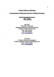
navigational and presentational treatment. As we will see, one of the key concepts in Pipe is the radical separation between content-link information and their navigational treatment. In Pipe, this is represented by the navigational schema and the relationship functions. This approach is similar to the philosophy presented in [9]. We are going to illustrate our approach by using the contents graph of a Web site with information about XML and related technologies. In this Web site we will have a general index that allows for the selection of any topic, the indexes about the selected topic, and the contents selected by every topic index. The application also presents some user adaptation capabilities, such as enabling the user to select the level of content detail. The contents of the Web site are structured according to the contents graph of Fig. 1. Note that throughout this paper we use the graphical representation of the Pipe structures, which are basically equivalent to their mathematical counterparts. (XML, aWhatIs, 1, whatIs, total) whatIs aWhatIs
XML
(index, aXMLWhatIs, 2, whatIs, total)
examples fundamentals tools
(index, aXMLWhatIs, 1, XML, total)
intro SAX aXMLWhatIs
fundamentals xmlDOM fundamentals1
index DOM
fundamentals2 examples
XSLT
intro fundamentals
XHTML
intro
content
definitions
anchor
evolution
link
examples
Fig. 1. Contents graph. In this static example the function r can be given by extension
The figure shows an index connected to both an XML index and whatIs content by a binary link. The index is connected to SAX, DOM, XSLT, and XHTML indexes and contents in the same manner. Finally, these topic indexes are connected with their content. In binary links the same anchor (i.e., aXMLWhatIs) originates two links, identified by the link number ((index, aXMLWhatIs, 1, XML, total), (index, aXMLWhatIs, 2, whatIs, total)), where the anchor total identifies to the whole content. In unary links every anchor (i.e., aWhatIs) only originates one link ((XML, aWhatIs, 1, whatIs, total)). This numbering is used by the browsing semantics. Note that in this graph there is no information about user adaptation capabilities. This is because it is a presentational characteristic independent of the graph structure. Indeed, in the final application (Fig. 8(b)) it is implemented by a folding list, independent of any hyperlink structure.
312
Antonio Navarro et al.
Although this contents graph was manually generated, the intended idea is to use the CASE support that we are developing, PlumbingMatic, to generate it, together with the other Pipe structures. All this information will be used in the prototyping phase, and reused in the design and development stages. 2.2
Navigational Schema (NS)
The Navigational Schema (NS), represents the user interface of the application (i.e., screens, panes, buttons) and the navigational paths established among and by the elements of the user interface. It is a tuple in which: − N is the set of Nodes of the application. − A is the set of Arcs of the application. The nodes of the application represent the elements of the navigational schema. There are nexus nodes (Nx) that represent the “windows” of the applications. They work as glue for the container nodes (Nc). These nodes represent the “panes” (concrete or virtual in the context sense of the Amsterdam model [10]) inside “windows”, and they act as the content holders (i.e., text, images, audio, etc.) of the application. Finally, there are nexus activator nodes (Na) that represent “buttons” inside “windows” that activate (by user selection) other “windows”. The arcs of the application represent the structural and timing connections between the elements of the navigational schema (i.e., the nodes). Therefore, A ⊆ (N × N × Y) ∪ (N × N × Ys × ℝ )
(4)
being Y = {connection, link} types of arcs among nodes, Ys = {sConnection, sLink}, types of synchronization arcs among nodes, and ℝ the set of Real Numbers. connections represent structural relationships between nexus and container nodes; links represents navigational paths between the elements of the navigational schema; sConnections and sLinks represent connections and links which are time activated, and ℝ characterizes the time information attached to both. In addition, restrictions in the relationships that can be established among the nodes appear. There is also a graphic notation to represent these sets (this graphic representation will be used in our case study), but both issues are beyond the scope of this paper [17]. Finally, these sets can be understood as a typed graph that we designate as extended graph. The set of navigational links between container nodes is called Pipes, P, P = { (ci, cj, link) ∈ A | ci ∈ Nc, cj ∈ Nc }
(5)
We call them pipes because they are going to be responsible for canalizing (interpreting) the links between contents (i.e., the elements of set L at the contents graph level) to the navigational level (i.e., in terms of set A). Regarding synchronization, Pipe´s approach is similar to the one presented in [23], where the basic structural and linking information is decorated with timing information (hence, the presence of sConnections and sLinks). Moreover, there are several functions that allow for the synchronization of the elements of the set N, based on other elements of the set. Again, we are going to obviate a description of these
Formal-Driven Conceptualization and Prototyping of Hypermedia Applications
313
functions, but their expressive power allows for complex timing relationships such as those presented in [11]. For example, if we want to describe a navigational schema composed by a window (x1) with three panes (c1, c2, and c3) such as the first one (c1) which has navigational paths (or pipes) with the other two, and the second (c2) which has another navigational path with the last one (c3), we should provide a navigational scheme such as the one shown in the Fig. 2. As in the contents graph, this navigational schema was manually constructed. The PlumbingMatic tool will support the development of such schemas. x1
c1
c2
c3
Fig. 2. Navigational schema. The square represents to the nexus node (x1). The circumferences represent to the container nodes (c1, c2, c3). The lines represent to the connections. The arrows represent to the links (pipes)
2.3
Canalization Functions (CF)
The Canalization Functions, relate the navigational schema to the contents graph assigned to it. It is a tuple , in which: − d is the content-assignation function. − l is the canalization function. − p is the presentation function. Function d is defined, d: Nc → (C ∪ {null})× ℘(C)
(6)
This function assigns a default content to every container node (it is assigned a value of null if there is no default content), and the set of contents that is going to appear inside this node (the set ℘ (X) denotes the powerset of X). This is done in the same manner that in [23]. Function l is defined, l: P → ℘ (L)
(7)
This function assigns the set of content-links that are going to be mapped (or canalized) in that way to every navigational path (or pipe) in the navigational schema. Several restrictions appear in the definition of function l, but are beyond the scope of this paper [17]. Finally, function p serves to assign presentation specifications to nodes and contents, allowing for the definition of the presentation semantics. Using the previous example, the navigational schema is going to be composed by one window (x1) with three panes (c1, c2, and c3). In the first one (c1) the general index will appear. In the second one (c2) the index of the topic selected in the general index will appear (hence the pipe between c1 and c2). In the third one the information selected by default in the general index (hence the pipe between c1 and c3), and the
314
Antonio Navarro et al.
information selected by the index of the theme (hence the pipe between c2 and c3) will appear. The relationships between navigational schema and contents graph are graphically shown in Fig. 3. Again, this figure was manually developed, but PlumbingMatic tool will be able to construct and relate the contents graph and navigational schema. Contents
Navigational schema
whatIs XML
examples fundamentals tools intro
SAX
fundamentals
x1
xmlDOM fundamentals1
index DOM
c1
c2
c3
fundamentals2 examples
XSLT
intro fundamentals
XHTML
intro definitions evolution examples
Fig. 3. Relationships between the navigational schema and the contents graph. The bold arrows represent the assignation of contents to navigational nodes (function d). Dotted links among contents are canalized by dotted pipe (function l). Dashed links among content are canalized by dashed pipe (function l). Solid links among contents are canalized by solid pipe (function l)
2.4
Browsing Semantics (BS) and Presentation Semantics (PS)
The Browsing Semantics (BS), represents the dynamic appearance of the application according to the interaction with the user. It is a tuple , in which: − a is the activation function. − f is the link-activation function. Before defining these functions we must introduce the sets: − Actives ⊆ V = N ∪ (N × ℝ ). Represents the set of active nodes, with their associated timing information.
Formal-Driven Conceptualization and Prototyping of Hypermedia Applications
315
− Show ⊆ S = (Nc × C) ∪ (Nc × C × ℝ ). Represents the contents that every container node shows (or plays), with their associated timing information. Function a is defined, a: Nx → ℘ (V) × ℘ (S)
(8)
where a(xi) = (Actives, Show). This function indicates what happens after a nexus node is activated. Basically, by default, every container node shows its content according to the timing information. Function f is defined, f: ((C × H) ∪ {⊥}) × N × ℘ (V) × ℘ (S) → ℘ (V) × ℘ (S)
(9)
where f((s, h), cj, Activesn, Shown) = (Activesn+1, Shown+1). This function (symbol ⊥ represents nexus-activator and time-activated links) indicates what happens after an anchor (h) source of n content-link ((s, h, 1, r(s, h, 1)), ..., (s, h, n, r(s, h, n))) is activated in a content (s) assigned to a container node (cj). Basically, the destination of every content-link (r(s, h, 1), ..., r(s, h, n)) is shown in the container node that holds it. It is necessary for every content-link to be canalized by (assigned to) a pipe that connects the container nodes. Function f presents several distinctions according to the content-link and the pipe that canalizes it. The complete description can be found in [17]. The Presentation Semantics(PS), is similar to the browsing semantics, but functions a and f include presentational information via function p. Note that the presence of PlumbingMatic tool will provide early prototypes without any real content. The information provided in Fig. 3 and the Pipe browsing semantics allows for the presentation of the contents graph according to the navigational schema using symbolic names instead of the real contents.
3
Plumbing Process Model
In this section we are going to present the Plumbing process model, evolution of the Fraternali/Ginige-Lowe [6], [8] process model depicted in Fig. 4. REQUIREMENT ANALYSIS
CONCEPTUALIZATION
PROTOTYPING AND VALIDATION
DESIGN
MAINTENANCE AND EVOLUTION
IMPLEMENTATION
CUSTOMER EVALUATION
Fig. 4. Fraternali/Ginige-Lowe´s process model
316
Antonio Navarro et al.
In requirement analysis, the mission of the software application is established by identifying prospective users and defining the nature of its information base. In conceptualization, the application is represented through a set of abstract models (Pipe in Plumbing) that convey the main components of the envisioned solution. In prototyping and validation, simplified versions of the applications are deployed to users for early feedback. In design, conceptual schemas are transformed into a lowerlevel representation, closer to the needs of implementation. In implementation, the final application is built. In customer evaluation, the user evaluates the final version. Previous iterations in conceptualization/prototyping stages permit a minor number of loops in design/implementation phases that are more costly in development resources. Finally, in evolution and maintenance the application continues its lifecycle. Our goal is to provide a specific description of the conceptualization and prototyping phases using the Pipe model. Therefore, the initial step at the conceptualization stage in Plumbing is to provide a Pipe-based representation of the main components of the application (with or without CASE support). The final purpose is to provide the sets and functions C, H, L, N, A, d, l, p, or equivalently a graphical representation (as in Fig. 3). Fig. 5 illustrates this Plumbing process model.
PROTOTYPING AND VALIDATION
REQUIREMENT ANALYSIS
CONCEPTUALIZATION
Mechanism for the structuring of the contents
Content Graph C, H, L
Contents and links of the application
Navigational Schema N, A Canalization Functions d, l, p Pipe representation of the application
Mechanism for relating contents and navigation
automatically a, f Representation of the application
Prototype
Navigational schema of the application
Mechanism for the structuring of the navigational sch.
Fig. 5. Conceptualization and prototyping in Plumbing process model
At the prototyping phase, mechanisms for the structuring of the contents and navigational schema must be provided, along with one to connect them. The mechanism for the structuring of the contents must be powerful enough to represent the structure of the contents graph, or equivalently the sets C, H, and L (e.g., a XML DTD with ID/IDREF attributes, or an entity-relationship diagram). The mechanism for the structuring of the navigational schema must also be powerful enough to represent the structure of the extended graph (e.g. a XML DTD or access primitives
Formal-Driven Conceptualization and Prototyping of Hypermedia Applications
317
as those provided by RMDM [12]), or equivalently the sets N and A. Using these structuring mechanisms, the contents of the application and their navigational schema are provided (i.e., the instances of the selected formalisms, or in other terms, the sets C, H, L, N, A). With the help of this data, we can build a Pipe representation of the canalization functions, that is, functions d, l, and p of the Pipe model can be coded. These functions can be used as the input of the automatic generator of prototypes that is guided by the Pipe browsing semantics. The construction of the navigational schema and its relationships with the contents (according to Pipe structures) can be done manually, or via some CASE tool (as PlumbingMatic) using Pipe structures to produce the specific data, input of the automatic generator of prototypes. Customers evaluate the prototype developed in this process in the following phase. Finally, the Pipe representation of the application, the prototypes built, and the ad hoc representation of the application are used in design and development phases. At the prototyping stage, the Plumbing process model does not determine any specific technique in the construction of the representation that codifies Pipe, and consequently, it does not imply any technology in the automatic generation of prototypes. Both techniques must be provided by the developers according to their specific needs. The next process model provides these specific techniques.
4
PlumbingXJ Process Model
PlumbingXJ is a particular example of a Plumbing process model where XML and Java are used to build a prototype of the application. PlumbingXJ is still a process model instead of a development technique because it does not provide specific development techniques, in the same manner that the use of specific techniques for requirements specification does not invalidate the nature of a process model [21]. Fig. 6 depicts PlumbingXJ. In this model two XML DTDs are the structuring mechanisms applied to content elements and to the navigational schema. The first, content DTD, is used to organize all the content elements in the application according to Pipe contents graph. The second, application DTD, is used to represent the navigational schema of the application according Pipe navigational schema. Content DTD is specific for each application, due to the specific nature of the contents that it is composed of. The structure provided by this type of DTD is double: a basic tree structure provided by XML elements and its content model (i.e., chapters, sections, etc.), and a superimposed graph structure provided by attributes (rendering the contents graph of the model). An instance of this DTD represents the actual contents of the application. We denominate it the content document and it codifies the sets C, H and L of the Pipe model. In the case of dynamically generated contents and links, set L must be characterized by intension, that is, in terms of the relationship function, r.
318
Antonio Navarro et al.
PROTOTYPING AND VALIDATION
REQUIREMENT ANALYSIS
Mechanism for relating contents and navigation
Content DTD CONCEPTUALIZATION
Content Graph C, H, L
Content document
XPath Navigational Schema N, A Canalization Functions d, l, p
Application document
APG a, f Prototype
Application DTD
Pipe representation of the application
Fig. 6. Conceptualization and prototyping in PlumbingXJ process model
Application DTD is unique and provides a formal vehicle for coding the navigational schema of the application. This DTD does not use Pipe vocabulary (i.e., nexus node, container node, etc.), using instead a more human-readable terminology (i.e., window, pane, etc.) to codify the Pipe model. The instance of this DTD is the navigational schema of the application, that is, it represents sets N and A of the Pipe model. According to the Plumbing process model, we should now specify how to relate both instances, or equivalently functions d, l, p. Although in the former model this was an independent step to obtain a greater generality, in PlumbingXJ it is accomplished at the same time that the navigational schema is provided (compare Fig. 5 and Fig. 6). Therefore, when building the instance of application DTD we are not only defining the set of windows and panes of the applications (sets N, A), but also the contents assigned to them as well as the way they are connected (functions d, l). The question is how to do it. The answer is called overmarkup. The key idea behind this technique is quite simple. The actual contents of the elements of this instance of the application DTD are XPath [28] references to the content document. These references select the contents that must appear in every pane (i.e., in every container node). Information about how to canalize the content links by the pipes (navigational links) must be also included. The “overmarked” document (the instance of the application DTD) is named application document. If existing contents or a content document need to be adapted, XSLT transformations [29] can be used instead of XPath references to obtain the actual contents from a previous one. Using the application document as the input for the Automatic Prototypes Generator (APG) simplified versions of the full application are built prior to its design allowing for early feedback. APG is a Java application that uses the DOM
Formal-Driven Conceptualization and Prototyping of Hypermedia Applications
319
representation [25] of an application document to generate a hypermedia application that works as a simplified representation of the final application. We generate a Java application instead of HTML pages directly because PlumbingXJ is not specific for Web applications, and because it permits a clearer separation between contents and navigation. As we have stated in Plumbing, this application document can be built manually according to Pipe representation, or it can be built using PlumbingMatic CASE tool. With independence of the concrete construction technique of this document, the application document, or equivalently the Pipe representation of the application, and the prototypes generated are valuable tools in the design and development of hypermedia applications. Although there is no a concrete implementation technique tied to PlumbingXJ, the approach presented in [20] can be a natural implementation technique. Moreover, the use of XML in the structuring of the documents offers an easy transition to HTML or another format using XSLT transformations. This approach is preferable to the direct use of HTML for prototyping due to the structuring power provided by XML [22].
5
PlumbingXJ Example
Requirement Analysis and Conceptualization The information provided through the paper covers this two phases. The Fig. 3 shows the principal outcome of the conceptualization phase. Prototyping Fig. 3 is a graphical representation of the Pipe description of the application. In Plumbing this representation has to be translated into a specific description used in the automatic generation of prototypes. In PlumbingXJ this description is provided by using XML. Fig. 7 depicts the application document for the Pipe representation of Fig. 3. window 1 /contents/index /contents/topics /contents/information
Fig. 7. Application document. Bold text implement overmarkup technique
320
Antonio Navarro et al.
When PlumbingMatic tool is available, the generation of Pipe structures depicted in Fig. 3 and its translation to application document in Fig. 7 will be automatic, but in this case it was manual. This document is the input of APG that generates the prototype shown in Fig. 8(a). The explicit separation among navigational schema and contents allows for the change in one aspect without affecting the other, easing the prototyping phase. At present the APG does not support Pipe n-ary links. Therefore, when the user selects a content in the main index, the default content does not appear in the third pane. We are working on a solution to this problem, which is inherently tied to APG implementation technologies (i.e., Java and HTML pages generated from XML data). The cycle among these three phases is iterated until the customer decides that the structure of the contents and the navigational schema are mature enough to begin the design and development stages of the final application. Design and Implementation The final application was built making an extensive use of XML technologies. The XML-marked documents were the basis for the generation of the HTML pages through the use of XSLT transformations. The adaptation capabilities were obtained using JavaScript to manipulate XML documents using DOM. The final result can be found in http://www.simba.vsf.es/FrameDoc.htm. Fig. 8(b) shows the final application corresponding to the prototype automatically generated in Fig. 8(a).
(a)
(b)
Fig. 8. Prototype generated (a) and final version of the application (b)
The availability of the representation of the application in Pipe notation, and the previously generated prototypes eased the development of the application as it was foreseen in the Fraternali/Ginige-Lowe process model. Of course, there were final adjustments, like the inclusion of a folding content index for each topic instead of the index originally conceived, but the main hypermedia structure remained unchanged.
Formal-Driven Conceptualization and Prototyping of Hypermedia Applications
6
321
Conclusions and Ongoing Work
The specific nature of hypermedia applications demands to pay more attention to the conceptualization and prototyping stages of the development process of this type of software [6], [8]. Classic hypermedia representation systems fail to solve these requirements due to their original conception as design tools, and/or to the lack of specific CASE support [1]. In this paper we have presented the Pipe hypermedia model, designed to represent key information about high-quality hypermedia applications, and specifically conceived as a conceptualization tool. This specificity simplifies its integration in a well-known process model [6], [8] and results in the Plumbing process model. Using markup technologies Plumbing is instantiated in PlumbingXJ, which permits the automatic generation of prototypes using the formalized default browsing semantics provided by Pipe. Moreover, the utilization of the application DTD makes easier the generation of prototypes and, up to the availability of CASE support, the use of XML based descriptive languages improves communication between customers and developers which allows faster changes in the prototyping phase. Finally, the existence of a Pipe based formal representation of the application, with total independence of a specific design, permits several reimplementations of the same application in different environments (e.g., CD-ROM and Web deployment), using a common informational framework. Ongoing research includes the extension of APG´s capabilities in order to support all Pipe expressive power, the use of alternative development techniques in Plumbing (giving processes similar to PlumbingXJ) and the use of Plumbing and PlumbingXJ in several applications under development. The next step in the project is the construction of the PlumbingMatic CASE tool. As future work, we are considering the possible evolution of PlumbingXJ into a specific development methodology.
Acknowledgments The Spanish Committee of Science and Technology (TIC2000-0737-C03-01 and TIC2001-1462) has supported this work. We would also like to thank the anonymous reviewers for their useful comments.
References 1. 2. 3. 4. 5.
Barry, C., Lang, M.: A Survey of Multimedia and Web Development Techniques and Methodology Usage. IEEE Multimedia 8 (3) (2001) 52-60 Bodner, R., Chignell, M.: Dynamic Hypertext: Querying and Linking. ACM Computing Surveys 31 (4) (1999) Bryan, M.: Guidelines for using XML for Electronic Data Interchange. http://www.xmledi-group.rog/xmledigroup/guide.htm (1998) Campbell B., Goodman J.M.: HAM: A general purpose hypertext abstract machine. Communications of the ACM 31 (7) (1998) 856-861 Diaz P., Aedo I., Panetsos F.: Labyrinth, an abstract model for hypermedia applications. Description of its static components. Information Systems 19 (4) (1994) 33-45
322 6. 7. 8. 9. 10. 11. 12. 13. 14. 15. 16. 17. 18. 19. 20. 21. 22. 23. 24. 25. 26. 27. 28. 29.
Antonio Navarro et al. Fraternali, P.: Tools and Approaches for Developing Data-Intensive Web Applications: A Survey. ACM Computing Surveys 31 (3) (1999) 227-263 Garzotto F., Paolini P., Schwabe D.: HDM: A model-based approach to hypertext application design. ACM Transactions on Information Systems 11 (1) (1993) 1-26 Ginige, A., Lowe, D.: Hypermedia Engineering: Process for developing large hypermedia systems. Tutorial at the Eighth ACM Conference on Hypertext. Southampton, UK, (1997) Halasz F., Schwartz M.: The Dexter Hypertext Reference Model. Communications of the ACM 37 (2) (1994) 30-39 Hardman L., Bulterman D.C.A., van Rossum G.: The Amsterdam Hypermedia Model: Adding Time and Context to the Dexter Model. CACM 37(2) (1994) 50-62 Hardman, L., van Ossenbruggen, J., Rutledge, L., Bulterman D.C.A.: Hypermedia: The Link with Time. ACM Computing Surveys 31 (4) (1999) Isakowitz T., Stohr E.A., Balasubramanian P.: RMM: a methodology for structured hypermedia design. Communications of the ACM 38 (8) (1995) 34-43 Millard, D. E., Moreau, L., Davis, H. C., Reich S.: FOHM: A Fundamental Open Hypertext Model for Investigating Interoperability between Hypertext Domains. In Proceedings of Hypertext 2000, San Antonio, Texas, (2000) 93-102 Muchaluat-Saade, D.C, Gomes, L.F.: Hypermedia Spatio-Temporal synchronization relations also deserve first-class status. In Proceedings of MMM 2001, Amsterdam, (2001) Nanard, J., Nanard, M.: An architecture model for the hypermedia engineering process. Proceedings IFIF EHCI’98 (Engineering of Human Computer Interaction), Creta, (1998) Navarro, A, Fernandez-Valmayor, A., Fernandez-Manjon, B., Sierra, J.L: Using Analysis, Design and Development of Hypermedia Applications in Educational Domain. Computer and Education, Kluwer Academic Publishers, Dordrecht, The Netherlands (2001) Navarro, A.: The Pipe Hypermedia Model. Software Engineering and Artificial Intelligence Group Universidad Complutense de Madrid Tech. Report ISIA-TR-2001-02. Peat B, Webber, D.: Introducing XML/EDI. http://www.xmledi-group.org/xmledigroup/start.html (1997) Schwabe D., Rossi G., Barbosa S.D.J.: Systematic Hypermedia Application Design with OOHDM. In proceedings of Hypertext 96, Washington D.C. (1996) Sierra, J.L., Fernandez-Valmayor, A., Fernandez-Manjon, B., Navarro, A.: Operationalizing Application Descriptions in DTC: Building Applications with Generalized Markup Technologies. In proceedings of SEKE 2001, Buenos Aires (2001) Sommerville, I.: Software Engineering. 6th Edition. Addison-Wesley (2001) Sperberg-McQueen, M.C., Goldstein, R.F.: HTML to the Max. A Manifesto for Adding SGML Intelligence to the WWW. Second World Wide Conference ´94, Chicago (1994) Stotts, P.D., Furuta, R.: Petri-Net-Based Hypertext: Document Structure with Browsing Semantics. ACM Transactions on Office Information Systems 7 (1) (1989) 3-29 Tompa F.: A Data Model for Flexible Hypertext Database Systems. ACM Transactions on Information Systems 7 (1) (1989) 85-100 World Wide Web Consortium, W3C Document Object Model (DOM). Level 1 Specification. http://www.w3.org/TR/1998/REC-DOM-Level-1-19981001/ (1998) World Wide Web Consortium, W3C Synchronized Multimedia Integration Language (SMIL 2.0), http://www.w3.org/TR/smil20/ (2001) World Wide Web Consortium, W3C Extensible Markup Language XML Specification DTD, http://www.w3.org/XML/1998/06/xmlspec-report-19980910.htm (1998) World Wide Web Consortium, W3C XML Path Language (XPath), Version 1.0, http://www.w3.org/TR/xpath (1999) [W3C XSLT] World Wide Web Consortium, W3C XSL Transformations (XSLT), Version 1.0, http://www.w3.org/TR/xslt (1999)