Formalizing Distributed Evolution of Variability in Information System Ecosystems Hendrik Brummermann1 , Markus Keunecke2 , Klaus Schmid2 1
Hochschul-Informations-System GmbH, Goseriede 9, 30159 Hannover, Germany
[email protected] 2 Software Systems Engineering, Institute of Computer Science, University of Hildesheim, Germany {keunecke, schmid}@sse.uni-hildesheim.de
Please cite this publication as follows: Hendrik Brummermann, Markus Keunecke, and Klaus Schmid. “Formalizing Distributed Evolution of Variability in Information System Ecosystems”. In: Proceedings of the 6th International Workshop on Variability Modeling of Software-Intensive Systems (VaMoS ’12). ACM, 2012, pp. 11–19. doi: 10.1145/2110147.2110149.
The corresponding BibTEX-entry is: @INPROCEEDINGS{BrummermannKeuneckeSchmid12a, author = {Hendrik Brummermann and Markus Keunecke and Klaus Schmid}, title = {Formalizing Distributed Evolution of Variability in Information System Ecosystems}, booktitle = {Proceedings of the 6th International Workshop on Variability Modeling of Software-Intensive Systems (VaMoS ’12)}, year = {2012}, pages = {11--19}, publisher = {ACM}, doi = {10.1145/2110147.2110149}, }
ACM, 2012. This is the authors version of the work. It is posted here by permission of the ACM for your personal use. Not for redistribution. The definitive version was published in Proceedings of the 6th International Workshop on Variability Modeling of Software-Intensive Systems (VaMoS ’12), doi: 10.1145/2110147.2110149.
Formalizing Distributed Evolution of Variability in Information System Ecosystems Hendrik Brummermann
Markus Keunecke
Klaus Schmid
Hochschul-InformationSystem GmbH Goseriede 9 30159 Hannover, Germany
University Hildesheim Institut fuer Informatik Marienburger Platz 2 31141 Hildesheim, Germany
University Hildesheim Institut fuer Informatik Marienburger Platz 2 31141 Hildesheim, Germany
[email protected]
[email protected]
[email protected]
ABSTRACT The open variability of software product line ecosystems allows customers and third party organizations to create extensions to a system which may refine the variability model. In this paper we will describe an approach to evolution support, which was developed in the context of one specific company, HIS GmbH. However, the approach is much more generic than this. In particular, it is based on the formalization of modifications to configuration values and constraints on both the model and the data in the context of the evolution of multi-level configurations. Our approach supports the identification of inconsistencies in evolution.
Categories and Subject Descriptors D.2.7 [Distribution, Maintenance, and Enhancement]; D.2.13 [Reusable Software]: Reuse Models; H.3.5 [Online Information Services]: Web-based services
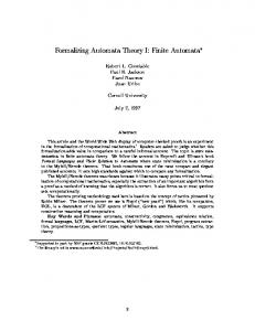
traditional product line engineering, because software can be developed by multiple organizations semi-independently. Therefore the development happens to some extent without explicit synchronization. In particular, a customizable software platform may be built by one organization, while another organization builds software on top of it without explicit information flow back to the first one [15]. Figure 1 describes a simplified situation focusing on only two organizations. Based on an original version (Vn ), the development organization releases a new version of the platform (Vn′ ) after some time. The changes done by third parties and customers (Vn+1 ) need to be merged with the evolved version Vn′ . This may lead to inconsistencies as there is no cross-organizational coordination. It is important to predict the consequences of such evolution steps in order to automatically or manually resolve conflicts before the new version is taken into production.
General Terms Design, Management, Experimentation
Evolution
Organization n
n tio iza
Variability Modeling, Evolution, Software Product Lines, Software Ecosystem
Vn '
m sto Cu
Vn
Keywords
1. INTRODUCTION
?
Organization n+1 Vn+1
Evolution in software ecosystems poses a number of challenges [5], which we are going to address by formalizing configuration values and constraints. While traditional product line approaches focus on the development within a single company [8, 19], more recent work extended the product line approach to product populations [20] and even further to software ecosystems [4]. In software ecosystems the situation is more complex than in
Time
Figure 1: Simplified distributed evolution issue in software ecosystems This situation leads to a stepwise approach similar to staged configuration based on feature models as described in [9]. In our situation, however, there is no global view on all configuration possibilities. This means that the individual stages are not limited to extending the model, but may redefine it. In other words they may add, modify and remove variation points, constraints and configuration values.
Permission to make digital or hard copies of all or part of this work for personal or classroom use is granted without fee provided that copies are not made or distributed for profit or commercial advantage and that copies bear this notice and the full citation on the first page. To copy otherwise, to republish, to post on servers or to redistribute to lists, requires prior specific permission and/or a fee. VaMoS ’12, January 25-27, 2012 Leipzig, Germany Copyright 2012 ACM 978-1-4503-1058-1 ...$10.00.
11
partly redefining existing configurations values. The customers typically do many changes to different areas of the system and may add their own parameters as well. Sometimes they define a second partial configuration that they enable in special situations or use for experiments. The effective configuration is a composition of the parts in the order they are defined.
Our configuration modeling approach is based on decision modeling, but modifies it to address concepts and particular issues of this situation. As an important step towards predicting the consequences of an update and assisting in the conflict resolution, we define a formalism for partial configurations and their composition. It is usable for both composing partial configurations of extensions and new partial configurations provided by updates. Furthermore, our approach supports the prediction of update consequences. It can detect inconsistencies before the new system is taken into production and assign blame to the appropriate parts of a configuration. The main challenge, we address in this paper, is the development of a formal approach to support multi-level configuration of products in a software product line ecosystem. An additional requirement is that each intermediate level of configuration should already result in a fully configured and thus usable system. The remainder of this paper is structured as follows: Section 2 describes the context and gives a summary of the arising issues. In the following section, we provide a formal definition of partial configurations and their composition before we look at evolution scenarios in Section 4. In Section 5, we will discuss related work, while Section 6 provides the conclusion and discusses further work.
2.2
Explicit global variability points are defined in a decision tree and affect the system as a whole such as the name of the university.
2. CONTEXT While our paper provides a novel and generic solution, it is inspired by a specific company context, which we describe in this section. We introduce the company and its open development model before we provide a formalized abstraction of real world configuration types in the following section. We conclude this section with a typical example, that we will use in further sections of this paper to illustrate our formalism. This example should be seen only as a reference example of an ecosystem. Our approach explicitly focuses on the generic situation.
2.1
Configuration types
HISinOne has a number of different configuration types that define the variability of various aspects of the system. According to Bosch this is common for real world systems [3]. Table 1 lists the most important configuration types in HISinOne and the number of entries in the base system. The numbers are lower bounds of the solution space variability because not all variation points are easily identifiable. The current system consists of configurations that are partly based in the problem space and partly based in the solution space. Furthermore the complete problem space is not known to HIS as third party organizations may extend or modify the system in unforeseen ways. HIS therefore tries to provide a very flexible basis for the solution space. HIS distinguishes the following configuration types for practical reasons:
Decentralized variability points allow different effective values at the same time, depending on the area they are used in. For example, the application form looks different depending on requirements defined by the course of study. This kind of variability was omitted from Table 1 because there is no easy way to count it. Layout and Design are mostly implemented by using the web technology Cascading Style Sheets. Customers often adapt it to their cooperate design by changing the color schema for example. Changes can be very complex and completely redefine the layout.
Case Study
Our context is a German university management system called HISinOne, which is the core of its own software ecosystem. The open development model of the development organization HIS GmbH enables universities to adapt and extend HISinOne independently to fit their needs. Often customers contract the solution department of HIS or independent service providers to aid with the configuration. Third party vendors develop extensions or alternatives for parts of the HISinOne system with which HISinOne has to work together at the customers’ sites. The software needs to be very flexible because requirements among customers are quite different: Customers range from small universities of applied science to huge universities focusing on research. Furthermore Germany is divided into 16 regional states with different laws regarding the regulation of universities. The different levels of autonomy require flexibility that reaches deeply into the core of the system. For example validation and calculation rules and business processes need to be adaptable. HIS provides a base configuration that is common to all installations. Furthermore it provides different sets of partial configurations specific to segments of customers. The example in Figure 2 shows a typical situation with a third party vendor adding its own configurations parameters and
User interface texts are managed outside the user interface definitions because they need to be translated into different languages and adapted to specific vocabulary of the customer. User interface texts are used for both labels of input fields and long help texts. Configuration type Explicit global variability points Layout and Design User interface texts Explicit default constraints Explicit required constraints Implicit constraints Tables Columns Rows of default reference data Sum
Count 872 2905 10117 689 185 8749 669 5124 162135 191445
Table 1: Number of variation points in HISinOne as of 16th October 2011
12
Explicit default constraints are applied to both operational data and configuration values, but can be overridden by customers. For example many universities use lecture numbers which are configured as mandatory fields by default. Explicit required constraints are useful to enforce technical and law-based restrictions such as requiring a registration number for students. Unlike default constraints, customers may not remove them. Implicit constraints are derived from the data model and applied automatically in the service and user interface layers. For example, an attribute that is defined as integer will not accept a text literal and a field with a not-null database-constraint is mandatory.
Figure 2: Composition of default values defined by the development organization, a third party vendor and the customer
Tables and columns are used to store the data and customers can add their own tables and columns. Default and required constraints can be defined for any column.
for the grade of the school certificate, which is visible (app.grade.visible) and has a mandatory default constraint (app.grade.mandatory).
Default reference data consists of reference data such as a list of all universities or configuration information for algorithms.
E2 Now a customer implements the university management software at his site and adopts it to fit his needs. Here we assume that the customer is an Art School. It does not need a grade of the school certificate and disables the constraint which forced the grade to be mandatory. The customer even goes a step further and hides the input field from the user interface (app.grade.visibility). To make the dialogue better understandable for the applicants the customer also changes the help text (app.helptext) to explain the application requirements for the Art School.
Using these specialized configuration types seems reasonable from an administrator’s point of view. On a more abstract level they show huge similarities concerning the composition and merging of partial configurations on updates. They can be grouped into configuration values and constraints. HIS distinguishes between constraints that are required by all installations and default constraints. An example for a required constraint is: “If it is a German university, the registration number of students is a mandatory field” (because it is required by law). Customers are not able to disable this constraint. The number of a lecture, however, is treated differently for domain reasons: Many universities want their lectures to have short visible numbers in order to be able to refer to them easily. But a small number of universities do not use this number. HIS provides a default constraint “the lecture number is a mandatory field”. Unlike the constraint on registration number, customers may remove this constraint on the lecture number. In this paper, we focus on explicitly defined variability including user interface texts and layout definitions. Our approach will work for decentralized variability points, too, if they are identifiable by some kind of name.
2.3
E1’ After some time the customer wants to update to the newest version released by the development organization. But in the meantime changes to law occurred requiring the grade of school certificates for statistic reasons. The development organization has therefore evolved the software: The constraint making the grade of school certificates mandatory was taken from a default constraint to a required one. This results in a conflict: The Art School configuration is no longer allowed to set the grade to not mandatory. In the next section, we will describe our approach to dealing evolution problems like this. As a basis for this, we will first define in a strictly formal manner our concept of a configuration.
Example from the applicant management domain
In this section, we will describe an example from the applicant management domain which we will use as a running example throughout this paper. Applicant Management is a part of the system that customers commonly change. First, we describe the base configuration of the system as delivered by HIS. Then we give an example of a customer modification. Our scenario ends with a realistic update of the base configuration.
3. COMPOSING CONFIGURATIONS In this section, we will introduce configuration modeling, which is similar to decision modeling but allows metavariability [16] in the sense that the variation model itself is variable, as constraints may be redefined. Partial configuration consists of values and constraints that can be defined and redefined on every level. After defining a composition of partial configurations we conclude this section with an approach for detecting inconsistencies.
E1 In a base configuration the system provides a wizard for applicants to enter the data which is required for their application such as contact information and qualification. The dialogues contain a number of input fields and help texts. For example, there is an input field
3.1
Value Configurations
In this section, we formally define partial value configurations, which have been described informally in Section 2.
13
monotonous extensions. Thus, constraints may not be considered a fixed part of a configuration, resulting in a kind of meta-variability. Another extension is that constraints are applied to both configuration values and data in the database. For example many universities assign visible numbers to lectures for easy reference. Therefore the development company provides a base configuration in which the lecture number is mandatory. But a customer may decide not to use lecture numbers and remove this constraint. In addition to these default constraints, there are required constraints that may not be modified because they are required for technical or domain-specific reasons. For example, the grade of the school certificate is required by statistic law in Germany, so a German university may not remove this constraint. Default and required constraints can exist on all levels of partial configurations, not just the base configuration. This requires that we must be able to redefine constraints. We use names to identify constraints as a later defined default constraint may override an earlier one.
Value configurations assign values to configuration variables. Therefore we define: Definition 1. The set of all configuration variables is called V. Due to the distributed nature of software ecosystems the subset of all used configuration variables is not known to the development company, because customers may add their own configuration variables. Definition 2. The set of all possible configuration values is called W. For simplicity, we do not distinguish multiple types. An extension could be made easily. Definition 3. Let V ⊆ V be a subset of configuration variables, then Cvalue (V, c ∶ V → W) is called a partial value configuration, if c ∶ V → W is a total function assigning values to configuration variables. We refer to values assigned in a configuration as default values, because in a composition later configurations may override them. After all partial configurations are composed, the remaining set of default values is effective.
Definition 5. The set of all names is called N. N is analogous to the set of all variables V in value configurations. Analogous to the set of all values W, we define a set of all possible constraints.
Definition 4. A partial value configuration Cvalue (V, c ∶ V → W) is called a full value configuration over a variable set V ′ if V = V ′ .
Definition 6. The set of all possible constraints is called
The example in Section 2.3 defines that the dialog for the application has the help text “Welcome to the application wizard” and a visible input field for grades with the help text “Grade of school certificate”. In our formalism this can be described as CvalueE1 = ( V = {app.helptext, app.grade.helptext, app.grade.visible}, c(app.helptext) = “Welcome to the application wizard” c(app.grade.helptext) = “Grade of school certificate” c(app.grade.visible) = true )
3.2
Constraint Configurations
P. For example HISinOne currently supports the following constraint types: ● value must be provided ● ranges defined by minimum and maximum numbers ● length limit of text fields ● formats defined by regular expressions ● additional datatypes such as “academic-term” and “datein-the-past”
Unlike traditional variability modeling approaches, in our approach customers are able to modify existing constraints and add new ones. Derived projects are not restricted to
● programmed special purpose and multi-field constraints such as “the number of years between the day of birth and the day of application must be below a configured value” that can be plugged in Multiple constraints are combined using an AND-semantics. Our concept, however, is not limited to the above types. A partial constraint configuration consists of default constraints and required constraints. Default constraints are uniquely identified by names, so that replacement or modification of constraints can be identified. Required constraints, however, cannot be replaced but only added. Therefore the same identifier may refer to multiple constraints. The identifiers are still useful, however, because they allow to keep track of constraints. Definition 7. Let Nd ⊆ N and Nr ⊆ N be two sets of names, then Cconstraint (Nd , Nr , d ∶ Nd → P, r ∶ Nr → 2P ) is called a partial constraint configuration, if d is a total function assigning default constraints to names and r is a total function assigning a set of required constraints to names.
Figure 3: Adding additional required constraints without being able to override existing ones
14
In example E1, the grade is a mandatory field because of a default constraint: CE1 = ( Nd = {app.grade.mandatory}, Nr = {}, d(app.grade.mandatory) = grade is mandatory ) For simplicity, we assume that partial constraint configurations are consistent within themselves.
3.3
For the enforcement of constraints in an installation, we do not need to distinguish between default and required constraints. Therefore we can define a function π, which extracts all constraints from a given configuration and puts them into one joint set. Definition 12. Let C(V, Nd , Nr , c ∶ V → W, d ∶ Nd → P, r ∶ Nr → 2P ) be a partial configuration. Then we define a predicate extraction function π ∶ C → 2P with π(C) = {d(nd )∣nd ∈ Nd } ∪ {p∣p ∈ r(nr ), nr ∈ Nr }.
Configurations
A partial configuration consists of both the value and the constraint components:
In order to detect certain inconsistencies, we have to apply predicates to installations and configurations:
Definition 8. Let Cvalue (V, c ∶ V → W) be a partial value configuration and Cconstraint (Nd , Nr , d ∶ Nd → P, r ∶ Nr → 2P ), then we call C(V, Nd , Nr , c ∶ V → W, d ∶ Nd → P, r ∶ Nr → 2P ) a partial configuration. The set of all partial configurations is named C.
Definition 13. Let I(C, Data) be an installation with a configuration C(V, Nd , Nr , c ∶ V → W, d ∶ Nd → P, r ∶ Nr → 2P ) and Data = {reci ∣i ∈ N}, then we define the evaluation of a predicate p as predicate function p(c, rec). If p is independent of data, we may use a boolean function p(c) instead.
Note, that constraints can force a specific value for a given configuration variable, so there is no need for required values as an explicit component of configurations. Applying our formalism to the examples given in Section 2.3 results in the configurations shown in Table 2:
Using the above definitions, we can now define what consistency means for our kinds of constraints.
3.4.2 Inconsistency Detection The inconsistencies, we found in practice, can be categorized as follows:
● The initial base configuration (E1) created by the development organization defines some help texts and a visible and mandatory input field for grades.
CR1 configurations values must comply with constraints CR2 data must comply with constraints
● The customer’s local customization (E2) hides the input field for grades and removes the constraint. It changes the help text.
CR3 the set of constraints must not be inconsistent We will look at each of these requirements in turn:
● The evolved base configuration (E1’) defines some help texts and a visible input field for grades. The constraint making the grade mandatory is required and may not be removed.
3.4
Configurations values must comply with constraints An example for the inconsistency of values (CR1) is hiding the input field for grades, although there is a constraint forcing the visibility to true. To detect an inconsistency in values, all constraints can simply be evaluated on all configuration values, as they are known:
Consistency Analysis
In this subsection, we define the requirements for consistent configurations. Before we look at the detection of inconsistencies, we define how constraints are evaluated.
Definition 14. Let C(V, Nd , Nr , c ∶ V → W, d ∶ Nd → P, r ∶ Nr → 2P ) be a configuration, then there is a value inconsistency, if ∃p ∈ π(C) ∶ p(c) = f alse
3.4.1 Evaluation of Constraints
Data must comply with constraints For the second category (CR2), we assume there is an applicant record in the database that does not have a grade specified. This will result in a data inconsistency, if there is a mandatory constraint for the grade. In order to detect this inconsistency, all constraints are applied to all records existing in the database:
As explained in Section 2.2, constraints can be applied to configuration values and data in a database. A database consists of records, therefore we define: Definition 9. We call Rec the set of all possible data records. For simplicity and without loss of generality, we look at a database as the product of all tables (T able1 × T able2 × T able3 . . . ):
Definition 15. Let I(C, Data) be an installation with C(V, Nd , Nr , c ∶ V → W, d ∶ Nd → P, r ∶ Nr → 2P ), then there is a data inconsistency if ∃rec ∈ Data, p ∈ π(C) ∶ p(c, rec) = f alse
Definition 10. A database is a non empty subset of Rec consisting of homogeneous records with the same cardinality and type-structure.
The set of constraints must not be inconsistent Constraints may contradict each other in a configuration, thus it is impossible to fulfill them all at once (CR3). For example a constraint forces the registration number to be exactly 6 digits long and another constraint forces it to be smaller than the number 100,000. Contradicting constraints may exist on both configuration values and the data.
An installation consists of a configuration and a database. Definition 11. Let C be a configuration and Data be a database, then I = (C, Data) is called an Installation. The set of all installations is named I.
15
E1: Original configuration by development org. CE1 = ( V = {app.helptext, app.grade.helptext, app.grade.visible}, Nd = {app.grade.mandatory}, Nr = {}, c(app.helptext) = “Welcome to the application wizard”, c(app.grade.helptext) = “Grade of school certificate”, c(app.grade.visible) = true, d(app.grade.mandatory) = true ) E2: Partial configuration by the customers CE2 = ( V = {app.helptext, app.grade.visible}, Nd = {app.grade.mandatory}, Nr = {}, c(app.helptext) = “Welcome to Aster Art School”, c(app.grade.visible) = f alse, d(app.grade.mandatory) = f alse )
E1’: Evolved configuration by development org. CE1′ = ( V = {app.helptext, app.grade.helptext, app.grade.visible}, Nd = {}, Nr = {app.grade.mandatory}, c(app.helptext) = “Welcome”, c(app.grade.helptext) = “Grade of school certificate”, c(app.grade.visible) = true, r(app.grade.mandatory) = {true} )
unchanged, see left
Table 2: A formal representation of configuration examples Evolved effective configuration CE1′ ⊲ CE2 = ( V = {app.helptext, app.grade.helptext, app.grade.visible}, Nd = {app.grade.mandatory}, Nr = {app.grade.mandatory}, c(app.helptext) = “Welcome to Aster Art School”, c(app.grade.helptext) = “Grade of school certificate”, c(app.grade.visible) = f alse, d(app.grade.mandatory) = f alse, r(app.grade.mandatory) = {true} )
Effective configuration CE1 ⊲ CE2 = ( V = {app.helptext, app.grade.helptext, app.grade.visible}, Nd = {app.grade.mandatory}, Nr = {}, c(app.helptext) = “Welcome to Aster Art School”, c(app.grade.helptext) = “Grade of school certificate”, c(app.grade.visible) = f alse, d(app.grade.mandatory) = f alse )
Table 3: Effective configurations after composition of the configurations shown in Table 2 Nr = {}, d(app.grade.length) = 6, d(app.grade.smaller) = 100, 000,
Definition 16. Let C be a configuration, then there are inconsistent constraints, if: ∀(c ∶ v → W) ∶ ∃p ∈ π(C) ∶ p(c) = f alse or ∀rec ∈ Rec, ∀(c ∶ v → W) ∶ ∃p ∈ π(C) ∶ p(c, rec) = f alse
)
Summary To summarize the three categories of inconsistency we define:
A minimal inconsistent installation is the smallest installation with a problem. Therefore removing any entry from this installation makes it consistent. In other words: There can be no other sub installation which is still inconsistent.
Definition 17. Let I(C, Data) be an installation, then we call a function check ∶ I → {true, f alse} consistency check defined as follows: check(I) = f alse, if I has at least one of the 3 inconsistencies check(I) = true, otherwise
Definition 18. Let I(C, Data) be an installation with C(V, Nd , Nr , c ∶ V → W, d ∶ Nd → P, r ∶ Nr → 2P ). Then we call I minimal inconsistent installation, if: check(I) = f alse and ∀I ′ ∶ check(I ′ ) = true and I ′ (C ′ , Data′ ) with C ′ (V ′ , Nd′ , Nr′ , c′ ∶ V ′ → W, d′ ∶ Nd′ → P, r′ ∶ Nr′ → 2P ) is an installation with V ′ ⊆ V, Nd′ ⊆ Nd , Nr′ ⊆ Nr , c′ ⊆ c, d′ ⊆ d, r′ ⊆ r, I ≠ I ′
The interesting entries of an inconsistent installation are those that cause the inconsistency: For example there may be a complex partial configuration which defines many values and constraints. The following minimized configuration already shows an inconsistency without having to take other values and constraints into account: C( V = {}, Nd = {app.grade.length, app.grade.smaller},
Please note, that the condition I ≠ I ′ forces I ′ to be a truly smaller installation in at least one of the components. The minimal inconsistent installation is not uniquely specified. Nevertheless it can be a very useful tool in practice, because it reduces the amount of work for administrators significantly: In case of an inconsistency an administrator has to resolve the problem. A typical configuration consists of hundreds of configuration variables and constraints as shown in the table
16
Definition 21. Let C1 and C2 be partial configurations defined as follow: C1 (V1 , Nd1 , Nd2 , c1 ∶ V1 → W, d1 ∶ Nd1 → P, r1 ∶ Nr1 → 2P ) C2 (V2 , Nd2 , Nr2 , c2 ∶ V2 → W, d2 ∶ Nd2 → P, r2 ∶ Nr2 → 2P )
in Section 2.2, thus minimizing the number of entries, that have to be examined manually.
3.5
Composition
As discussed in Section 2, there is a sequence of partial configurations starting with a base configuration provided by the development company and ending with the last configuration by the customer. There may be multiple partial configurations in between to configure the system for different kinds of customers. Later configurations in the sequence can redefine default values and default constraints and add their own ones as shown in Figure 2. They can also add required constraints, but may not remove or modify them as shown in Figure 3.
Then the difference ∆ ∶ C2 × C1 is defined as: ∆(C2 , C1 ) = ( Vadded = V2 ∖ V1 Vmodif ied = {v∣v ∈ V1 ∩ V2 , ∨c1 (v) ≠ c2 (v)} Vdeleted = V1 ∖ V2 Ndadded = Nd2 ∖ Nd1 Ndmodif ied = {n∣n ∈ Nd1 ∩ Nd2 , Nd1 (n) ≠ Nd2 (n)} Nddeleted = Nd1 ∖ Nd2 Nradded = Nr2 ∖ Nr1 Ndmodif ied = {n∣n ∈ Nr1 ∩ Nr2 , Nr1 (n) ≠ dr2 (n)} Nrdeleted = Nr1 ∖ Nr2 )
Definition 19. Let C1 and C2 be partial configurations defined as follows: C1 (V1 , Nd1 , Nr2 , c1 ∶ V1 → W, d1 ∶ Nd1 → P, r1 ∶ Nr1 → 2P ) C2 (V2 , Nd2 , Nr2 , c2 ∶ V2 → W, d2 ∶ Nd2 → P, r2 ∶ Nr2 → 2P )
The difference can be used to explore all changes in a new version of a partial configuration. This is especially useful as a diagnostic tool because it helps administrator to find the root cause of problems quickly, that may show up in the production system after a configuration change or extension. Note, that the difference operator is aware of the structure of configurations. Unlike line-based difference tools it abstracts from syntactic changes as discussed in [2]. On updates, it is important to identify effective changes on an installation. Those can be calculated by applying the difference operator to the original and updated effective configuration. This will hide changes to variables and constraints that have been overridden, as they are not part of the effective configuration. In the example shown in Table 2 the development company changes a default constraint to a mandatory constraint. Applying the ∆ operator to these partial configurations will result in: ∆(CE1′ , CE1 ) = ( Vadded = {} Vmodif ied = {} Vdeleted = {} Ndadded = {} Ndmodif ied = {} Nddeleted = {app.grade.mandatory} Nradded = {app.grade.mandatory} Ndmodif ied = {} Nrdeleted = {} ) This identifies the key changes, which the customer’s administrator has to look at in detail.
Then a composition ⊲∶ C1 × C2 is defined as: ⊲ (C1 , C2 ) = C(V, Nd , Nr , c ∶ V → W, d ∶ Nd → P, r ∶ Nr → 2P ) with: V = V1 ∪ V 2 Nd = Nd1 ∪ Nd2 Nr = Nr1 ∪ Nr2 ∀v ∈ V ∶ c(v) = c2 (v), if v ∈ V2 ; c1 (v) otherwise ∀n ∈ Nd ∶ d(n) = d2 (n), if n ∈ Nd2 ; d1 (n) otherwise ∀n ∈ Nr ∶ r(n) = r1 (n) ∪ r2 (n) C1 ⊲ C2 is read as C1 before C2 . Table 3 shows the result of composing our examples E1 with E2 and E1’ with E2: Composing the examples E1 and E2 results in the input field for grades being hidden and help texts being changed according to the customer configuration. The composition of E1’ and E2 is very similar, but has an additional required mandatory constraint on the grade. This example shows that composing two consistent configurations may result in an inconsistent configuration. Definition 20. Let S = (C1 , C2 , . . . Cn ) be a sequence of partial configurations, then we call CE the effective configuration over S, if CE = C1 ⊲ C2 ⊲ ... ⊲ Cn . For simplicity, we may call CE the effective configuration.
4. EVOLUTION
4.2
This section describes how our approach introduced in Section 3 helps in the actual evolution situations between two configurations. First, we will introduce differences between configurations and how they help in the analysis of error situations. Furthermore, we will explain how the inconsistency detection from Section 3.4 helps predicting the consequences of an update.
4.1
Consistency
Consistency of installations is especially important in the context of evolution: While the composition of consistent partial configurations can result in an inconsistent effective configuration, this is usually not an issue during the initial deployment because the local customizations are developed with the base configuration in mind. Therefore issues are resolved during the customer’s development and a lengthy testing process ensures that the system fulfills the customer’s needs before it is taken into production. Updates, however, are merge situations: Although an old partial configuration is simply replaced by a new one, the partial configurations following in the sequence are now applied to the new configuration resulting in a different effective configuration. It is desirable to spend less time on qual-
Difference between two configurations
The evolution of configurations may lead to problems as described at the end of Section 3. In such a case, it is important to identify the effective changes that occurred as a basis for determining the problem source. Here, we will formalize the notion of the difference of two configurations.
17
ity assurance compared to the test during the development of the initial customization. The new base configuration and the old customer configuration may be in conflict on some parts. Table 3 shows the effective configurations of our example. The original customer configuration E2 leading to the effective configuration E1 ⊲ E2 was developed with the base configuration in mind. Therefore the customer was able to set the undesired default constraint d(app.grade.mandatory) to f alse. After some time the development company released version E1′ . In general there are three possible outcomes of changes: Conflict: E1′ contains a required constraint r(app.grade. mandatory) set to {true}. The composition of E1′ ⊲ E2′ results in a new effective configuration which requires the grade to be both mandatory and not mandatory at the same time. This is an inconsistency as defined in Section 3.4 because the constraints are contradicting each other. Overridden: Another change done by the development company in E1′ is the value “Welcome” for the configuration variable app.helptext which used to be “Welcome to the application wizard”. This change is not part of the effective configuration because the university defined its own title “Welcome to Aster Art School”. Effective: In practice most changes, however, make it into the effective configuration because they are related to new functionalities or customers have not modified the affected variables or constraints. Therefore the minimal inconsistent installation as defined in Section 3.4 is a valuable tool to focus on the problematic parts. As a customer is not able to modify the partial configuration provided by the development company, it is helpful to highlight those parts of the minimal inconsistent installation that the customer may change. Note that for conflicts, in which default constraints are involved, overriding that constraint is a valid option. The same mechanism can be used by the development company to identify changes before a release that will have a negative impact on customer installations, if the development company has access to (anonymized) copies of customer installations.
Czarnecki et al. [9] introduce the concept of staged configuration with multi-level configuration as a special form with separate feature models for each stage. Classen et al. [7] formalize the process of staged multi-level configuration. Staged configuration is described as a process that prunes down the number of possible decisions with each configuration stage, while our approach allows to extend and redefine the variability model at each level. Stoiber et al. [18] also refers to staged configuration and discusses the impact of constraints in a stepwise configuration process. Although Stoiber considers the consistency of products, the aspects considered in his paper do not cover evolution in a distributed scenario as we do here. Mazo et al. [13] discuss the validation of variability represented as decision models. This is also important in our context, but their setting is not distributed and with central coordination. Furthermore, we go one step further by validating existing data with the variability model. Gamez et al. [10], Cavalcanti et al. [6] and Anastasopoulos et al. [1] discuss the evolution of variability models. They focus on centralized situations. Apel et al. [2] discuss distributed evolution with explicit synchronization. In our context, however, evolution occurs distributed across multiple organizations with little or no synchronization. Similar issues exist outside the area of information systems: The approaches of the Eclipse and Debian communities are discussed by Schmid et al. in [15]. Both the Eclipse and Debian community are good examples for current industrial practice, although their focus is not on information system. At the database level Siegmund et al. in [17] and Schaeler in [14] describe approaches for modularization and merging of fragments. Nonetheless their findings on database modularization do also apply in a distributed context. In contrast to our situation both papers do not consider possible issues for evolution.
6. CONCLUSION We defined a formalism for the composition of variability in software ecosystems and showed how this helps to address the distributed product line evolution. Our approach is based on partial configurations, which may be provided by different organizations such as the development company, third party vendors and customers. A partial configuration consists of modifiable configuration values, modifiable constraints and required constraints. Constraints may be defined on both configuration values and data in the database of an installation. Later configurations in the sequence are not limited to “fill in the gaps”, but may extend the system and redefine parts that have been provided by previous partial configurations. This allows the development company to provide default constraints, that are useful for many customers, while enabling customers to override them to achieve their desired behavior. This goes well beyond existing approaches to product line variability, which often do not provide characteristics such as default values, composition of partial configurations or constraints on database information. However, all those characteristics are a must for the kind of products and the development environments, we are concerned with. Our approach describes in a strictly formal manner how partial configurations can be composed and how inconsistencies are detected. Our formalism supports structured
5. RELATED WORK The context of our work is a software ecosystem according to the definition given by Bosch [4] or Schmid [15]. Van Ommering [20] introduced the notion of product populations. This is related to our work as we include an open variability model which is defined in a distributed way. In contrast to the situation discussed in this paper, Van Ommering assumes a central authority controlling the product lines. Krueger describes an approach to partial instantiation of software product lines with updates, feedback and crossmerges in [11]. In our situation feedback from customers is not complete and cross-merges are the common case. In [12] Krueger describes mass customization and automatic derivation of products. This is related to our situation because customers basically create their own products based on a configuration infrastructure.
18
[8] P. Clements and L. Northrop. Software product lines: Practices and patterns. Addison-Wesley, 2001. [9] K. Czarnecki, S. Helsen, and U. Eisenecker. Staged configuration through specialization and multi-level configuration of feature models. Software Process: Improvement and Practice, 10(2):143–169, 2005. [10] N. Gamez and L. Fuentes. Software product line evolution with cardinality-based feature models. In Proceedings of the 12th International Conference on Software Reuse, (ICSR ’11), pages 102–118, 2011. [11] C. Krueger. Towards a taxonomy for software product lines. In Proceedings of the 5th International Workshop Software Product-Family Engineering (PFE ’03), volume 3014 of Lecture Notes in Computer Science, pages 323–331. 2004. [12] C. Krueger. New methods in software product line development. In Proceedings of the 10th International Software Product Line Conference (SPLC ’06), pages 95–102, 2006. [13] R. Mazo, P. Gr¨ unbacher, W. Heider, R. Rabiser, C. Salinesi, and D. Diaz. Using constraint programming to verify DOPLER variability models. In Proceedings of the 5th Workshop on Variability Modelling of Software-Intensive Systems (VaMoS ’11), pages 97–103, 2011. [14] M. Sch¨ aler, T. Leich, N. Siegmund, C. K¨ astner, and G. Saake. Generierung maßgeschneiderter Relationenschemata in Softwareproduktlinien mittels Superimposition. 14. GI-Fachtagung Datenbanksysteme f¨ ur Business, Technologie und Web, pages 250–261, 2011. [15] K. Schmid. Variability modeling for distributed development — a comparison with established practice. In Proceedings of the 14th International Conference on Software Product Line Engineering (SPLC’10), pages 155–165, 2010. [16] K. Schmid and H. Eichelberger. Model-based implementation of meta-variability constructs: A case study using aspects. In Proceedings of the 2rd International Workshop on Variability Modelling of Software-intensive Systems (VaMoS ’08), pages 63–71, 2008. [17] N. Siegmund, C. K¨ astner, M. Rosenm¨ uller, F. Heidenreich, S. Apel, and G. Saake. Bridging the gap between variability in client application and database schema. 13. GI-Fachtagung Datenbanksysteme f¨ ur Business, Technologie und Web, pages 297–306, 2009. [18] R. Stoiber and M. Glinz. Supporting stepwise, incremental product derivation in product line requirements engineering. In Proceedings of the 4th International Workshop on Variability Modelling of Software-intensive Systems (VaMoS ’10), pages 77–84, 2010. [19] F. v. d. Linden, K. Schmid, and E. Rommes. Software product lines in action: the best industrial practice in product line engineering. Springer, 2007. [20] R. van Ommering. Building product populations with software components. Proceedings of the 24th International Conference on Software Engineering (ICSE ’02), pages 255–265, 2002.
difference calculations, which is especially helpful to fix issues very quickly in a production system that occurred after a configuration change. After an update provided by the development company or a third party vendor, those changes have to be merged with the local customization done by the customer. A full installation consists of a huge amount of data and a large number of configuration values and constraints. Therefore we showed how a minimal inconsistency set is calculated, which lets administrators focus on the important parts of the configuration in order to resolve the conflicts. While we provided a formal basis, much work still needs to be done: To validate our formalism we are going to implement it in tools. We have already implemented the composition of configurations and the difference calculations for some configuration types such as user interface texts and CSS layout rules. We will continue our work by implementing the detection of inconsistencies in installations before they go intro production and support administrators by identifying the minimal changes required to repair the system.
7. REFERENCES [1] M. Anastasopoulos, D. Muthig, T. Burgos de Oliveira, E. Almeida, and S. Romero de Lemos Meira. Evolving a software product line reuse infrastructure a configuration management solution. In Proceedings of the 3rd International Workshop on Variability Modelling of Software-intensive Systems (VaMoS ’09), 2009. [2] S. Apel, J. Liebig, C. Lengauer, C. K¨ astner, and W. Cook. Semistructured merge in revision control systems. In Proceedings of the 4th International Workshop on Variability Modelling of Software-intensive Systems (VaMoS ’10), pages 13–19, 2010. [3] J. Bosch. Maturity and evolution in software product lines: Approaches, artefacts and organization. In Proceedings of the 2nd Conference Software Product Line Conference (SPLC’02), pages 257–271, 2002. [4] J. Bosch. From software product lines to software ecosystems. In Proceedings of the 13th International Software Product Line Conference (SPLC’09), pages 111–119, 2009. [5] H. Brummermann, M. Keunecke, and K. Schmid. Variability issues in the evolution of information system ecosystems. In Proceedings of the 5th Workshop on Variability Modeling of Software-Intensive Systems, pages 159–164, 2011. [6] Y. C. Cavalcanti, I. do Carmo Machado, P. A. da Mota, S. Neto, L. L. Lobato, E. S. de Almeida, and S. R. de Lemos Meira. Towards metamodel support for variability and traceability in software product lines. In Proceedings of the 5th Workshop on Variability Modelling of Software-Intensive Systems (VaMoS ’11), pages 49–57, 2011. [7] A. Classen, A. Hubaux, and P. Heymans. A formal semantics for multi-level staged configuration. In Proceedings of the 3rd International Workshop on Variability Modelling of Software-intensive Systems (VaMoS ’09), pages 51–60, 2009.
19