Foundations for a Systems-Based Approach for Materials Design Carolyn Conner Seepersad*, Marco Gero Fernández†, Jitesh H. Panchal‡, Hae-Jin Choi, Janet K. Allen§, David L. McDowell**, and Farrokh Mistree†† George W. Woodruff School of Mechanical Engineering, Georgia Institute of Technology, Atlanta, GA 30332-0405
Establishing systems-based materials design methods is an important step towards enabling rapid, concurrent design of materials and products with the potential for significant technological innovations. Materials design involves tailoring material structures and processing paths to achieve properties and performance levels that are customized for a particular application. It is a complex, non-deterministic, multi-scale, multifunctional activity that requires multiple collaborating designers and distributed, heterogeneous computing resources. Accordingly, a systems-based design approach is required with which to manage information flows, embed performance-property-structure-processing relations, interrogate models, explore variability, and engage collaborative decision-support protocols. In this paper, we discuss some of the intellectual and computing foundations of our systemsbased approach for materials design. It has three primary facets: (1) a decision support framework for modeling and supporting a complex, collaborative design process, (2) robust design methods for modeling uncertainty and managing or minimizing its impact on design specifications, and (3) a computational infrastructure for integrating and sharing heterogeneous information and computing and software resources. Some of the key aspects of our approach are illustrated via design of multifunctional cellular materials for a structural heat exchanger application.
Nomenclature +
di , di D Ex/Es Ex/Es hi H ks LCA
M& NH NV Qtotal Re th Tin Ts tv * † ‡ § ** ††
-
= = = = = = = =
deviation variables overall depth of heat exchanger overall structural elastic stiffness, x-direction overall structural elastic stiffness, y-direction height of a row of cells overall height of heat exchanger thermal conductivity of solid material linear cellular alloy
= = = = = = = = =
total mass flowrate number of cell columns number of cell rows total rate of steady state heat transfer Reynold’s number thickness of horizontal cell walls entry air temperature heat source temperature thickness of vertical cell walls
AIAA Student Member, Hertz Fellow, Systems Realization Laboratory AIAA Student Member, NSF IGERT Fellow, Systems Realization Laboratory AIAA Student Member, Graduate Research Assistant, Systems Realization Laboratory AIAA Member, Senior Research Scientist, Systems Realization Laboratory Carter N. Parden, Jr. Distinguished Chair in Metals Processing and Regents’ Professor AIAA Associate Fellow, Professor, & Corresponding Author, Systems Realization Laboratory – Email:
[email protected]. Phone: 404.894.8412 Fax: 404.894.9342
1 American Institute of Aeronautics and Astronautics
wi W Wi Z ∆P
= = = = =
width of a column of cells overall width of heat exchanger weights objective function pressure drop
I.
Materials Design Challenges from a Systems Perspective
F
or millennia, the technological capabilities of societies have been linked to available materials so closely that entire eras—the Bronze Age, the Iron Age—have been named for the most advanced engineered materials of the day. Even the modern Information Age owes its name to a revolution in information technology made possible by critical advances in semiconductors and other materials. Continuing technological advancement of our society is tied closely to our ability to engineer materials that meet the increasingly ambitious requirements of new products. Despite this fact, we do not design materials. Complex new products and systems are currently realized with increasingly sophisticated and effective systems design techniques that have been shown to decrease product development cycle times and increase quality. Like the aircraft illustrated in Figure 1, many of these complex systems are realized by concurrently designing the subsystems, components, and parts into which a system is decomposed, as shown in Figures 1 and 3. Design methods typically are not applied to the ‘material’ level of the hierarchy, even though the performance of many engineered parts and systems is limited fundamentally by the properties of available, constituent materials. For example, further increases in efficiency and reductions in emissions of the aircraft’s gas turbine engines require high temperature, high strength, structural materials for the engine combustion chambers and turbines. Unfortunately, these combinations of properties are not available from materials in current databases, and lead times for the development of new materials have remained relatively constant and unacceptably long. Systems design techniques offer the potential for tailoring materials for challenging applications since they have been successfully used for customizing other complex, hierarchical, multi-scale systems. However, systems design techniques have not been extended broadly for materials design. Instead, materials scientists and engineers have historically adopted a predominantly empirical, trial-and-error approach to materials development in which a material is treated as a black box subjected to repeated experiments.1,2
Figure 1 - An Aircraft as a Complex Hierarchical, Multi-Scale System
2 American Institute of Aeronautics and Astronautics
Experimental results populate materials databases that are utilized prevalently in engineering design. Rather than designing materials along with a complex system, designers currently select suitable materials from databases of established materials (c.f., Ref. 3). The difficulty with materials selection is the inability to tailor a material for application-specific requirements—such as those of the engine combustion chamber and turbine—that do not overlap with the properties of catalogued materials. In the materials science and engineering design communities, momentum is building towards materials design and away from exclusively empirical materials development approaches.1 In materials design, we are not limited to selecting an available material from a database; instead, we actually tailor material structure and processing paths to achieve properties and performance levels that are customized for a particular application. The momentum towards materials design is partially attributable to design engineers who recognize the potential technological breakthroughs that could be achieved by concurrently designing products and materials for a host of applications. Also, the move towards materials design is increasingly strong among materials scientists and engineers who create increasingly sophisticated and accurate physics-based models that link internal structure and processing paths to the properties and performance of materials.
n ea /m s l a Go
uc ind ( s
e tiv
)
Performance Properties
Structure Processing e us Ca
ct ffe de n a
(d
uc ed
e tiv
)
Figure 2. Olson’s hierarchical concept of ‘Materials by Design’4 Materials design efforts rely on continuous development and improvement of predictive models and simulations on a hierarchy of length scales, quantitative representations of structure, and effective archiving, management, and visualization of materials-related information and data. Together, these components provide important deductive links within a hierarchy of processing, structure, properties, and performance, as illustrated in Figure 2. Such deductive, analytical tools are necessary but not sufficient for materials design. As proposed by Olson4 and illustrated in Figure 2, materials design is fundamentally an inductive, goal-oriented, synthesis activity, aimed at identifying material structures and processing paths that deliver required properties and performance. While Olson’s construct sets an important philosophical foundation on which to support materials design, it delegates practical aspects of the goal-oriented materials design process to the creative will, depth of insight, experience, and knowledge base of the designer. To render the philosophy robust and collaborative, it must be built upon a systems engineering framework. Accordingly, systematic, effective, efficient, systems-based design methods are needed for modeling and executing complex, hierarchical materials design processes. A systems-based design approach is motivated by many of the challenges associated with materials design. For example, materials design is an inherently multi-scale, multifunctional activity. Most applications require materials that satisfy multiple functions—such as structural load bearing, thermal transport, cost, and long-term stability—and these requirements cannot be defined in isolation from overall system conditions and requirements. These conditions are associated with the operating environment and the component(s) and overall system in which a material is integrated. The material is part of a multi-scale system that includes larger parts, assemblies, and physical systems, as illustrated in Figure 3, but materials are hierarchical systems themselves. Desired material properties and performance characteristics often depend on phenomena that operate at different length and time scales, spanning from angstroms to meters and from picoseconds to years as illustrated in Figure 4. A hierarchy of models has been developed and applied to specific length and time scales. Each model is used to inform the formulation of other models on higher length scales that capture the collective behavior of lower length scale subsystems, but it is very difficult to formulate a single model for macroscopic material properties that unifies all of the length scales.1 For example, first principles models, based on theoretical and solid-state physics, can be used on atomistic and molecular levels to predict structure and properties of ideal designs, but they are too computationally expensive to model real materials with highly heterogeneous structures that strongly influence their macroscopic properties. On the other hand, continuum-based models, based on classical continuum theory, are useful for 3 American Institute of Aeronautics and Astronautics
describing properties at a macroscopic scale relevant to many engineering applications, but they are inappropriate for smaller scale phenomena that require atomistic resolution. While it is extremely challenging to develop System physics-based models that embody relevant processstructure-property relations on different scales for Subsystems diverse functions, the complexity and restricted domain of application of these models limit their explicit Components integration across the length and time scales illustrated Parts in Figure 4. Instead, they must be linked in a manner that facilitates exploration of the systems-level design Materials Material space by a collaborative team of experts. Distributing Specifications analysis and synthesis activities also leverages the extensive domain-specific knowledge and expertise of various material and product designers who may be Macro specialized according to length and time scales, classes of materials, and domains of functionality. A Continuum fundamental role of each domain-specific expert is to Molecular make decisions that involve synthesizing and identifying solution alternatives to achieve desirable Quantum tradeoffs between sets of conflicting material property Figure 3. A Hierarchy of Length Scales in Complex goals. However, material subsystems are Systems and Materials. interdependent, and the individual decisions associated with them rely on information and solutions generated by other decision-makers at other levels of the hierarchy. In the end, preferable systems-level solutions are sought, and they are not necessarily obtained by ‘optimizing’ each subsystem individually. Therefore, it is critical to establish multi-objective decision protocols for individual designers as well as standards, tools, and mathematical techniques for interfacing individual decisions and facilitating information flow among multiple experts. Since materials are complex, hierarchical, heterogeneous systems, it is not reasonable or sufficient to adopt a deterministic approach to materials design. Parameters of a given model are subject to variation associated with variation of material microstructure from specimen to specimen. Furthermore, uncertainty is associated with modelbased predictions for several reasons. Models inevitably incorporate assumptions and approximations that impact
System Specifications
Reduced Order Models Continuum Continuum PDE PDE Mesoscale Mesoscale Monte MonteCarlo Carlo Molecular Molecular Dynamics Dynamics Quantum Quantum Mechanics Mechanics
Length Scale Angstroms Electrons
Meters Atoms
Grains/ Domains
Films & Reactors
Systems
Figure 4. A Hierarchy of Material Length and Time Scales 4 American Institute of Aeronautics and Astronautics
the precision and accuracy of predictions. Uncertainty may be magnified when a model is utilized near the limits of its intended domain of applicability and when information propagates through a series of models. Also, to facilitate exploration of a broad design space, approximate or surrogate models may be utilized, but fidelity may be sacrificed for computational efficiency. Experimental data for conditioning or validating approximate or detailed models may be sparse, and it may be affected by measurement errors. Also, variation is associated with the structures and morphologies of realized materials due to variations in processing history and other factors. Often, it is expensive or impossible to remove these sources of variability, but their impact on model predictions and final system performance can be profound. Therefore, systems-level design methods need to account for the many sources of variation and facilitate the synthesis of robust solutions that are relatively insensitive to them. Finally, it is critical to establish a computing infrastructure for integrating heterogeneous, distributed software applications and databases in a materials design process. An effective computing infrastructure needs to automate the details of executing and linking various models, freeing a designer to build upon previous model-based developments and to concentrate on higher-level design issues. The computing infrastructure should be easily extensible and platform independent. A computing infrastructure also needs to archive and organize large amounts of data and facilitate real-time data sharing and visualization as well as systematic communication, translation, and search-based retrieval of design information. Tools are needed for on-line collaboration, communication, and project management, including real-time data sharing. In response to these challenges, we are developing a comprehensive, systems-based approach to support interactive, collaborative design of multifunctional materials in a distributed product realization environment. The foundations for our approach are described in the next section. We illustrate some of the key aspects of our approach via design of a class of multifunctional cellular materials for a structural heat exchanger application. The illustrative example is introduced in the appendix.
II.
A Systems-Based Approach to Multi-Functional, Multi-Scale Materials Design
In Section I, several challenges are identified for establishing systematic design methods for materials design applications. The challenges include (1) modeling a complex, collaborative design process, (2) managing uncertainty, and (3) integrating and organizing software resources and databases so that designers can focus on higher-level issues. We address these challenges with a systems-based approach for multi-functional, multi-scale materials design that has three corresponding components: • A decision support framework for multiple, collaborating designers to facilitate design process modeling and integration and to structure the search for feasible design alternatives that meet multifunctional requirements as closely as possible. The framework includes support for individual designers who make decisions involving generation, modification, and/or selection of design alternatives, as well as mathematical models and protocols for interfacing multiple designers and their interdependent decisions. • Robust design methods for modeling uncertainty and managing or minimizing its impact on design specifications. These methods include principles for identifying sources of uncertainty, mathematical techniques for evaluating its impact on design specifications and performance, and design methods for exploring and generating design alternatives that are relatively insensitive to sources of uncertainty and flexible for accommodating design changes or variations. • A computational infrastructure for integrating and sharing heterogeneous software resources and information. The computational infrastructure—X-DPR—is easily extensible and platform- and language-independent. It facilitates modeling, archiving, and visualization of data; mapping design processes and information flow between software agents; and dynamic generation of user interfaces for accessing and manipulating the engineering computing framework. A systems-based approach for materials design is needed not only for the complex, multi-scale materials design processes discussed in Section 1, but also for the less complex prismatic cellular materials example introduced in the appendix. In either scenario, multiple designers must collaborate in order to achieve overall system goals. As illustrated in Figure 5, a multifunctional cellular materials design process is likely to include a materials scientist, structural and thermal experts, a product designer, and a manufacturing specialist, each of whom is associated with one or more of the multiple length scales and functional domains illustrated in Figure 6. To fulfill his/her role in the cellular materials design process of Figure 5, each designer is engaged primarily in making decisions that facilitate the transformation of overall requirements into materials design specifications. As discussed in Section I.A, a materials design process is modeled from a decision-centric perspective in terms of decisions and supporting tasks.
5 American Institute of Aeronautics and Astronautics
Material Scientist
Compromise Decision
Selection Decision
Compromise Decision
Model and Select Base Material
Refine Cellular Structure Via Structural and Thermal Analysis
Structural Expert
Thermal Expert
Decision Level Digital Interface
LCA Design Specification to Product Design and Manufacturing Decision Level Digital Interface
Model and Refine Manufacturing Process Decision Level Digital Interface
Product Requirements
Manufacturing Expert
Decision Level Digital Interface
Product Designer
Computing Level Digital Interface
Computer Resources
Material Databases
Simulation/Analysis Models IU nknown
IU nknown
Design Exploration Software
IUnknown
Figure 5. A Process for Designing Prismatic Cellular Materials A decision-centric approach for modeling a materials design process provides support for modeling the decisions of individual designers in a modular fashion and for establishing distinct interfaces (labeled as decision-level digital interfaces in Figure 5) with the decision-centric activities of other designers who may be operating on different length scales or in distinct functional domains. Once a design process is modeled, the component decisions, interfaces, and supporting tasks are instantiated as templates that are modular, archivable, computer interpretable, and reusable. Computing-level digital interfaces, as illustrated in Figure 5, provide access to the computing resources and information needed to make decisions. These computing-level digital interfaces allow designers to ‘plug-in’ to a computing infrastructure, discussed in Section I.C, that integrates heterogeneous software resources,
Manufacturing Structural Analysis
Thermal Analysis
Mechanics Continuum Modeling
LCA Reduced Order Models Continuum Continuum PDE PDE Mesoscale Mesoscale Monte MonteCarlo Carlo Molecular Molecular Dynamics Dynamics Quantum Quantum Mechanics Mechanics
Length Scale
Angstroms Electrons
Meters Atoms
Grains/ Domains
Films & Reactors
Systems
Figure 6. A Hierarchy of Length and Time Scales for LCA Design 6 American Institute of Aeronautics and Astronautics
networks collaborating designers, and facilitates sharing information and distributed computing resources, simulation models, and design exploration software. Due to the complex, non-deterministic nature of a materials design process, special strategies are required for exploring the design space and making decisions regarding suitable solution alternatives. As discussed in Section 1.B, we advocate the use of robust design methods to evaluate and minimize the impact of model-, process-, and experiment-related uncertainty and to preserve design freedom or flexibility for accommodating subsequent adjustments by fellow stakeholders. In the following sections, we investigate each of the three primary components of our systems-based approach for materials design and relate the components to the example of multifunctional design of prismatic cellular materials. A. A Decision-Based Approach for Modeling Design Processes and Facilitating Collaboration In our systems-based approach, we adopt a decision-centric perspective of engineering design with three key features: (1) decisions (2) digital interfaces, and (3) templates. Design processes are modeled in terms of decisions and supporting tasks, such as abstraction, concretization, composition, decomposition, mapping, and evaluation. The tasks are needed for synthesizing information content that is essential for proper formulation and solution of decisions. Both decisions and tasks facilitate transformation of information from one state to another, progressively determining the final form, function, and behavior of the product in question. These information transformations constitute the central building blocks of our design process model. When combined with the concept of interfaces, decisions and tasks provide a means for modeling design processes as networks of information transformations, as illustrated in Figure 5. Templates are instantiated or customized forms of decisions, tasks, or interfaces that are modular, archivable, computer interpretable, and reusable. We anchor our Decision-Centric Design approach in the Decision Support Problem Technique, developed by Mistree and co-authors5-10 and extended by Bras and Mistree11 to model and support design processes. Within the DSP Technique, decisions are modeled as Decision Support Problems (DSPs),12-15 which provide a means for modeling a design process. The accompanying domain specific mathematical models are called templates. This decision-centric approach contrasts with many other perspectives from which design processes have been modeled, such as the activity based perspective,16,17 the functional evolution perspective,18 the evolution of product states,19 and the manipulation of knowledge.20,21 Some of these methods are focused on capturing processes to make organizational decisions,(e.g., 16,17) understanding and capturing designers’ intentions,(e.g., 5,19) or automating the design process via artificial intelligence.(e.g., 20,21) However, there are significant advantages to modeling a design process from a decision-centric perspective. For example, design processes can be modeled consistently as hierarchical systems, composed of clearly interfaced design process elements, such as the decisions and tasks described previously. Since decisions offer a consistent, domain-independent means of modeling processes--regardless of level of abstraction or perspective—it is possible to resolve many of the challenges associated with hierarchical interoperability. Moreover, a decision-centric perspective facilitates modularity in a design process model, with clear, concise interfaces and interactions between building blocks. This is an essential feature for facilitating complete or partial execution, storage, analysis, and subsequent reuse of a design process. As suggested in Figure 5, a systems level materials design process involves multiple experts who make decisions supported by computational resources such as databases, simulation models, and design exploration software. To facilitate a systems level design process, it is necessary to model the decisions and tasks of each designer as well as to facilitate collaboration among multiple interacting designers. Three of the most critical challenges are: 1. modeling individual designer domains and length/time scales in a uniform (i.e., modular, consistent, and generic) manner 2. facilitation of designer interactions, required for collaboration, reflecting underlying hierarchical dependencies and flows of information 3. expression of those elements of a design process that may safely be automated in an executable, computer interpretable manner Each of these corresponds to one of the facets of our decision-centric approach, namely decisions, digital interfaces, and templates as discussed in Sections II.A.1, II.A.2, and II.A.3, respectively. 1. Decisions In the DSP Technique, there are two primary types of decisions: selection and compromise. A selection decision involves choosing a preferred alternative among a set of feasible alternatives, whereas a compromise decision involves refining a particular alternative. These decisions are structured and modeled mathematically through the selection DSP13,14 and the compromise DSP,12,15 respectively. These constructs form the basis for decision design process building blocks. Similar models are being developed for supporting task design process building blocks such 7 American Institute of Aeronautics and Astronautics
as abstraction, concretization, composition, decomposition, mapping, and evaluation, but we do not focus on these here. In Figure 7, we provide a sample mathematical formulation of the combined (i.e., thermal and structural) compromise DSP formulation required for the structural heat exchanger design process illustrated in Figure 5. The formulation reads as follows: Given a set of assumptions and models specific to the domain, the objective is to Find the values of design variables that Satisfy system constraints and bounds on design variables while achieving system goals as closely as possible. Deviation variables, di- ,di+, measure the extent to which system goals are achieved. The objective function is expressed in terms of the deviation variables and it is Minimized during the solution process. The objective function in Figure 7 is expressed in an Archimedean formulation.12 The weights, Wi, reflect relative tradeoffs between different goals, namely, the overall structural stiffness in the x- and y- directions, (Ex/Es) and (Ey/Es), respectively, and the total rate of steady state heat transfer, Qtotal. Using the compromise DSP, it is possible to explore and generate families of compromise designs that embody tradeoffs between multiple conflicting goals, often from different functional domains. Given Finite Difference Heat Transfer Models Theoretical Estimates of Structural Prop’s Boundary Conditions Find NH, NV,tH, tV,M, h1, h2, …, hNv di- ,di+ (deviation variables) Satisfy Constraints Fan Curve: ∆P < 30 – (2663 * Re < 2300
M& )
Bounds on Design Variables 2 < NH < 16 2 < NV < 16 0.00025 m < hi < 0.022 m 0.00015 m < tH < 0.002 m 0.00015 m < tV < 0.002 m
& < 0.003 kg/s 0.0005 kg/s < M di- ,di+ > 0 and di- . di+ = 0 System Goals Qtotal/Qtotal-target + d1- - d1+ = 1 Ex/Ex-target + d2- - d2+ = 1 Ey/Ey-target + d3- - d3+ = 1 Minimize Z = W1 d1-+ W2 d2-+ W3 d3(W1 = 0.5, W2 = 0.25, W3 = 0.25) Figure 7 – Combined (Structural and Thermal) Decision Template for Structural Heat Exchanger
8 American Institute of Aeronautics and Astronautics
A key advantage of relying on these decision constructs is that their corresponding templates, described in Section II.A.3, can be designed so that they effectively separate the declarative (i.e., problem specific) from the procedural (i.e., process specific) flows of information, as detailed in Ref. 22. The resulting generic decision and task constructs are instantiated solely through the provision of required information content, resulting in templates for the corresponding elements of the particular design process under consideration, as described in Section II.A.3. In fact, it is domain-specific information that serves as the only differentiator among instantiated constructs (i.e., templates), while the underlying structure remains consistent. This facilitates modular insertion of declarative information by the designer, while preserving procedural elements in a computer interpretable format that lends itself to automation. 2. Digital Interfaces An interface in a design process separates or partitions multiple dependent or interdependent designers and their respective design activities. If there is a boundary between design activities, there must be an interface in order for information to flow and interactions to take place. The nature of the flow determines the instantiation of the interface. Here, we envision interfaces that are digital—only information (e.g., requirements, performance specifications, etc.) flows between partitioned design activities. There are two primary types of interfaces relevant to materials design. The first involves the decision level of interaction, where the primary concern is reconciling potentially conflicting designer objectives. The second involves the computing level of interaction at which the challenge lies in generating, archiving, and retrieving information at the appropriate level of detail to make it useful for other designers. The notions of both process level and computing level digital interfaces are rooted in the idea of instantiating a “clean digital interface” between design and manufacture through the use of decision templates, as proposed by Rosen and co-authors.23 These concepts were subsequently extended as a means of linking interdependent decisions and applied in a distributed computing framework.24,23,25 Although the issue of regulating exchanges among collaborating designers at the decision level of interaction has been a subject of design research for a number of years, our approach for interfacing design activities at the decision and computing levels is unique for two reasons. First, process level digital interfaces serve as domain-independent communications protocols for regulating the way in which experts (operating in different functional domains, length, and time scales) share information for effective collaboration. Secondly, once instantiated, process level digital interfaces serve as a means for connecting decision templates to one another in a computer interpretable manner, allowing for design process analysis, exploration, and modification. Both of these concepts are illustrated in Figure 5. In our approach, decision level digital interfaces embody a number of mathematical communications protocols for transferring information between decision-makers. The proper protocol is chosen based upon the nature of the relationship (i.e., independent, dependent, interdependent) and type of interaction (e.g., cooperation, collaboration, competition, etc.) between the interacting designers. Interactions are characterized by shared design variables and dependent or inter-dependent information flows. Relevant communications may include ranges of parameters, target values, etc., for coupled (i.e., dependent and interdependent) parameters that factor into computational models and analysis codes of partnered or teamed designers. Consequently, appropriate digital interfaces are focused on the embodiment of game theoretic interaction protocols as in Refs. 26 and 27. Typically, these protocols correspond to Non-Cooperative, Cooperative, or Leader/Follower Stackelberg formulations. An alternative technique is focused on the communication of ranged sets of specifications, rather than point solutions, for making system-level tradeoffs.28-30 This aspect is especially important for accommodating the inherent complexity of interactions in a materials design process. Computing level digital interfaces can be complex as well. Often they require not merely interfacing designers with analysis codes, models, databases, etc. (as indicated in Figure 5), but also storing intermediate or parametric numerical solutions -- numerical data that can be interpreted, manipulated, and parsed in an evolving manner, paralleling the evolution of the system being designed. Often translation (e.g., mapping of information to conform to model, decision, and task construct inputs) is required, especially when interactions span different length/time scales and functional domains. Typically, interactions emanate from the dependence of properties at one time/length scale on phenomena occurring at another length/time scale. Consequently, the challenge lies not in sharing control over design variables but in determining how design parameters are related. Often, it is not possible to map parameters directly; interpretation by domain experts may be required. Choosing which information to share and in what fashion, however, is likely to require an understanding and appreciation of each of the interfacing domains of application and is consequently quite challenging. Computational cost is another factor that often results in reliance on meta- and surrogate- models, often in the form of response surfaces, rather than more accurate analysis codes. It is here that the propagation of uncertainty, as discussed in Section II.B, becomes an important consideration. 9 American Institute of Aeronautics and Astronautics
Complete Template
Partial Template
Template T2 Template T1
Template T3 Design Process
Figure 8 – A Network of Decision Templates 10 American Institute of Aeronautics and Astronautics
Product Information State B
Product Information State A
3. Templates A template is a decision, task, or digital interface construct that has been instantiated (i.e., customized) for a specific decision or decision-maker interaction. The primary purpose of a template is to facilitate consistent, standardized formulation of models that may include critical information required by other designers. Template formulation requires generic models of design process building blocks. This “genericism” is achieved via separation of declarative (i.e., problem specific) from procedural (i.e., process specific) flows of information. The primary benefit of adopting this approach is that the resulting process models are archivable, computer interpretable (e.g., executable and analyzable), and most importantly reusable. Since declarative information is effectively separated from procedural information, the models are completely modular and adaptable, and adaptive or variant redesign of both the product and the process is facilitated. Digital interfaces are modeled so that they take advantage of the declarative-procedural separation of information flows. Templates for digital interfaces capture dependencies between interacting decision-makers and associated design parameters,31,32 as well as mappings and translations between various models, databases, etc. The resulting interaction protocols facilitate sharing critical information as required by underlying information flows. The goal of digital interface templates is to capture the procedural elements of commonly encountered interactions—both at the decision and computing levels. With digital interface templates, it is possible to link design process building blocks so that design process exploration and parametric study are possible. For the structural heat exchanger example, decision and digital interface templates are instantiated for the decision and for the computing-level and decision-level digital interfaces illustrated in Figure 5. The resulting network of decisions then becomes a computer analyzable process template. As illustrated in Figure 8, process templates consist of interfaced or interconnected design process templates22 that can be parsed, analyzed and/or executed as computational objects on a computer.10 The modularity and executability of process templates derive from the separation of declarative and procedural information and lead to a number of advantages. For example, reuse and adaptation of product and process information is facilitated for iterative, adaptive, variant, and derivative design. Alterations and modifications of the design process (such as changing the order in which the various domains are considered) can be accommodated by relying on different interaction templates or digital interfaces. As described in Refs. 33 and 22, template-based design processes also facilitate documentation, archival, and reuse of design process components (e.g., decisions and tasks). Instantiating a template for a particular design decision reduces to specifying information content—relevant to a specific domain or time/length scale and based on domainspecific expertise—according to a predefined, standardized structure embedded in the template. The templates are sufficiently flexible to adapt to the dynamic information needs associated with materials design, and digital interface templates preserve interactions with experts in other domains or length/time scales. Together, all of these capabilities facilitate broad exploration of a system-level materials design space. While decisions, digital interfaces, and templates facilitate modeling and executing a materials design process, a computational strategy is also required for exploring a complex materials design space, generating feasible designs, and selecting among them. Since much of the information utilized in any materials design process is uncertain or non-deterministic, our design exploration approach is based on robust design principles and techniques for managing uncertainty and facilitating the generation of robust, flexible design specifications. In the next section, we discuss potential sources of uncertainty in a materials design process and highlight our approaches for obtaining robust
designs that offer minimal sensitivity to uncertainty as well as satisfactory tradeoffs among multiple system-level requirements. B. Modeling and Propagating Uncertainty in a Systems-based Approach to Multi-Functional and MultiScale Materials Design As described in previous sections, we model the design process as a series of interdependent decisions and accompanying tasks. Design exploration methods, computational tools, and software—coupled with analysis models, databases, and other sources of information—are required to solve the decisions, as illustrated in Figure 5. Design exploration is challenging in a materials design context because it is a highly coupled, hierarchical activity and because it is rarely deterministic. Variation and uncertainty emanates from many sources in a materials design problem, and it can have a significant impact on the predicted and true behavior of a designed system. Therefore, uncertainty and its impacts must be modeled during a design process, and deterministic design exploration methods are not appropriate. In this section, we review the potential sources and classifications of uncertainty in a materials design process and methods for mitigating its impact on system behavior and improving the quality of design specifications. 1. Sources of Uncertainty One of the most important and challenging problems in materials design is dealing with various sources of uncertainty associated with the resulting systems. Potential sources include human errors, manufacturing or processing variations, operating condition variations, inaccurate or insufficient data, assumptions and idealizations, lack of knowledge, and many others. For example, consider the structural heat exchanger example introduced in the appendix. In this case, manufacturing variations are manifested as tolerances in cell wall thickness, cracked or missing cell walls or joints, and porosity in the base material. Operating conditions, such as the ambient temperature and air flowrate, may vary as well. In addition to these sources of uncertainty, the finite element analyses required for evaluation of structural and thermal behavior incorporate a number of simplifying assumptions. Examples include idealized modeling of heat conduction and boundary conditions as well as mesh size. Many of these simplifying assumptions are required in order to make the analyses fast enough for a complex, iterative design process. Since non-deterministic factors in materials design sometimes produces considerable errors in predicted system responses, uncertainty is an important factor for designers to consider when making decisions regarding design specifications. In order to actively take uncertainty into consideration, it must be adequately classified, prior to being quantified and reduced. Extending the classification of uncertainty types by Isukapalli and coauthors,34 we categorize uncertainty as follows: • Natural uncertainty due to the inherent randomness or unpredictability of a physical system, • Parameter or data uncertainty due to incomplete knowledge of model parameters/inputs and insufficient or inaccurate data, and • Model structure uncertainty due to approximations and simplifications in a model. Uncertainty can be classified further as either reducible or irreducible. Reducible uncertainty can be diminished by improvements in measurements and model formulation and/or by increasing the accuracy or sample size of data. Irreducible uncertainty, on the other hand, is inherent in the physical system and can only be quantified in a statistical sense. These uncertainty types coexist within any system. While some types can dominate a system, others may be essentially negligible. For example, the uncertainty associated with LCA wall thickness is partially natural, irreducible uncertainty (i.e., manufacturing variability) and partially reducible uncertainty (i.e., human measurement error and resulting inaccuracy of data). Variations in wall thickness typically indicate the existence of manufacturing variability while the measurement error is assumed to be negligible. Strictly speaking, however, the uncertainty in wall thickness exhibits both types of uncertainty, and manufacturing variation is the dominant factor in the system. Another relevant example is measuring variability in a system response based on a limited number of data points. Here, the uncertainty of the system response may be attributed to both natural system variability and data uncertainty due to the limited number of data points. As the amount of data increases, the data-related uncertainty is reduced, and the system variability dominates the measurement interval. Multiple types of uncertainty coexist in any system, and identification of dominant sources of uncertainty is an important step in the design process. The next step involves carefully formulating and/or selecting design methods to manage this uncertainty effectively.
11 American Institute of Aeronautics and Astronautics
2. Approaches for Managing Uncertainty When significant sources of uncertainty are present, a designer has two primary options—either reduce the level of uncertainty or increase the system’s robustness (i.e., decrease its sensitivity) to existing levels of uncertainty. Typically, it is expensive to reduce the level of uncertainty, even if it is possible to do so. Another option for managing uncertainty is to actively design a system that is robust to it. Robust design, originally proposed by Genechi Taguchi,35 is a method for improving the quality of a product by minimizing the effect of uncertainty on product performance. From Taguchi’s perspective, design performance should be on-target with low variability. This philosophy leads to designs that are very different from traditionally preferred optimum solutions. ‘Optimal’ solutions offer performance that may be on-target nominally but often deteriorates significantly when conditions or assumptions change. Herbert Simon proposed a similar philosophy when he introduced the notion of “satisficing” and contrasted it with optimizing: “The decision that is optimal in the simplified model will seldom be optimal in the real world. The decision maker has a choice between an optimal decision from an imaginary simplified world, or decisions that are ‘good enough’, that satisfice, for a world approximating the complex real one more closely.” 36
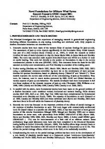
Our philosophy in designing materials is grounded in the philosophies of Simon and Taguchi. Because material systems are complex and prone to many of the sources of uncertainty discussed in Section II.B.1, we seek materials design solutions that are satisficing and robust. There are several categories of robust design, associated with different types of uncertainty. Type I robust design, originally proposed by Taguchi, centers on achieving insensitivity in performance with regard to noise factors—parameters that designers cannot control in a system. Relevant examples of noise factors are variation of ambient temperature, morphology changes, etc. Type II robust design, proposed by Chen and coauthors,37 relates to insensitivity of a design to variability or uncertainty associated with design variables—parameters that a designer can control in a system. A method for Types I and II robust design, namely, the Robust Concept Exploration Method37, has been proposed. The Robust Concept Exploration Method (RCEM) is a domain-independent approach for generating robust, multidisciplinary design solutions. Robust solutions to multi-functional design problems are preferable trade-offs between expected performance and sensitivity of performance due to deviations in design or uncontrollable variables. These solutions may not be absolute optima within the design space. As shown in Figure 9, RCEM is an integration of statistical experimentation and approximate models, robust design techniques, and multi-disciplinary design analyses and decisions. Given a set of design requirements, concept exploration starts with the classification of design variables, control factors, noise factors, and responses. Within the feasible range of the design space, the point generator module creates experimental points based on design of experiments techniques.
Figure 9. Computer Infrastructure of the RCEM. 37
12 American Institute of Aeronautics and Astronautics
The experimental points serve as input for simulation programs. The Experiments Analyzer inspects the experimental results and modifies the experimental design, as appropriate. The modification could be reducing or increasing the order of the response surface model, eliminating unimportant factors, reducing the design space to the region of interest, and planning additional experiments. After simulation, a response surface model is fit to the data and serves as a rapid evaluation tool for mapping design variables to approximations of performance mean and variance. In lieu of computationally expensive analysis codes, the response surface model is utilized for solving a compromise DSP. The compromise DSP is used as a mathematical model for incorporating multiple goals of bringing mean performance on target and minimizing deviations from nominal performance for multiple criteria. The compromise DSP is solved to determine robust top-level design specification for the system. The robust design methods discussed in the previous paragraphs are currently being extended for Types III and IV robust design. Type III robust design considers sensitivity to uncertainty embedded within a model (i.e., model parameter/structure uncertainty). Model parameter/structure uncertainty is typically different from the uncertainty associated with noise and control factors, because it could exist in the parameters or structure of constraints, metamodels, engineering equations, and associated simulation or analysis models. Our approach for Type III robust design is focused on incorporating the Error Margin Indices38 within the compromise DSP, and it is based on simultaneous incorporation of Type I, II, and III robust design techniques. Type III robust design is typically required to manage (a) inherent variability that is difficult or impossible to parameterize, (b) limited data, and (c) limited knowledge in a new domain such as materials design. Type IV robust design is focused on uncertainty associated with the design process. Design process uncertainty emanates from (a) changes in design specifications as a result of downstream or concurrent decisions and design activities or (b) the propagation and potential amplification of uncertainty due to the combined effect of analysis tasks performed in series or in parallel. Both sources of design process uncertainty are particularly common and important for multidisciplinary design and analysis—such as multifunctional, multi-scale materials design—with a plethora of shared or coupled variables and analyses performed on multiple length and time scales. Our approach to ensuring Type IV robustness is to pass ranged sets of design specifications, aimed at maintaining as much design freedom as possible, as long as possible. With respect to the design of a structural heat exchanger, this translates into passing the broadest range of design specifications from structural design to thermal design, or vice versa. Design specifications could include both coupled design variables and behavioral responses of one design stage that become input parameters for another design stage. Establishing a framework for all four types of robust design is quite challenging, but it is indispensable for an effective and efficient systems-based approach to multi-functional and multi-scale materials design, as envisioned here. C. Computing Infrastructure for a Systems-based Approach to Multi-Functional and Multi-Scale Materials Design In Sections II.A and II.B, we outlined our decision-centric approach for modeling design process and our robust design approach for exploring non-deterministic design spaces and solving decisions. In this section, we review our computing infrastructure for integrating heterogeneous software resources and facilitating on-line collaboration, information exchange, and utilization of software resources. Our approach is called X-DPR, 39,40 the extensible distributed product realization environment. It addresses the challenge of networking collaborating stakeholders with one another as well as with the myriad analysis codes and domain models that support their decisions, illustrated in the bottom of Figure 5. 1. eXtensible Distributed Product Realization Environment (X-DPR) X-DPR is a computer framework for integrating distributed software resources, referred to as agents, over the Internet. As used in this paper, the word ‘agents’ refers to software applications that provide some design-related services. Some examples of agents used for designing LCAs are thermal and structural analysis codes, robust design code, design of experiments and response surface modeling software. Other examples of agents include various materials databases, repositories of experimental data, and computational results from previous design scenarios. XDPR allows integration of all these heterogeneous software resources over the Internet to form a virtual materials design environment (see Figure 10). Through this virtual environment, distributed designers can collaborate to design new materials.
13 American Institute of Aeronautics and Astronautics
Databases
Simulation/Analysis Modules IUnknown
Material Experimental Properties Data
Computational Results
IUnknown
Thermal Analysis Models
Structural Analysis Models
IUnknown
Simulation X
DB X…
Design Exploration Software
F
i r e
w
a
l l
wall Fire
Design of Experiments
Meta Modeling
Exploration Algorithms
Software Level Digital Interfaces Virtual Material Design Space X-DPR Decision Level Digital Interfaces
Collaboration Between Teams Figure 10 – A Distributed Environment for Materials Design The architecture of the X-DPR framework is shown in Figure 11. The framework is designed based on peer-topeer communication between agents, in which each agent is an independent entity communicating with other agents. The agents require XML inputs and provide XML outputs. For example, in the structural design code, the input XML file contains information about the LCA geometry, boundary conditions, and meshing information. The output XML file contains information about peak stresses and deflection. XML is used for capturing information because it is a standard for representing information on the Internet. Each agent is associated with a WSDL (Web Service Description Language) file that aptly describes the functionality it provides. The WSDL file contains information about inputs and outputs of the agent. The information transfer between these software agents is through an XML based standard – SOAP (Simple Object Access Protocol). The SOAP standard forms a platform and language independent standard for information exchange between software applications. This enables agents to be developed in different languages and on different platforms. A client application (developed in Java) is used to model and execute a design process both automatically and remotely through the invocation of distributed agents. The four main elements of the client application are (1) a process diagram tool, (2) an interface mapping tool, (3) a data visualization tool and (4) a dynamic user interface generation tool. The process diagram tool contains a “white board” on which a process diagram may be created using simple drag and drop utilities. For example, the process for designing LCAs shown in Figure 5 can be modeled graphically in the process diagram tool. The phases, events and tasks that lie at the center of our modeling approach, discussed in Section II.A are connected to indicate the flow of information between these entities. The tool equips designers with the ability to search for suitable agents and assign tasks to these agents by interacting with and executing remote agents. The interface-mapping tool is developed to provide seamless flow of information between agents. In a generic framework, it is very likely that the output of one agent may not be identical to the required input of another agent. For example, the outputs of the Design of Experiments may not be the same as inputs to structural and thermal analysis codes. In such a scenario, it is difficult to establish structural compatibility of information between the inputs and outputs of agents. The interface-mapping tool provides a means of mapping information between the XML-based interfaces of agents. The data visualization tool on the other hand provides a means for viewing the information contained in XML files. Since the data exchanged in X-DPR is in the XML format, it is inconvenient to view the data directly from XML files containing it. The data visualization tool thus
14 American Institute of Aeronautics and Astronautics
provides a user interface for easier interpretation of the data. Finally, the dynamic user interface generation tool facilitates remote user interactions with agents. An agent describes user interface elements according to the manner in which stakeholders interact with them. Based on this description, a user interface is generated dynamically at the client side, and required information is obtained. The input obtained from the user is then sent back to the agent for processing. This increases the modularity of the framework by separating the actual engineering information from the user interface used to manipulate it. The framework also contains a search service that is used to locate required agents. This service maintains a database of WSDL files for all available agents. When a user enters a search string, a keyword query is generated that locates related agents that may be selected by a user. Having discussed the general software framework for distributed design of materials, we now move on to information modeling for design of materials. These information models facilitate capturing, reusing and archiving complex information.
Agent A
Input
Output
Output
Input
Agent B
XMLMapping Application
Agent C
Output
Input
Input
Output
Agent D
Interface Mapping Tool
Process Diagram Tool
ute ec Ex
Dynamic UI Generation Tool
Data Visualization Tool
XML XML Search Service
WSDL
SOAP
WSDL
XML
XML
Archive
Archive Data
Figure 11 – Architecture of X-DPR Framework 2. Materials Information Modeling One of the key prerequisites for design in a multi-team environment is to develop a consistent and standardized way of representing information that can be used by all stakeholders involved in the process. Currently, there is no comprehensive information model for representing the complex information of multifunctional materials. The various complexities in the required information arise from the need to represent and integrate structures and properties at the macro, meso, micro and quantum levels, as indicated in Figure 4. With respect to designing the structural heat exchanger, only the Continuum PDE and Reduced Order Model Levels of Figure 6 are considered. Another source of complexity is the various types of information associated with multifunctional, multi-scale materials design, such as scalars, matrices, tensors, images, graphs, mathematical equations, computer programs, etc. In order to address these challenges, we propose an information model based on existing ISO standards developed at NIST; specifically, extending the STEP standard. Although STEP standards are well developed for representing data in the latter stages of design, these should be extended to represent material data with robust design considerations throughout the design process. For modeling, we will use the Express41 modeling language that supports object oriented modeling and is developed specifically for complex engineering data. This information model will subsequently be instantiated in the form of a database in order to support archival and reuse of information. This database will then be used as a foundation to develop Application Programming Interfaces (APIs) for accessing the information remotely over the Internet. The database and APIs will serve to enable distributed stakeholders as well as software applications/agents to interact with the material information in a consistent manner. Through the formalization of the underlying information model, standardized digital interfaces at the computing level can be identified between teams of designers. The information model is the key for capturing, archiving, 15 American Institute of Aeronautics and Astronautics
translating and retrieving information from the corresponding database. This material information model is a fundamental and essential starting point for moving towards a future STEP standard that will accelerate development of commercial software applications for materials modeling. A further advantage of developing an information model based on existing STEP standards is the possibility of extending existing CAD applications to include material design considerations.
III.
Closure
In order to support multi-functional, multi-scale materials design, a systems-based design approach is required. Without such an approach in which to embed performance-property-structure-processing relations, manage information flow, interrogate models, explore variability, and engage decision-support protocols to facilitate choosing among alternatives, materials design may continue to be more of an art than a science. Although the approach presented in this paper comprises a significant initial step towards systematic materials design, many open research issues remain. For example, there are many open questions regarding materials design process modeling. Some of the questions we are asking include: How should information transformations (i.e., decisions and supporting tasks) be sequenced so that overarching systems objectives are satisfied more easily, robustness is achieved, and flexibility retained? How can both the product being designed and the process used to design it be adapted in order to accommodate changes in stakeholder objectives and or resources? How can the effect of new technologies be evaluated with respect to their influence on system performance and increases in design freedom? How can the modularity of decisions and their components be improved so that system level integration and adaptation is facilitated, especially in the context of complex, dynamic design chains? How can the effect of changing the order and or influence of different decision-makers on the product with regard to quality and robustness be predicted? Open questions regarding distributed design of materials include: How can different fidelities of models be captured in a repository of models? How can assumptions associated with different models be captured in a semantically rich manner? How can information about materials at various levels of abstraction with couplings and interdependencies be captured? How can huge amounts of materials data be organized to facilitate efficient search and retrieval? How can computationally expensive runs be made more efficient by using grid-computing technologies? A number of challenges remain for establishing a comprehensive robust design approach for materials design and other applications. One of the remaining challenges involves incorporating highly expensive experiments and computational analyses, from which only a few data points can be obtained. This is still a major source of uncertainty in materials design, and it is still difficult to address it with robust design techniques. Another challenge involves estimating and reducing model structure uncertainty for Type III robust design. Model structure uncertainty is one of the most prevalent sources of uncertainty in materials design because most models are based on extensive assumptions and idealizations. To date, methods for managing model structure uncertainty have not been studied extensively. A comprehensive robust design method is needed that integrates all four types of robust design discussed in Section II.B. Finally, efficient computational techniques and search algorithms are needed for obtaining robust, ranged sets of design specifications. Traditional optimization methods provide only point solutions, and many random search methods—such as Monte Carlo analysis—are extremely computationally expensive, especially for systems with large numbers of variables and/or computationally expensive analysis models. Finally, it is important to test, expand, and improve a systems-based approach for materials design by applying it to materials design problems of increasing complexity. Currently, we are participating in an AFOSR-funded MURI project (AFOSR 1606U81) for investigating nano-structured, multifunctional, energetic, structural materials to be incorporated into applications such as Target Penetrating Missiles (TPM). The principal focus of the MURI is to develop robust strategies and implementations for integrating physically-based modeling with engineering systems design methods for designing the micro- or meso-structure of materials to deliver multiple functions. This materials design activity requires enhanced understanding and simulation of material process-structure-property relations, characterized by a hierarchy of length and time scales. Relevant perspectives range from quantum mechanics and molecular dynamics to continuum mechanics and reduced order models, with distinct teams of experts working on modeling relevant material structure-property relations. Information and expertise from experiments and modeling reside with experts located in distributed locations. Consequently, the nature of information that must be passed across levels of the modeling hierarchy and among a distributed network of specialists is both quantitative and qualitative. We are utilizing and refining the systems-based approach presented in this paper for this and other challenging materials design applications. 16 American Institute of Aeronautics and Astronautics
Establishing systems-based materials design methods is an important step towards enabling rapid, concurrent design of products and materials with the potential for significant technological innovations. To make this happen, the materials design community must reduce cycle times for the development of new materials, bringing them in line with continuously falling product development cycle times. Certainly, increasing computational power and a rapidly expanding stock of physics-based models of material process-structure-property relations are critical factors for addressing this challenge. In fact, one of the grand challenges at the intersection of engineering, materials science, materials physics and computation is the development of a quantitative understanding of the relation of material properties to material structure at various length scales. However, we argue that a primary raison d'être for these materials science concepts and tools is to support systems-based materials design methodologies that can be used to improve products and processes by informed designers. Accordingly, our primary goal for the near future is to establish the intellectual and computing foundations needed to support a team of designers engaged in simulationbased, integrated, robust design of products and materials. The foundations introduced in this paper are only the beginning.
Appendix An Illustrative Example of Multifunctional Cellular Materials Design for a Structural Heat Exchanger Application Linear cellular alloys (LCAs) are ordered, metallic cellular or honeycomb materials with extended prismatic cells, as illustrated in Figure 12. LCAs or prismatic cellular materials are well-suited for multifunctional applications in which the material is required to meet multiple performance objectives. Prismatic cellular materials have a combination of properties that make them suitable for a range of multifunctional applications such as ultralight structures, heat exchangers, fuel cell and battery subsystems, energy absorption systems, and others.42-44 A newly developed, flexible manufacturing process Figure 12 – Ordered, Prismatic Cellular Materials enables extensive tailoring of prismatic cellular materials for these multifunctional applications. Via a thermo-chemical extrusion fabrication process developed at Georgia Tech, LCAs or prismatic cellular materials can be produced with nearly arbitrary two-dimensional topologies and dimensions, metallic base materials, and wall thicknesses as small as 50 µm.45 In the fabrication process, metal oxide powder-based slurries are extruded through a customized die (that facilitates in-plane topological and dimensional tailoring of the cellular material), reduced in a hydrogen environment, and then sintered at high temperature to form metallic cellular structures. Several base materials have been successfully processed, including steels, Nickel-based alloys, and copper. Due to the extensive freedom afforded by the fabrication process for tailoring the two-dimensional topologies and dimensions of cells and cell walls, a rich array of materials design possibilities are available, providing a host of challenges for designing these materials for multifunctional applications that require compromises between disparate goals and objectives. In the present example, we design prismatic cellular materials for a structural heat exchanger application in which the cellular material is expected to dissipate heat via conduction and convection and to support structural loads. The example is abstracted from potential applications such as actively cooled skins in high performance aerospace vehicles or combustor liners in gas turbine engines. Our goal for the present example is to determine appropriate cell aspect ratios and sizes to achieve functional goals for objectives from two distinct physical domains: (1) overall rate of steady state heat transfer, Qtotal, and (2) overall structural elastic stiffness in the x- and ydirections, Ex/Es and Ex/Es, respectively (normalized by the solid modulus, Es, of the base material in the cell walls).
17 American Institute of Aeronautics and Astronautics
The device illustrated in Figure 13 is a sample structural heat exchanger, comprised of a prismatic cellular material or LCA. It has fixed overall width (W), depth (D), and height (H) of 25 mm, 75 mm, and 25 mm, respectively. It is insulated on the left, right, and bottom sides and is subjected to a heat source at constant temperature, Ts, on the top face. The mechanism for heat dissipation is forced convection via air with entry temperature, Tin,
& . The flow rate is and total mass flow rate, M
Ts
Heat Source and/or Uniformly Distributed Load
z x
tV
y
h1
H
h2 . . .
h Nv
tH
D
variable, but it is linked to the available pressure w1 w2 w3 . . . w NH head through a representative characteristic fan W curve. Steady state, incompressible laminar Air Flow, T in flow is assumed. The solid material in the Figure 13 - Compact, Forced Convection Heat Exchanger device is copper. The thermal conductivity, ks, with Graded, Rectangular, Prismatic, Cellular Materials of copper samples fabricated with the thermochemical extrusion process has been measured to be 363 W/m-K (Ref. 46). For this example, the prismatic cellular structure is comprised exclusively of rectangular cells, but the size, shape (i.e., aspect ratio), and number of cells are permitted to vary in a graded manner. In a graded structure, each row of cells may assume a different height, hi, and each column a different width, wi, as illustrated in Figure 13. The only restriction on cell height and width is that the cells must fit within the external dimensions with sufficient remaining space for vertical cell walls of variable thickness, tV, and horizontal walls of variable thickness, tH. The numbers of cells in the horizontal and vertical directions are designated NH and NV, respectively.
Acknowledgements Carolyn Conner Seepersad is supported by a Hertz Fellowship from the Fannie and John Hertz Foundation. Marco Gero Fernández is sponsored by a National Science Foundation IGERT Fellowship through the TI:GER Program at the Georgia Tech College of Management and a President’s Fellowship from the Georgia Institute of Technology. We gratefully acknowledge support from National Science Foundation grants DMI-0085136 and DMI0100123 and Air Force Office of Scientific Research grant F49620-03-1-0348.
References 1 McDowell, D. L.,1998, New Directions in Materials Design Science and Engineering (MDS&E). Georgia Institute of Technology and Morehouse College, Atlanta, GA, Sponsored by the U.S. National Science Foundation. 2 Olson, G. B., 2000, “Designing a New Material World,” Science, Vol. 288, No. 5468, pp. 993-998. 3 Ashby, M. F., 1999, Materials Selection in Mechanical Design, Butterworth-Heinemann, Oxford, UK. 4 Olson, G. B., 1997, “Computational Design of Hierarchically Structured Materials,” Science, Vol. 277, No. 5330, pp. 12371242. 5 Muster, D. and F. Mistree, 1988, “The Decision Support Problem Technique in Engineering Design,” International Journal of Applied Engineering Education, Vol. 4, No. 1, pp. 23-33. 6 Mistree, F., D. Muster, J. A. Shupe and J. K. Allen, 1989, "A Decision-Based Perspective for the Design of Methods for Systems Design," Recent Experiences in Multidisciplinary Analysis and Optimization, Hampton, Virginia. Paper Number: NASA CP 3031. 7 Mistree, F., W. F. Smith, B. Bras, J. K. Allen and D. Muster, 1990, "Decision-Based Design: A Contemporary Paradigm for Ship Design," Transactions, Society of Naval Architects and Marine Engineers, Jersey City, New Jersey, Vol. 98, pp. 565597. 8 Mistree, F., W. F. Smith, S. Z. Kamal and B. A. Bras, 1991, "Designing Decisions: Axioms, Models and Marine Applications," Fourth International Marine Systems Design Conference, Kobe, Japan, Society of Naval Architects of Japan, pp. 1-24.
18 American Institute of Aeronautics and Astronautics
9 Mistree, F., W. F. Smith and B. A. Bras, 1993, "A Decision-Based Approach to Concurrent Engineering," Handbook of Concurrent Engineering (H. R. Paresai and W. Sullivan, Eds.), Chapman & Hall, New York, pp. 127-158. 10 Mistree, F., B. A. Bras, W. F. Smith and J. K. Allen, 1996, “Modeling Design Processes: A Conceptual, Decision-Based Perspective,” International Journal of Engineering Design and Automation, Vol. 1, No. 4, pp. 209-221. 11 Bras, B. A. and F. Mistree, 1991, "Designing Design Processes in Decision-Based Concurrent Engineering," SAE Transactions, Journal of Materials & Manufacturing (SAE Paper 912209), SAE International, Warrendale, Pennsylvania, Vol. 100, pp. 451-458. 12 Mistree, F., O. F. Hughes and B. A. Bras, 1993, "The Compromise Decision Support Problem and the Adaptive Linear Programming Algorithm," Structural Optimization: Status and Promise (M. P. Kamat, Ed.), AIAA, Washington, D.C., pp. 247286. 13 Mistree, F., K. Lewis and L. Stonis, 1994, "Selection in the Conceptual Design of Aircraft," 5th AIAA/USAF/NASA/ISSMO Symposium on Recent Advances in Multidisciplinary Analysis and Optimization, Panama City, FL, pp. 1153-1166 14 Fernández, M. G., C. C. Seepersad, D. W. Rosen, J. K. Allen and F. Mistree, 2001, "Utility-Based Decision, Support for Selection in Engineering Design," 13th Internation Conference on Design Theory and Methodology, Pittsburgh, Pennsylvania. Paper Number: DETC2001/DAC-21106. 15 Seepersad, C. C., F. Mistree and J. K. Allen, 2002, "A Quantitative Approach for Designing Multiple Product Platforms for an Evolving Portfolio of Products," ASME Design Engineering Technical Conferences, Advances in Design Automation, Montreal, Canada. Paper Number: DETC2002/DAC-34096. 16 Integrated Definition for Functional Modeling (IDEF 0), 1993, Federal Information Processing Standards Publication 183. 17 Eppinger, S., D. E. Whitney, R. P. Smith and D. A. Gebala, 1994, “A Model-based Method for Organizing Tasks in Product Development,” Research in Engineering Design, Vol. 6, No. 1, pp. 1-13. 18 Shimomura, Y., M. Yoshioka, H. Takeda, Y. Umeda and T. Tomiyama, 1998, “Representation of Design Object Based on the Functional Evolution Process Model,” Journal of Mechanical Design, Vol. 120, No. 2, pp. 221-229. 19 Ullman, D. G., 1992, “A Taxonomy for Mechanical Design,” Research in Engineering Design, Vol. 3, No. 3, pp. 179-189. 20 Maher, M. L.,1990, "Process Models for Design Synthesis," AI Magazine, Winter 1990, pp. 49-58. 21 Maimon, O. and D. Braha, 1996, “On the Complexity of the Design Synthesis Problem,” IEEE Transactions on Systems, Man, and Cybernetics - Part A: Systems and Humans, Vol. 26, No. 1, pp. 142-151. 22 Panchal, J. H., M. G. Fernández, C. J. J. Paredis and F. Mistree, 2004, "Template-based Design Process Modeling," 10th AIAA/ISSMO Multidisciplinary Analysis and Optimization Conference, Albany, New York. Paper Number: AIAA-2004-4601. 23 Gerhard, F. J., D. W. Rosen, J. Allen and F. Mistree, 2000, "A Distributed Product Realization Environment for Design and Manufacturing," ASME Computers and Information in Engineering Conference, Baltimore, Maryland. Paper Number: DETC2000/CIE-14624. 24 Gerhard, J. F., S. J. Duncan, Y. Chen, J. K. Allen, D. W. Rosen and F. Mistree, 1999, "Towards a Decision-Based, Distributed Product Realization Environment for Engineering Systems," ASME Computers and Information in Engineering Conference, Las Vegas, Nevada. Paper Number: DETC1999/CIE-9085. 25 Xiao, A. H., R. Kulkarni, J. Allen, D. W. Rosen, F. Mistree and S. C. Feng, 2001, "A Web Based Distributed Product Realization Environment," ASME Computers and Information in Engineering Conference, Pittsburgh, Pennsylvania. Paper No: DETC2001/CIE-21766. 26 Hernandez, G. and F. Mistree, 2000, “Integrating Product Design and Manufacturing: A Game Theoretic Approach,” Engineering Optimization, Vol. 32, No. 6, pp. 749-775. 27 Marston, M. and F. Mistree, 2000, "Game-Based Design: A Game Theoretic Extension to Decision-Based Design," ASME Design Theory and Methodology Conference, Baltimore, Maryland. Paper Number: DETC2000/DTM-14578 28 Hacker, K. and K. Lewis, 1998, "Using Robust Design Techniques to Model the Effects of Multiple Decision-Makers in a Design Process," 1998 ASME Design Engineering Technical Conferences, Atlanta, Georgia. Paper Number: DETC98/DAC5604. 29 Kalsi, M., K. Hacker and K. Lewis, 1999, "A Comprehensive Robust Design Approach for Decision Trade-Offs in Complex Systems," 1999 ASME Design Engineering Technical Conferences, Las Vegas, Nevada. Paper Number: DETC99/DAC-8589. 30 Xiao, A., S. Zeng, J. Allen, F. Mistree and D. W. Rosen, 2002, "Collaborating Multidisciplinary Decision Making Using Game Theory and Design Capability Indices," 9th AIAA/ISSMO Symposium on Multidisciplinary Analysis and Optimization, Atlanta, Georgia. Paper No: AIAA 2002-5617. 31 Fernandez, M. G., D. W. Rosen, J. Allen and F. Mistree, 2002, "Digital Interfaces: The Key to Effective Decision-Making in Collaborative Design and Manufactuting," ASME Computers and Information in Engineering Conference, Montreal, Canada. Paper Number: DETC2002/CIE-34466. 32 Fernandez, M. G., D. W. Rosen, J. Allen and F. Mistree, 2002, "On a Decision Support Framework for Distributed Collaborative Design and Manufacture," 9th AIAA/ISSMO Symposium on Multidisciplinary Analysis and Optimization, Atlanta, Georgia. Paper Number: AIAA2002-5496. 33 Panchal, J. H., M. G. Fernández, C. J. J. Paredis, J. K. Allen and F. Mistree, 2004, "Designing Design Processes in Product Lifecycle Management: Research Issues and Strategies," ASME Computers and Information in Engineering Conference, Salt Lake City, Utah. Paper Number: DETC2004/CIE-57742. 34 Isukapalli, S. S., A. Roy and P. G. Georgopoulos, 1998, “Stochastic Response Surface Methods (SRSMs) for Uncertainty Propagation: Application to Environmental and Biological Systems,” Risk Analysis, Vol. 18, No. 3, pp. 351-363.
19 American Institute of Aeronautics and Astronautics
35 Taguchi, G., 1993, Taguchi on Robust Technology Development: Bringing Quality Engineering Upstream, ASME Press, New York. 36 Simon, H. A., 1982, The Sciences of the Artificial, The MIT Press, Cambridge, Mass. 37 Chen, W., 1995, "A Robust Concept Exploration Method for Configuring Complex Systems," Ph.D. Dissertation, School of Mechanical Engineering, Georgia Institute of Technology, Atlanta, Georgia, 38 Choi, H.-J., R. Austin, J. K. Allen, D. L. McDowell and F. Mistree, 2003, "An Approach for Robust Micro-Scale Materials Design under Unparameterizable Variability," 10th AIAA/ISSMO Multidisciplinary Analysis and Optimization Conference, Albany, New York. Paper Number: AIAA2004-4331. 39 Panchal, J. H., M. Chamberlain, D. W. Rosen, J. Allen and F. Mistree, 2002, "A Service Based Architecture for Information and Asset Utilization in Distributed Product Realization," 9th AIAA/ISSMO Symposium on Multidisciplinary Analysis and Optimization, Atlanta, Georgia. Paper Number: AIAA-2002-5480. 40 Choi, H.-J., J. H. Panchal, D. W. Rosen, J. K. Allen and F. Mistree, 2003, "Towards a Standardized Engineering Framework for Distributed Collaborative Product Realization," ASME Computers and Information in Engineering Conference, Chicago, Illinois. Paper Number: DETC2003/CIE-48279. 41 Schenck, D. A. and P. R. Wilson, 1994, Information Modeling: The EXPRESS Way, Oxford University Press. 42 Gibson, L. J. and M. F. Ashby, 1997, Cellular Solids: Structure and Properties, Cambridge University Press, Cambridge, UK. 43 Evans, A. G., J. W. Hutchinson, N. A. Fleck, M. F. Ashby and H. N. G. Wadley, 2001, “The Topological Design of Multifunctional Cellular Materials,” Progress in Materials Science, Vol. 46, No. 3-4, pp. 309-327. 44 Hayes, A. M., A. Wang, B. M. Dempsey and D. L. McDowell, 2004, “Mechanics of Linear Cellular Alloys,” Mechanics of Materials, in press. 45 Cochran, J. K., K. J. Lee, D. L. McDowell and T. H. Sanders, 2000, "Low Density Monolithic Honeycombs by Thermal Chemical Processing," Proceedings of the 4th Conference on Aerospace Materials, Processes, and Environmental Technology, Huntsville, AL 46 Church, B. C., B. M. Dempsey, J. L. Clark, T. H. Sanders and J. K. Cochran, 2001, "Copper Alloys from Oxide Reduction for High Conductivity Applications," Proceedings of IMECE 2001, International Mechanical Engineering Congress and Exposition, New York
20 American Institute of Aeronautics and Astronautics