FPGA-BASED VECTOR PROCESSOR FOR. ALGEBRAIC EQUATION SOLVERS
*. Hongyan Yang and Sotirios G. Ziavras. New Jersey Institute of Technology.
FPGA - BASED VECTOR PROCESSOR FOR ALGEBRAIC EQUATION SOLVERS ⋆ Hongyan Yang and Sotirios G. Ziavras New Jersey Institute of Technology Department of Electrical and Computer Engineering University Heights, Newark, NJ 07102 Email: {hy34, ziavras}@njit.edu
Scalar Data Bus
A BSTRACT In this paper, a vector unit tightly coupled with a five-stage pipelined scalar processor is designed and implemented on an FPGA platform. This system supports IEEE 754 single-precision floating-point calculations and sparse matrix operations. The W-matrix linear equation solution method for sparse systems is run on this vector processor. The obtained performance demonstrates that large linear algebraic equations, a great challenge to general-purpose processors, can be solved efficiently on our vector processor.
Vector Unit
text text text text text
text FPUtext Add Units
text text text
text Data text text text Memory Banks
text text text
text FPU text text text Multiply Units
Scalar CPU
Figure 1.
⋆ This work was supported in part by the U.S. Dept. of Energy under grant DE-FG02-03CH11171.
text Vector text text text Register File
VLR VMR
I. I NTRODUCTION There have been significant FPGA advances in logic density, speed and architecture in the last decade; SOPC (System-On-a-Programmable-Chip) designs with FPGAs have recently become realizable. Moreover, their flexibility, fast development cycles and low cost render FPGA-based SOPC systems attractive for computationintensive tasks. SPLASH 2, ArMen, SPISM-I and DECPeRLe-1 are older FPGA-based systems that demonstrated benefits for various applications [1]. Vector processors were originally introduced for supercomputers applied to scientific and engineering computing; they apply the same operation simultaneously to multiple array elements. So matrix operations can be readily mapped to vector instructions [2, 3]. By exploiting fine-grain parallelism and data locality, a vector processor is more effective on matrix operations than traditional superscalars, very long instruction word (VLIW) processors or multithreaded architectures [4]. In this paper, a vector microprocessor is designed and implemented on an FPGA platform. The W-matrix method, which was proposed for power flow analysis problems [5, 6], is an efficient solution method for sparse linear equations because of its inherent parallelism; it can also be mapped effectively to a vector processor. In this paper, several real power network matrices are used to solve linear equations on our
Vector Mem Unit (VMU)
text text text
256*32 bits Instruction cache
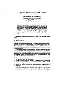
Block diagram of the vector processor
FPGA-based system and the execution time is analyzed to demonstrate high performance. II. V ECTOR P ROCESSOR D ESIGN
AND
I MPLE -
MENTATION
Our vector processor, as shown in Fig. 1, is composed of a five-stage pipelined scalar processor and a vector core. The scalar processor fetches and decodes instructions. It does the actual work for scalar commands and forwards vector instructions to the vector core. The vector core contains the vector register file, vector memory unit (VMU), eight floating-point adders, eight floating-point multipliers and the instrucFPU adder
FPU adder
FPU adder
FPU adder
FPU adder
FPU adder
FPU adder
FPU adder
bank0
bank1
bank2
bank3
bank4
bank5
bank6
bank7
V0(0)
V0(1)
V0(2)
V0(3)
V0(4)
V0(5)
V0(6)
V0(7)
V0(8)
V0(9)
V0(10)
V0(11)
V0(12)
V0(13)
V0(14)
V0(15)
...
...
...
...
...
...
...
...
V7(0)
V7(1)
V7(2)
V7(3)
V7(4)
V7(5)
V7(6)
V7(7)
V7(8)
V7(9)
V7(10)
V7(11)
V7(12)
V7(13)
V7(14)
V7(15)
FPU Multiplier
FPU Multiplier
FPU Multiplier
FPU Multiplier
FPU Multiplier
FPU Multiplier
FPU Multiplier
FPU Multiplier
Figure 2.
Vector register file organization
Table I.
Execution Times (NNZs: number of non-zeros in the matrix, LU: LU factorization)
Matrix size Original NNZs NNZs after LU NNZs in W-matrix Clock cycles Execution time(us)
20 × 20 24 42 52 2562 50.235
39 × 39 46 65 95 3794 74.392
tion cache; it interfaces eight banks of data memory. Communication between the vector processor and the host is done through the on-chip dual-port memory. The vector register file contains eight vector registers; each has sixteen 32-bit elements. Increasing the number of vector registers can provide more storage space for intermediate values, thus reducing the memory bandwidth requirements by allowing more operand reuse. However, for the matrix operations considered in this paper, data is not reused; in addition, this size for vector registers can still show the effectiveness of our design. However, in future work the number of vector register elements may be increased from 16 to 32, or 64 for even larger matrices. More vector elements can amortize the startup time and speedup the overall execution. To explore vector element parallelism, the vector registers are interleaved across multiple memory banks and calculation units, as shown in Fig. 2; each bank provides five read ports and three write ports, and these ports are connected to the adder, multiplier and VMU. The VMU controls all the data transfers to and from the data memory banks. It supports scalar load/store, vector load/store and also indexed load/store for sparse matrices. The execution time for indexed load/store is not static because different data storage patterns in the eight data memory banks may result in different contention patterns. In our implementation, an ad hoc circuit is included to guarantee that the indexed load/store finishes in the shortest time. In addition, floating-point IP (Intellectual Property) FPGA cores purchased from Quixilica are used to implement the floating-point adders and multipliers. Our vector processor is embedded in one of the two Xilinx XC2V6000 FPGA chips on the Annapolis Micro Systems WILDSTAR-II board [7]. In our implementation, the processor occupies 14,842 slices on the chip, which is equivalent to 1.652 million system gates in ASIC design. The speed level of our XC2V6000 chip is -5 and the vector processor can run at 51MHz. All these numbers are obtained after the place and route phase of the implementation. Although the frequency is limited by current FPGA structure and technology features, the vector system still provides a high-performance platform because it has a simplified instruction set, abundance in calculation units, tightly coupled memory and a well-defined data storage scheme. With ever improving FPGA technology, even higher performance of this vector implementation on FPGA-based SOPC
49 × 49 59 80 106 3573 70.059
118 × 118 179 263 407 9168 179.764
274 × 274 669 1066 1567 35664 699.294
platforms should be guaranteed in the future. III. P ERFORMANCE R ESULTS AND C ONCLUSIONS To test the performance of the proposed vector system, the W-matrix method was implemented. By employing the W-matrix method, the problem of solving sparse linear equations can be turned into several steps of matrix multiplication. Further, in each step calculations can be executed in parallel [5, 6]. Thus, the W-matrix method can yield better performance on SIMD, MIMD or vector processors than the sequential substitution scheme in the conventional approach. For the sake of brevity, we do not present here the details of the W-matrix method. Several linear equations represented by sparse matrices for real power networks were solved on our vector processor. The execution times on the FPGA platform are shown in Table I. It can be concluded that the execution time for solving linear equations with matrices of size up to 274 × 274 is less than a millisecond despite the 51MHz low frequency of the FPGA. More recent FPGAs, could improve the performance even further. R EFERENCES [1] B. Radunovic, “An overview of advances in reconfigurable computing systems.” Hawaii International Conference on System Sciences, 1999. [2] J. Wawrzynek, K. Asanovic, B. Kingsbury, D. Johnson, J. Beck, and N. Morgan, “Spert-II: A vector microprocessor system,” IEEE Computer, vol. 29, no. 3, pp. 79–86, 1996. [3] D. A. Patterson and J. L. Hennessy, Computer Architecture: A Quantitative Approach, 3rd ed. San Mateo: Morgan Kaufmann, 2002. [4] R. Krashinsky, C. Batten, S. Gerding, M. Hampton, B. Pharris, J. Casper, and K. Asanovi´c, “The vector-thread architecture,” in 31st International Symposium on Computer Architecture, Munich, Germany, June 2004. [5] F. L. Alvarado, D. C. Yu, and R. Betancourt, “Partitioned sparse A−1 methods,” IEEE Trans. Power Syst., vol. 5, no. 2, pp. 452– 459, May 1990. [6] M. K. Enns, W. F. Tinney, and F. L. Alvarado, “Sparse matrix inverse factors,” IEEE Trans. Power Syst., vol. 5, no. 2, pp. 466– 473, May 1990. [7] The Wildstar II datasheet. http://www.annapmicro.com