2009 17th IEEE Symposium on Field Programmable Custom Computing Machines
FPGA Implementation of a Single-Precision Floating-Point MultiplyAccumulator with Single-Cycle Accumulation Arun Paidimarri Indian Institute of Technology, Bombay
[email protected]
Alessandro Cevrero, Philip Brisk, Paolo Ienne École Polytechnique Fédérale de Lausanne
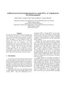
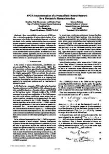
[email protected] The FPMAC, shown in Fig. 1, has 11 pipeline stages. The notable features of this architecture are the “Base-32” conversion and de-conversion (Stages 6 and 11) and the accumulator (Stage 8). The 48-bit mantissa multiplier outputs produced in Stage 5, and retained in carry-save form, are converted to a non-traditional FP representation shown in Fig. 2.1 The mantissa is truncated to 24 bits, 22 to the right of the decimal point and 2 to the left. The truncated mantissas are shifted left, as specified by the 5 least significant bits of the exponent, expanding them from 24 to 55 bits: 33 bits to the left of the decimal and 22 bits to the right. Afterwards, only the three most significant bits of the exponent are needed. The value of the FP number in this format is (-1)sign × f* × 2(32 × exp*), where f* is the shifted mantissa and exp* is the truncated exponent. The accumulator, shown in Fig. 3 and Table I, is the critical path. The Base-32 representation eliminates shifters used for mantissa alignment, which are replaced with less costly conditional constant shifters. The outputs of the sign inversion stage are the incoming exponent (E7) and mantissa (C7 and S7). The accumulated result is a feedback exponent (E8) and mantissa (C8 and S8). The updated exponent and mantissa are also stored to E8, C8 and S8. The incoming and feedback mantissas are shifted by the difference between the incoming and feedback exponents. The exponents must be equalized before mantissa addition. The Base-32 representation ensures that all shifts are by 0 or 32 bits. Four cases are computed in parallel. Table I lists the conditions that resolve the paths. Fig. 4 shows that two 4:2 compressors can map onto three Adaptive Logic Modules (ALMs), the logic cell used in Altera’s Stratix II-IV FPGAs.
Abstract This paper describes an FPGA implementation of a single-precision floating-point multiply-accumulator (FPMAC) that supports single-cycle accumulation while maintaining high clock frequencies. A nontraditional internal representation reduces the cost of mantissa alignment within the accumulator. The FPMAC is evaluated on an Altera Stratix III FPGA.
1. Introduction This paper describes an FPGA implementation of a single-precision floating-point multiply-accumulator (FPMAC), originally designed by Intel [1]. Singlecycle accumulation with minimal frequency degradation is achieved by using a non-traditional internal FP representation that sacrifices IEEE compliance in its exception handling, rounding, and detection of overflow. The accumulator retains the result in carry-save form without normalization or rounding. The FPMAC is evaluated on an Altera Stratix III FPGA.
2. FPMAC Architecture An IEEE-754 single-precision (32-bit) FP number has three fields—a sign bit, an 8-bit biased exponent, and a 23-bit fraction called a mantissa. We assume that the reader is familiar with the IEEE standard for floating-point numbers. The FPMAC does not support denormalized numbers, infinity, or not-a-number (NaN). If f is the mantissa and exp is the biased exponent; the value of an IEEE-754 compliant FP number is (-1)sign × (1.f) × 2exp. The 1 is not represented in the format, but exists internally in the FPMAC’s computation logic. Thus, the bitwidth of the mantissa within the FPMAC is actually 24 bits.
978-0-7695-3716-0/09 $25.00 © 2009 IEEE DOI 10.1109/FCCM.2009.50
1
Intel [1] refers to this non-traditional FP format as “Base-32”. This name is somewhat misleading, as it should indicate that the base of the exponentiation in the non-traditional format is 232, while the 3-bit exponent remains in radix-2. To avoid confusion between the two papers, we retain Intel’s nomenclature.
267
Authorized licensed use limited to: EPFL LAUSANNE. Downloaded on April 08,2010 at 09:25:53 UTC from IEEE Xplore. Restrictions apply.
SA
EA
MA
SB
EB
Path C: The accumulated result is never explicitly normalized. If the number of leading zeroes or ones in S8 + C8 exceeds 31, then S8 and C8 are shifted left by 32 bits. If E8 = E7 + 2, S7 and C7 are shifted right by 32 bits as well, and E7 is adjusted accordingly. A 4:2 compressor adds the result, which is shifted right (along with an appropriate exponent adjustment) if there is an overflow.
MB
1 Sign Control
Product Product Encoding
EA + EB - Bias
Compressor Tree 1
2 Compressor Tree
Compressor Tree 2
3
Compressor Tree 3
4
Compressor Tree 4
5
Base-32 Conversion
Exp. Control
6
Shift
3:2
Sign Inversion
Critical Path
4:2 Exp. Compare
9
Final Adder
LZA
Normalize
Base 2 Conversion
SB
Paths A and C of the accumulator are critical, requiring 6 layers of 6-LUTs. The paths through the leading zero anticipator (LZA) and the zero detector, in contrast, require 5 layers of ALMs. One ALM can be removed from the delay of Paths A and C by dividing the datapath, as shown in Fig. 5 for Path A. In Fig. 3(a), there are three combinations of shifts on the inputs to the 4:2 compressors; all shifts are conditional 32-bit right shifts. The three cases are: (1) no shifting; (2) shift (S7, C7), but not (S8, C8); and (3) shift (S8, C8) but not (S7, C7). All three combinations are enumerated in Fig. 5, and the result is added by three 4:2 compressors in parallel, and a 3:1 multiplexor selects the result. Overflow detection and conditional shifting of the mantissa is applied to the multiplexor output. This design removes the 3-bit comparator from the critical path. Replacing the conditional shifter (a 2:1 multiplexor) on each path is offset by the introduction of the 3:1 multiplexor; the benefit comes from resolving the conditional shifting after the 4:2 compressors. The 3-bit comparison can be performed in parallel with the 4:2 compressors, eliminating their dependence in Fig. 3(a). The 3-bit comparator now computes the two multiplexor control signals, rather than the 3 output bits shown in Fig. 3(b).
7
8 Single-cycle Accumulate
Path D: If S8 + C8 = 0, the result is the incoming mantissa, S7, C7, i.e., E8 = E7, S8 = S7, and C8 = C7. This case is handled separately to handle mismatches between the incoming and feedback exponents.
EB
Shift
10
Shift
11
MB
Figure 1. FPMAC Pipeline Exponent [7..0]
Mantissa [23..0] 2 bits
SHL
22 bits Decimal Point
00 00 0 Exponent [7..5]
33 bits
22 bits
Mantissa [54..0]
Figure 2. Base-32 Conversion
3. Experimental Results
Path A: If the exponents differ by at most one, the mantissa of the smaller value is shifted right by 32 bits before the addition, and its exponent is incremented to equalize them; shifting is suppressed if the difference is zero. If overflow occurs, the 4:2 compressor output is shifted right and the exponent is incremented.
Six versions of the FPMAC were synthesized on a Stratix III FPGA using Altera’s Quartus II software; they are compared with an FPMAC built from Altera’s addition and multiplication Megafunctions. The results are shown in Table II. Three mantissa multipliers are considered: soft logic using traditional partial product generation and Booth encoding, and DSP blocks; each is evaluated with and without the “Divided Datapath” optimization in Fig. 5. Dividing the datapath increases the clock frequency in all cases, but also increases the number of adaptive LUTs (ALUTs) required.
Path B: If the exponents differ by more than 1, the mantissa of the smaller number is shifted by an integer multiple of 32 bits, and the exponent is adjusted appropriately. Since the mantissas are 55 bits, this sets the smaller mantissa to zero; the larger value (exponent and carry-save mantissa) can be selected by the output. 268
Authorized licensed use limited to: EPFL LAUSANNE. Downloaded on April 08,2010 at 09:25:53 UTC from IEEE Xplore. Restrictions apply.
Multiplier Output
Exp7[7..5]
Exp8[7..5]
S7, C7 3-bit Compare E8 > E7
+1
E7 > E8 SHR32
SHR32
SHR32
+1
E8 = E7 + 2
1
0
E7 > E8 1
4:2
0
4:2
1
0 Ovfc
LZA
SHR32
B
0
E8 < E7 E8 > E7 E8 = E7 E8 = E7 + 1 E8 = E7 + 2 E8 = E7 - 1
1
E7
0
OvfC
SHR32
A
1 E7 > E8
OvfA E7 > E8
OvfA
-1
SHL32
C
D
E8 < E7 E8 > E7 E8 = E7 E8 = E7 + 1 E8 = E7 + 2 E8 = E7 - 1
> 31
B
C
D
(b)
Resolve Multiplexor Controls
3
Zero Detect
S8, C8
A
(a)
SHR32
Conditional 32-bit right shift
SHL32
Constant 32-bit left shift
To Final Adder
Figure 3. Single-cycle accumulator datapath for the mantissa (a) and exponent (b). Table I. Multiplexer control resolution logic Path
Zero-Detect
D C B A
1 0 0 0
Conditions (E8 = E7 + 1 or E8 = E7 + 2) and LZA > 31 E8 > E7 + 2 or E7 > E8 + 2 or (E8 = E7 + 2 and LZA < 31) Otherwise: i.e., E8 = E7 or E7 = E8 + 1 or (E8 = E7 + 1 and LZA < 31)
a0 a1 a2 a3 (rank 0) cout (rank 1)
FA
cin (rank 0)
FA
FA
FA
4:2
(a)
s1 (rank 1)
ALM a0…a2
ALM a0…a2
a3
1
a3
cout
4:2
s0 (rank 0)
+
0
Carry
0
s1
+
4:2
FA
4:2
FA
(b)
ALM
cout
s0
FA
a0…a2
a3
1
a3
Sum
+
0
4:2
FA
+
0
Carry
0
s1
a3
Sum
+
0
a3
a0…a2
+
cin
s0
(c)
Figure 4. (a) 4:2 compressor I/O diagram; (b) the interconnection scheme of an array of 4:2 compressors (the critical path includes just two full adders); (c) two 4:2 compressors can map onto three ALMs in shared arithmetic mode. The rank of a bit is its position, e.g., the least significant bit is rank 0, the second least significant bit is rank 1, etc. 269
Authorized licensed use limited to: EPFL LAUSANNE. Downloaded on April 08,2010 at 09:25:53 UTC from IEEE Xplore. Restrictions apply.
Multiplier Output
de Dinechin et al. [3] developed a variableprecision FP accumulator without internal shifting. The accumulator includes a carry-propagate adder with a partial carry-save representation when the bitwidth constrains the critical path. Altera’s floating-point datapath compiler [4] uses an extended mantissa representation, to reduce the amount of shifting; the goal is to extend the mantissa bitwidth to match that of the DSP blocks. It also eliminates normalization between dependent FP operations when possible.
Multiplier Output
S7, C7
S8, C8
Exp7[7..5]
Exp8[7..5]
SHR32
4:2
E8 = E7
SHR32
4:2
E8 = E7 + 1
4:2
3-bit Compare and Resolve Mux Control Signals
5. Conclusion
E8 = E7 - 1
This paper has described an FPGA-synthesizable FPMAC that achieves single-cycle accumulation with minimal clock frequency degradation by sacrificing IEEE-754 compliance in its rounding and error handling. It is appropriate for use in designs where IEEE compliance is not mandatory and the peripheral circuitry can stream two numbers to multiply every cycle into the FPMAC.
OvfA SHR32
Figure 5. Path A from Fig. 3(a) optimized for delay reduction on an FPGA; Path C is reorganized similarly. Switching from partial product generation (PPG) to Booth Encoding and DSP blocks reduces the number of pipeline stages in the design, but degrades the clock frequency. The clock frequencies range from 221263MHz; these are typical frequencies for complete designs running on Stratix III FPGAs. In contrast, the FPMAC built from Altera’s Megafunctions can achieve a frequency of 375MHz, but require 14 cycles for accumulation; however, they require considerably fewer ALUTs than ours. A complete system employing this FPMAC is unlikely to achieve a frequency of 375 MHz.
6. References [1] S. R. Vangal, Y. V. Hoskote, N. Y. Borkar, and A. Alvandpour, “A 6.2-GFlops floating-point multiplyaccumulator with conditional normalization.” IEEE Journal of Solid State Circuits, vol. 41, no. 10, Oct. 2006, 2314-2323. [2] Z. Luo, and M. Martonosi, “Accelerating pipelined integer and floating-point accumulations in configurable hardware with delayed addition techniques.” IEEE Trans. Computers, vol. 49, no. 3, March, 2000, 208-218. [3] F. de Dinechin, B. Pasca, O. Cret, and R. Tudoran, “An FPGA-specific approach to floating-point accumulation and sum-of-products.” Int. Conf. Field-Programmable Technology, Dec. 2008, pp. 33-40.
4. Related Work Luo and Martonosi designed an FPMAC using carry-save arithmetic in the accumulator and a delayed final adder [2]; Intel extended their design with the non-traditional internal representation to reduce shifting in the accumulator [1]. The FPMAC presented here is based on Intel’s design.
[4] M. Langhammer, “Floating point datapath synthesis for FPGAs,” Int. Conf. Field Programmable Logic and Applications, Sept. 2008, pp. 355-360.
Table II. Comparison of different implementations of the FPMAC and implementations based on Mantissa Multiplier PPG Booth Encoding DSP Blocks
Divided Datapath Yes No Yes No Yes No
Freq. (MHz) 263 234 259 230 234 221
Pipeline Stages 11 11 10 10 9 9
Area (ALUTs) 3437 3141 3037 2883 1924 1890
Single-cycle accumulation latency
DSP Blocks 0 0 0 0 6 6
Soft Logic Megafunction Freq. Area DSP (MHz) (ALUTs) Blocks 375 1207 0 DSP Block Megafunction 458 691 4 14-cycle accumulation latency 25 pipeline stages
270
Authorized licensed use limited to: EPFL LAUSANNE. Downloaded on April 08,2010 at 09:25:53 UTC from IEEE Xplore. Restrictions apply.