Abstract - In this paper, we present a video frame-rate up-conversion scheme that uses transmitted true motion vectors for motion-compensated interpolation.
In IEEE Workshop on Multimedia Signal Processing, Los Angeles, CA, Dec. 1998.
FRAME-RATE UP-CONVERSION USING TRANSMITTED TRUE MOTION VECTORS Yen-Kuang Chen1 , Anthony Vetro2, Huifang Sun3 , and S. Y. Kung4 Intel Corp.1 , Mitsubishi Electric ITA2;3 , and Princeton University1;4 Abstract - In this paper, we present a video frame-rate up-conversion scheme that uses transmitted true motion vectors for motion-compensated interpolation. In past work, we demonstrate that a neighborhood-relaxation motion tracker can provide more accurate true motion information than a conventional minimal-residue block-matching algorithm. Although the technique to estimate the true motion vectors is a novelty in its own right, the strength of this technique can be further demonstrated through various spatio-temporal interpolation applications. In this work, we focus on the particular problem of frame-rate up-conversion. In the proposed scheme, the true motion field is derived by the encoder and transmitted by normal means (e.g., MPEG or H.263 encoding). Then, it is recovered by the decoder and is used not only for motion compensated predictions but also used to reconstruct missing data. It is shown that the use of our neighborhood-relaxation motion estimation provides a method of constructing high quality image sequences in a practical manner.
INTRODUCTION Low bit-rate video compression plays an significant role in many multimedia applications, such as video-conferencing, video-phone, and video games. The proposed frame-rate up-conversion scheme provides better picture quality in playing back highly-compressed video. To accomplish acceptable coding results at low bit-rates, most encoders reduce the temporal resolution. In other words, instead of targeting the full frame rate of 30 frames/sec (fps), the frame rate may be reduced to 10 fps, which would mean that 2 out of every 3 frames are never even considered by the encoder. However, to display the full frame rate at the decoder, a recovery mechanism is needed. The simplest recovery mechanism would repeat each frame until a new frame is received. The problem is that the image sequence will appear jerky, especially in areas of large or complex motion. Another simple mechanism is to linearly interpolate between coded frames. The problem with this mechanism is that the image sequence will appear blurry in areas of motion. This type of artifact is commonly referred to as a ghost artifact. From the above, it is motion that the major cause of problems for image recovery of this kind. This has been observed by a number of researchers [1, 4, 5, 6], and it has been shown that a motion-compensated interpolation can provide better results. In [6], up-sampling results are presented using decoded frames at low bitrates. However, the receiver needs to perform a separate motion estimation just for the interpolation. In [5], the proposed algorithm considers multiple motion vectors for a single block so as to provide better picture qualities. However, this scheme
In IEEE Workshop on Multimedia Signal Processing, Los Angeles, CA, Dec. 1998.
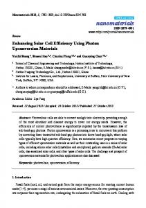
From VLD
Original Decoder
To Display
Quantizer indicator Quantized transform coefficients
Motion Vectors
Our Extension IQ
IDCT
+
Frame Memory
Frame-rate up-conversion
Motion Compensation
Figure 1: The proposed frame-rate up-conversion scheme scheme uses the decoded motion vectors for motion-compensated interpolation.
requires extra motion information to be sent. In [4], the motion-compensated interpolation scheme is performed based on an object-based interpretation of the video. The main advantage of the scheme is that the decoded motion and segmentation information is used without refinement. However, a proprietary codec is used. The method that we propose is applicable to most video coding standards and does not require an extra motion estimation. Our motion-compensated interpolation scheme is based on the decoded motion vectors which are used for inter-coding. Our method does not require any proprietary information to be sent. One of the major advantages of this scheme over other motion-compensated interpolation schemes is that computation is saved on the decoder side. Besides the cost saving on the decoder side, another advantage of this scheme is high quality. Our simulation results show that the proposed scheme performs better than two conventional low-cost up-conversion methods. Our scheme eliminates the motion-jerkiness shown in the frame-repetition scheme and reduces the motionblurriness appeared in the non-motion-compensated linear-interpolation. In addition, our motion estimation scheme is based on a neighborhood-relaxation formulation [3]. Our true motion estimation process provides a more accurate representation of the motion within a scene, and hence it becomes easier to reconstruct information which needs to be recovered before display. Using the neighborhood-relaxation motion estimation algorithm results in better picture quality (0.15dB–0.3dB SNR) than using the conventional full-search motion estimation algorithm.
MOTION COMPENSATED INTERPOLATION The proposed motion-compensated frame-rate up-conversion scheme uses the decoded motion vectors (cf. Figure 1). Here, we discuss the interpolation of frame Ft using information from frames Ft?1 and Ft+1 . It is easy to generalize the method for interpolating frame Ft using information from frames Ft?m and Ft+n . The proposed interpolation scheme is based on the following premise: as shown
In IEEE Workshop on Multimedia Signal Processing, Los Angeles, CA, Dec. 1998.
in Figure 2(a), if block Bi moves ~vi from frame Ft?1 to frame Ft+1 , then it is likely that block Bi moves ~vi =2 from frame Ft?1 to frame Ft , i.e., I (p ~
? ~vi ; t ? 1) = I (p~ ? ~v2i ; t) = I (p~; t + 1) 8p~ 2 Bi
where p~ = [x; y ]t indicates the pixel location, I (p~; t) means the intensity of the pixel [x; y] at time t, and ~vi is the motion vector of block Bi . From the above, the basic technique to interpolate frame Ft based on frame Ft?1 and frame Ft+1 can be stated as follows: I~(p ~
� � ? ~v2i ; t) = 12 I (p~ ? ~vi ; t ? 1) + I (p~; t + 1) 8p~ 2 Bi
(1)
where I~(p~; t) means the reconstructed intensity of the pixel [x; y ] at time t. Because the pixel intensity at frame Ft is reconstructed as the average of the intensity of the corresponding pixels at frame Ft?1 and at frame Ft+1 , this process can be referred to as a motion-compensated linear-interpolation. Thus far, we have discussed how motion-compensated interpolation can be used to assist in the recovery of missing frames. However, in this discussion it has been assumed that a pixel can be seen in all frames, while in reality a pixel may be occluded or uncovered. This is a major source of failure for conventional linear interpolation and is a potentially larger problem for the motion-compensated interpolation. The reason is that the motion in these areas can not be tracked, and hence any motion information provides misleading/incorrect data. Therefore, additional heuristics are needed to interpolate the uncovered and occluded regions: 1. Uncovered region: We identify a block Bi as an uncovered region, when it can be seen in Ft and Ft+1 , but not in Ft?1 . When a block Bi in Ft+1 is coded as an INTRA block, it usually implies there is no matched displacement block in Ft?1 . That is, Bi is in the uncovered region (from Ft?1 to Ft+1 ). Since we have no information about the uncovered region from Ft to Ft+1 , we use a heuristic: a pixel is in the uncovered region if it (1) belongs to the corresponding location of an INTRA block Bi and (2) has not been motion compensated by other blocks. Hence, we have the following formulation: I~(p ~; t)
= I (p~; t + 1) 8p~ 2 Bi
(2)
Note that since the block is INTRA coded, there is no motion information about the block. In this heuristic, we assume that the occluded and uncovered regions are stationary (~v = 0). The reason is that object occlusion and reappearance often happen in the background. And, it is most likely that the background has no motion. Hence, zero motion vectors are used for the occluded and uncovered regions. 2. Occluded region: Similar to the uncovered region, we identify a block Bi as an occluded region, when it can be seen in Ft?1 and Ft but not in Ft+1 . All the blocks that are not in the occluded region can be motion compensated by
In IEEE Workshop on Multimedia Signal Processing, Los Angeles, CA, Dec. 1998.
Eq. (1) and Eq. (2). When I~(p~; t) has not been assigned any value by Eq. (1) and Eq. (2), it usually is in the occluded region. As a result, I~(p ~; t)
= I (p~; t ? 1)
(3)
In summary, our method has discussed how decoded motion vectors can be used to provide a motion-compensated interpolation. With this dependency on the motion estimation algorithm at the encoder, it had been argued that a more accurate estimate of the true motion will yield better reconstruction of interpolated frames. That is, if v~i =2 is an accurate estimate of the true motion, then jjI~(p ~; t) ? I (p ~; t)jj will be small. A suitable candidate for such a motion estimation algorithm would be the true motion estimation algorithm, such as (presented in [2, 3]): motion of Bi
= arg min fDFD(Bi ; ~v) + ~v
X
�i;j
Bj 2N (Bi )
� DFD(Bj ; ~v + ~�)g
(4)
where DFD stands for the displaced frame difference, N (Bi ) means the neighboring blocks of Bi , � is the weighting factor for different neighboring blocks, and a small ~� is incorporated to allow local variations of motion vectors among neighboring blocks due to the non-translational motions. If a motion vector can reduce the DFD of the center block and the DFDs of its neighbors, then it is selected to be the motion vector for the encoder. In other words, when two motion vectors produced similar DFDs, the one that is closer to its neighbors’ motion will be selected. In [3], we show that the neighborhood-relaxation motion tracker captures the true movement of the block more accurately than the widely adopted the minimal DFD criterion: motion vector = arg minfDFD(~v )g
~v
(5)
In terms of coding efficiency, our proposed motion estimation algorithm performs as well as the original minimal-residue motion estimation algorithm [2]. SIMULATION RESULTS To evaluate the performance of the proposed method of frame-rate up-conversion which uses the true motion vectors, a variety of 30 fps test sequences are encoded at 15 fps. The missing frames are interpolated and compared to the original frames. This process is illustrated in Figure 2(b). In Table 1, a summary of the average PSNR over all skipped frames is given. It is evident from this table that for sequences in which there is hardly any motion (e.g., akiyo and container) the linear interpolation does a better job of recovering the missing data. However, for the rest of the test sequences which contain moderate to high motion, the proposed method of frame-rate up-conversion performs much better. Next, we examine the performance of our motion-based frame-rate up-conversion using the neighborhood relaxation true motion tracker (see Eq. (4)) compared with the performance of the motion-based frame-rate up-conversion using the original
In IEEE Workshop on Multimedia Signal Processing, Los Angeles, CA, Dec. 1998.
Frame t-1
t
t+1
Bi
vi/2
Original (30 fps)
vi Uncovered Region
Occluded Region
Coded (15 fps) Decoded & Up-convert (15 fps 30 fps)
(a)
(b)
Figure 2: (a) Motion-compensated interpolation. (b) Our performance comparison scheme in the frame-rate up-conversion using transmitted true motion. We drop one of each two frames in the original sequence, then encode the sequence using standard video codec. While we decode the sequence, we also motion-interpolate the missing frames. We compare the skipped original frame and the interpolated reconstructed frame for the performance measurement. Sequences akiyo coastguard container foreman hall monitor mother daughter news stefan
Nonmotion 43.26 dB 26.39 dB 41.89 dB 26.41 dB 35.69 dB 39.07 dB 33.01 dB 18.76 dB
Motion compensated Old ME Our ME 42.71 dB 42.87 dB 30.47 dB 30.62 dB 40.47 dB 40.77 dB 28.30 dB 28.63 dB 36.02 dB 36.15 dB 39.68 dB 39.93 dB 32.78 dB 33.08 dB 21.06 dB 21.20 dB
SNR Improved 0.16 dB 0.15 dB 0.30 dB 0.33 dB 0.13 dB 0.25 dB 0.30 dB 0.14 dB
Table 1: Comparison of different motion-based frame-rate up-conversion. Our neighborhood relaxation motion tracker performs about 0.15dB–0.3dB SNR better than the minimal-residue motion estimation method.
minimal-residue motion estimation (see Eq. (5)). These simulation results show that our true motion estimation algorithm always performs better than the minimalresidue motion estimation method. The margin of gain is about 0.15dB–0.3dB. To get a better sense of the improvement which is achieved by using the proposed method, Figure 3 provides a visual comparison in the foreman sequence. Obviously, the proposed method is much better than linear interpolation. In fact, there is almost a 3dB difference. For the two methods which are motion-assisted, we observe that when the foreman turns his head, the brightness of his face changes. That is, the assumption of intensity conversation over motion trajectory is not valid in this scene. Under this condition, it is extraordinarily difficult for motion estimation algorithms to track the true motion. Hence, the motion vectors estimated by the minimal-residue criterion have many errors and the interpolated frame is quite disturbing. On the contrary, by using our neighborhood-relaxation motion tracker, which is more reliable, the errors can be significantly reduced. The SNR improvement in this example is 1.5 dB.
In IEEE Workshop on Multimedia Signal Processing, Los Angeles, CA, Dec. 1998.
(a)
(b)
(c)
(d)
(e)
(f)
Figure 3: Simulation results for visual comparison. (a) the 138th frame of the “foreman” sequence. (b) the 139th frame, which is not coded in the bit-stream. (c) the 140th frame. (d) the reconstructed 139th frame (26.86 dB) using non-motion-compensated linear-interpolation of the 138th frame and the 140th frame. (e) the reconstructed 139th frame (28.31 dB) using transmitted motion vectors that are generated from full-search motion estimation. (f) the reconstructed 139th frame (29.81 dB) using transmitted motion vectors that are generated from the proposed true motion estimation.
SUMMARY We have described a novel frame-rate up-conversion algorithm that uses decoded true motion vectors for motion-compensated interpolation, i.e., using the information contained within the bit-stream. Because of no motion estimation again on the decoder side, this technique provides a low-cost solution for playing back highlycompressed video in better picture quality. REFERENCES [1] R. Castagno, P. Haavisto, and G. Ramponi, “A Method for Motion Adaptive Frame Rate Up-conversion,” IEEE Trans. on Circuits and Systems for Video Technology, 1996. [2] Y.-K. Chen and S. Y. Kung, “Rate Optimization by True Motion Estimation,” in Proc. of IEEE Workshop on Multimedia Signal Processing, 1997. [3] Y.-K. Chen, Y.-T. Lin, and S. Y. Kung, “A Feature Tracking Algorithm Using Neighborhood Relaxation with Multi-Candidate Pre-Screening,” in Proc. of ICIP’96. [4] S.-C. Han and J. W. Woods, “Frame-rate Up-conversion Using Transmitted Motion and Segmentation Fields for Very Low Bir-rate Video Coding,” in Proc. of ICIP’97. [5] K. Kawaguchi and S. K. Mitra, “Frame Rate Up-Conversion Considering Multiple Motion,” in Proc. of ICIP’97. [6] R. Thoma and M. Bierling, “Motion Compensating Interpolation Considering Covered and Uncovered Background,” Signal Processing: Image Communications, 1989.